1
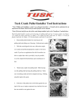
Study Unit
Four-Stroke
Internal-Combustion
Engines
By
Ed Abdo
About the Author
Edward Abdo has been actively involved in the motorcycle and ATV industry for over 25
years. He received factory training from Honda, Kawasaki, Suzuki, and Yamaha training
schools. He has worked as a motorcycle technician, service manager, and Service/Parts
department director.
After being a chief instructor for several years, Ed is now the Curriculum Development
Manager for the Motorcycle Mechanics Institute in Phoenix, Arizona. He is also a contract instructor and administrator for American Honda’s Motorcycle Service Education
Department.
All terms mentioned in this text that are known to be trademarks or service
marks have been appropriately capitalized. Use of a term in this text should
not be regarded as affecting the validity of any trademark or service mark.
Copyright © 1998 by Thomson Education Direct
All rights reserved. No part of the material protected by this copyright may be
reproduced or utilized in any form or by any means, electronic or mechanical,
including photocopying, recording, or by any information storage and retrieval
system, without permission in writing from the copyright owner.
Requests for permission to make copies of any part of the work should be mailed
to Copyright Permissions, Thomson Education Direct, 925 Oak Street, Scranton,
Pennsylvania 18515.
Printed in the United States of America.
Reprinted 2001
iii
Preview
In the previous study unit you learned about the various motorcycle and ATV engine configurations. Now we’ll focus on how motorcycle and ATV engines operate. We’ll begin by discussing
certain physical laws that pertain to engines. Next we’ll describe the theory of operation for a basic internal-combustion engine. After you understand basic engine operation, we’ll focus on the
four-stroke engine. We’ll discuss the basic components used in a four-stroke engine and then take
an in-depth look at how the four-stroke engine operates.
When you complete this study unit, you’ll be able to
· Explain the physical laws associated with motorcycle and ATV engines
· Describe the operation of a basic internal-combustion engine
· Explain how fuel and air are used to make an engine operate
· Identify the component parts used in a four-stroke engine
· Describe the theory of operation for a four-stroke engine
v
Contents
03300400tc.txt
INTRODUCTION . . . . . . . . . . . . . . . . . . . . . . . . . . . . .
Matter
Viscosity
Boyle’s Law
Pressure Differences
Momentum
Laws of Motion
Energy
1
BASIC INTERNAL-COMBUSTION ENGINE OPERATION . . . . . . . . .
5
Types of Combustion Engines
Basic Construction of the Internal-Combustion Engine
Methods of Internal Combustion
Results of Combustion
Internal-Combustion Engine Operation
BASIC FOUR-STROKE ENGINE COMPONENTS. . . . . . . . . . . . . . 11
Four-Stroke Engine Cylinder Heads
Four-Stroke Engine Camshafts
Valve Train
Four-Stroke Engine Cylinders
Crankshafts
Multicylinder Crankshafts
Connecting Rods
Crankcases
FOUR-STROKE ENGINE THEORY OF OPERATION . . . . . . . . . . . . 32
Valve Operation
Carburetor
The Intake Stroke
The Compression Stroke
The Power Stroke
The Exhaust Stroke
ROAD TEST ANSWERS . . . . . . . . . . . . . . . . . . . . . . . . . . 37
EXAMINATION . . . . . . . . . . . . . . . . . . . . . . . . . . . . . 39
1
Four-Stroke Internal-Combustion Engines
INTRODUCTION
As you’ve previously learned, there are two basic types of gasoline
engines used in today’s motorcycles and ATVs: the two-stroke engine
and the four-stroke engine. The engine type is determined by the
number of piston strokes needed to complete one full engine cycle.
One full engine cycle consists of four stages of operation: intake, compression, power, and exhaust. The two-stroke engine takes only two
piston strokes to complete the cycle. The four-stroke engine takes four
piston strokes to complete the cycle. However, both two-stroke and
four-stroke engines are similar in that they both change heat energy
into mechanical energy which is used to power the motorcycle or
ATV.
Before we go into detail on how engines operate, it’s important that
you understand certain terms and principles related to gasoline engines and the combustion process.
Matter
Matter can be described as any substance that occupies space and has
weight. Matter can’t be created or destroyed but can be changed from
one form to another by a chemical or physical process. An example of
matter changing from one form to another is a block of ice. The ice
turns to water if not kept at a freezing temperature. Also, if enough
heat is applied, the water can be changed to steam.
Matter can be in the form of a solid, liquid, or gas. The block of ice in
the previous example is considered to be solid matter because it has
three dimensions (length, width, and depth) that can be measured.
When the ice melts, it changes from a solid form into a liquid form
(water). A liquid has no definite shape and conforms to the shape of
the container holding it. A liquid has the ability to transmit pressure
but can’t be compressed. Another interesting fact about a liquid is
that it won’t burn! The following are two terms describing liquids that
relate to engine operation.
· An atomized liquid consists of liquid drops suspended in air. An
example of an atomized liquid is an early morning fog. Because
an atomized liquid is still a liquid, it won’t burn.
· A vaporized liquid is a liquid that’s converted to a gaseous state
though a heating process. A vaporized liquid has the ability to
burn. Vaporized liquids are used to make an engine run.
2
Four-Stroke Internal-Combustion Engines
Steam is a gas or gaseous matter. Keep in mind that we aren’t talking
about gasoline when we talk about gas. Gasoline is a liquid. A gas has
no definite shape and, like a liquid, conforms to the shape of its container. A gas can transmit pressure but is lighter than a liquid when
compared in equal volumes. Unlike a liquid, a gas is highly compressible.
An excellent example of a gas is the air we breathe. Air is made up of
approximately 78% nitrogen, 21% oxygen, and 1% inert or inactive
gases. The oxygen in the air keeps us alive and also helps an engine
run at its best.
Air density can be described as the amount of oxygen per given volume of space—or in other words, the thickness of air. The air all
around us is actually compressed. At sea level the air pressure is 14.7
pounds per square inch (psi). Air density decreases as we increase altitude or when the temperature rises. When the air density decreases
there are fewer oxygen molecules in the air. It’s more difficult for you
to work at the same level of intensity at 10,000 feet above sea level
than at 1,000 feet above sea level. It’s also more difficult to work at the
same level of intensity on a very hot and humid day than on a cool
and dry day. The same changes affect how an engine runs! As air
density decreases, there are fewer oxygen molecules in the air for you
and your engine to breathe.
Viscosity
A liquid will flow through a path such as a water hose. How fast a
liquid flows is affected by its path of flow. For example, a liquid won’t
flow uphill without some sort of pressure behind it. The temperature
of a liquid also affects its ability to flow. As the temperature of a liquid increases, the liquid has a tendency to get thinner. This change is
known as viscosity. Viscosity is the measure of a liquid’s resistance to
flow. You’ll normally see the word viscosity when referring to oil
used in engines. A viscosity with a high number has a greater resistance to flow as compared to a low viscosity number.
Boyle’s Law
As we stated earlier, a gas, like air, can be compressed. There’s a
physical law known as Boyle’s law which states that “the product of
the pressure and the volume of a given mass of gas is constant if the
temperature isn’t changed.” Boyle’s law tells us that when a gas is
compressed, its temperature and pressure increase. The more a gas is
compressed, the greater its temperature and pressure. Each time you
decrease the volume of a gas by one half, you double the pressure.
Four-Stroke Internal-Combustion Engines
3
Pressure Differences
Pressure differences result in movement of a gas from a high-pressure
area to a low-pressure area, moving any matter that may be in the
way along with it. High pressure always seeks low pressure. A common example of pressure differences can be seen every day in the
weather around us. In engines, carburetion and the intake or induction phase take advantage of pressure differences for operation.
You’ll learn more about this later.
Momentum
Velocity is the speed of an object. Mass is the weight of any form of
matter. Momentum is the driving force that’s the result of motion or
movement. Momentum is determined by multiplying mass (weight)
times velocity. (Momentum = Mass ´ Velocity)
Laws of Motion
Two laws of motion concerned with understanding engine operation
are the law of inertia and the law of action and reaction. The law of inertia states that anything at rest or in motion tends to remain at rest or
in motion until acted upon by an outside force. The law of action and
reaction states that for every action there’s an equal and opposite reaction.
Energy
Energy is the ability to do work. If we have lots of energy, we can do
lots of work. Energy itself can’t be seen; however, the results of energy can be seen. An example is lifting a box and setting it on a table.
Only the physical movement of the box can be seen.
Energy exists in many forms and can be changed from one form to
another. For example, a battery changes chemical energy to electrical
energy. No conversion of energy is 100% efficient. An example is your
home heating system. As your heating system burns fuel, most of the
heat is used to warm your home; however, some of the heat is lost up
the chimney. The same is true in a motorcycle engine. Burning fuel in
the engine provides the energy to move the motorcycle, but some energy is lost in friction and heat produced by the engine.
There are two types of energy:
· Potential energy is stored energy, such as in a charged battery or
a can of gasoline.
4
Four-Stroke Internal-Combustion Engines
· Active energy (or kinetic energy) is energy in use or in motion,
such as when a battery is used to light a lamp or when gasoline
is used to run an engine.
Road Test 1
At the end of each section of Four-Stroke Internal-Combustion Engines, you’ll be asked to
check your understanding of what you’ve just read by completing a “Road Test.” Writing
the answers to these questions will help you review what you’ve learned so far. Please complete Road Test 1 now.
1. If you travel from sea level to 5000 feet above sea level, what happens to the air density?
2. What does “viscosity” measure?
3. Can a liquid be compressed?
4. True or False? Energy can be changed from one form to another.
5. Define the “law of inertia.”
6. What are the two types of energy?
7. If a gas is compressed, what happens to its temperature?
8. What type of liquid has the ability to burn?
Check your answers with those on page 37.
Four-Stroke Internal-Combustion Engines
5
BASIC INTERNAL-COMBUSTION ENGINE OPERATION
Previously we discussed the basic components and operation of an
engine. Now we’ll discuss these topics again but in greater detail.
Motorcycle and ATV engines use a principle called combustion to operate. Combustion is the rapid combining of oxygen molecules with
other elements. Chemical changes can result in the release of heat
when elements are combined with oxygen. Heat usually speeds up
any chemical changes and can act as a catalyst. A catalyst speeds up
the chemical reaction of something without undergoing any change
itself. Cold usually slows down most chemical changes. This is why
engines tend to run better when warmed up than when they’re first
started.
Types of Combustion Engines
The engines found in all modern motorcycles and ATVs are internalcombustion engines. In an internal-combustion engine, compressed
fuel and air is burned inside the engine to produce power. The
internal-combustion engine produces mechanical energy by burning
fuel. In a motorcycle engine, fuel is sent to the engine through an induction system, where it’s burned inside to produce the power that’s
used to help make the engine run. In contrast, an external-combustion
engine burns fuel outside of the engine. A steam engine with a boiler
is an example of an external-combustion engine. We won’t discuss the
external-combustion engine design here because it’s not relevant to
motorcycle use.
Basic Construction of the Internal-Combustion Engine
Let’s begin by reviewing some of the common parts in an engine
(Figure 1). The cylinder is a hollow metal tube. The top end of the
cylinder is sealed by a metal cover that’s called a cylinder head. The
cylinder head is bolted onto the top of the cylinder. The piston is a
can-shaped metal component that can move up and down inside the
cylinder. The piston is the main moving part in an engine.
The area above the piston and below the cylinder head is called the
combustion chamber. In this chamber, a mixture of air and gasoline is
compressed and burned to produce power. A spark plug is screwed
into a threaded hole in the cylinder head. The end of the spark plug
protrudes through the cylinder head and into the combustion chamber. The spark plug is used to ignite the compressed air-and-fuel mixture in the cylinder and cause it to burn. The sparking action of the
spark plug is controlled by the engine’s ignition system, which we’ll
discuss in detail in a later study unit.
6
Four-Stroke Internal-Combustion Engines
FIGURE 1—This drawing
shows a simplified cutaway
view of an engine. During
operation, the piston
moves up and down inside
the cylinder. This movement is transferred to the
crankshaft through the
connecting rod.
When the air-and-fuel mixture burns in the combustion chamber, it
produces a small, contained explosion. The expansion of the gases
due to this explosion is enough to force the piston downward into the
cylinder. The bottom end of the piston is attached to a connecting rod
and crankshaft assembly. When the piston is forced downward in the
cylinder, the piston’s downward motion is transferred to the rod and
crankshaft. The rod and crankshaft then convert the up-and-down (or
reciprocating) motion of the piston into circular or rotary motion.
Four-Stroke Internal-Combustion Engines
7
Now, let’s take a few minutes to review a few terms that were presented earlier. When a piston is at its highest position in the cylinder,
it’s said to be at top dead center (TDC) (Figure 2). When the piston is at
its lowest position in the cylinder, it’s said to be at bottom dead center
(BDC). The total distance that the piston moves from the top of the
cylinder to the bottom of the cylinder is called the stroke.
FIGURE 2—This illustration shows a cutaway view of an actual engine with the piston located at top dead
center (left) and at bottom dead center (right).
The outside surface of a piston has several horizontal grooves cut into
it. Each groove holds a metal ring called a piston ring. A piston ring is
a metal ring that’s split at one point and is designed to be springy.
The piston rings slip over the outside of the piston and fit into the piston ring grooves. Once they’re in place, the rings stick out like ridges
on the surface of the piston. When a piston is inside a cylinder, the
piston rings press outward against the walls of the cylinder. This
helps form a tight seal between the piston and the cylinder, which is
necessary for proper engine operation.
Methods of Internal Combustion
There are two methods of initiating normal combustion in an engine.
The first method is ignition, which is the contact of a fuel with a spark.
The second method is by reducing the space confining oxygen and a
8
Four-Stroke Internal-Combustion Engines
combustible material, which produces heat. Motorcycle and ATV engines use a combination of these two methods. The air-and-fuel mixture is compressed into a very small space. An ignition spark begins
the combustion process. As the air-and-fuel mixture burns, the hot expanding gases push the piston down. The combustion process
changes potential energy in the form of the air-and-gas mixture
(chemical energy) to active (kinetic) energy in the form of heat. There
are three phases of combustion that occur during the power stroke of
the internal-combustion engine.
Combustion Lag
The first phase of the internal-combustion engine process starts after
the piston compresses the air-and-fuel mixture. The spark plug
ignites a small portion of this mixture. A ball of fire spreads outward
and begins to consume the remaining compressed air-and-fuel mixture. However, this ball of fire that initiates combustion doesn’t immediately spread outward. Before the chain reaction spreads to the
outside area of the combustion chamber, a short period of relatively
slow burning takes place. This slow burning is known as combustion lag.
Active Combustion
The second phase of the internal-combustion engine process begins
when the initial combustion lag is overcome and the chain reaction
begins to spread quickly outward. A rapid temperature and pressure
buildup occurs as the charge is consumed. The chain reaction of burning molecules accelerates and the chemical conversion causes heat to
be released very quickly. This increase in temperature causes the
pressure in the cylinder to increase. This phase is known as active combustion.
Post Combustion
As the piston moves down and the volume inside the cylinder increases, the pressure drops and power is absorbed by the piston. The
cylinder now eliminates spent gases to prepare for the next cycle of
fresh air-and-fuel mixture. All engines begin to release exhaust gases
out of the cylinder well before the piston reaches bottom dead center.
This is known as post combustion.
Results of Combustion
The heat and power generated within the combustion chamber produce work which is realized through the crankshaft and eventually
through the drive system of the motorcycle or ATV. Although most
four-stroke engines run at lower temperatures, cylinder head temperatures can be as high as 300–375° Fahrenheit (F). Combustion
Four-Stroke Internal-Combustion Engines
9
chamber gas temperatures within the engine are known to be as high
as 4000° F. This relates to cylinder pressures reaching 800–1000
pounds per square inch (psi). The heat produced expands the gases in
the combustion chamber and pushes the piston towards BDC.
Chemical changes occur during combustion which convert the fueland-air mixture into the following chemicals:
· Carbon monoxide (CO), which results from partially burned
fuel or fuel that’s not completely burned during the combustion
process. As mentioned in a previous study unit, remember that
carbon monoxide is a colorless, odorless, poisonous, and deadly
gas.
· Hydrocarbons (HC), which result from unburned or raw fuel
· Carbon dioxide (CO2), which is the result of complete combustion
· Oxides of nitrogen (NOX), which are forms of oxidized nitrogen
resulting from extremely high combustion temperatures
· Water (H2O), which also results from complete combustion. Believe it or not, for every gallon of fuel burned, approximately
one gallon of water is produced in a vaporized form.
In the United States, the Environmental Protection Agency (EPA) has
developed emission standards for street-legal motorcycles. Since 1978,
motorcycles designed to be ridden on the street must comply with
EPA emission standards. The two key emissions produced by motorcycles and monitored by the EPA are HC and CO. The EPA also
monitors noise emissions.
Internal-Combustion Engine Operation
So far, we’ve looked at the basic internal-combustion process of a
typical engine. Now, let’s take a look at how combustion is used to allow the engine to operate. In order to work, all internal-combustion
engines must do four basic things. An engine must
· Take in air and fuel
· Squeeze or compress the air-and-fuel mixture
· Ignite and burn the mixture
· Get rid of the burned gases
The engine actions we’ve just described are the four stages of engine
operation. The proper names for these stages are intake, compression,
power, and exhaust. When an engine is operating, it continually runs
through these four stages, over and over again.
10
Four-Stroke Internal-Combustion Engines
Intake Stage. Air that has been mixed with fuel is drawn into the cylinder.
Compression Stage. The piston rises and compresses the air-and-fuel
mixture trapped inside the combustion chamber.
Power Stage. The air-and-fuel mixture is ignited. The contained explosion of the fuel pushes the piston back down the cylinder. The
downward motion of the piston is transferred through the connecting
rod to the crankshaft.
Exhaust Stage. The exhaust gases are released from the cylinder. The
four stages then begin all over again.
One engine cycle is a complete run through all four stages of operation:
intake, compression, power, and exhaust. Keep in mind that the four
stages of operation we’ve described occur very quickly, and they repeat continually for as long as the engine is running. All motorcycle
and ATV engines operate in these same four basic stages, and all the
stages must occur in order for the engine to run properly. To understand how an engine works, one of the most important things you can
do is memorize the four stages of engine operation. Once you understand these four stages, everything else we discuss about engine operation will fall into place.
Road Test 2
1. What are the four stages of engine operation?
a. Stage #1 __________________________
b. Stage #2 __________________________
c. Stage #3 __________________________
d. Stage #4 __________________________
2. Explain what occurs during each of the four stages of engine operation.
a. Stage #1 _________________________________________________
b. Stage #2 _________________________________________________
c. Stage #3 _________________________________________________
d. Stage #4 _________________________________________________
3. What type of combustion engine is found on all modern-day motorcycles and ATVs?
4. The piston moves up and down in the _______.
5. _______ are used to form a tight seal between the piston and the cylinder.
(Continued)
Four-Stroke Internal-Combustion Engines
11
Road Test 2
6. The _______ ignites the air-and-fuel mixture in the combustion chamber.
7. _______ is a deadly gas that results from fuel that wasn’t completely burned during combustion.
8. What term is used to describe the location of the piston when it’s at the highest point, closest to the spark plug?
Check your answers with those on page 37.
BASIC FOUR-STROKE ENGINE COMPONENTS
Now that we’ve reviewed the important basics of engine operation,
let’s look at the four-stroke motorcycle and ATV engine components
in more detail. We’ll cover all the basic parts of an engine and explain
how they’re used. Many of these basic parts are found in both fourstroke engines and two-stroke engines. Refer to the illustrations for
reference as we discuss each component. Be aware that not all engines
look exactly alike. However, the illustrations provided are typical of
many motorcycle and ATV four-stroke engines you’ll see.
Four-Stroke Engine Cylinder Heads
Cylinder heads are constructed of aluminum alloy or cast iron (Figure 3).
The four-stroke cylinder head holds the intake and exhaust valve
train components and the spark plug. The cylinder head also seals the
top end of the cylinder for compression of the air-and-gas fuel mixture under the spark plug to increase combustion efficiency. Holes in
the cylinder head that are called ports provide for the air-and-fuel intake and exhaust. Cylinder heads also aid in the transfer of heat from
the engine by the use of fins on air-cooled engines or by using water
jackets on liquid-cooled engines.
Many modern four-stroke motorcycles and ATVs use multivalve cylinder heads. Cylinder heads may have anywhere from two valves to
eight valves per cylinder. The intake valve area is usually larger than
the exhaust valve area on the four-stroke engine.
12
Four-Stroke Internal-Combustion Engines
FIGURE 3—This illustration
shows a typical
water-cooled engine
cylinder head attached to
the cylinder. (Copyright by
American Honda Motor Co., Inc. and
reprinted with permission)
Poppet Valves
Four-stroke engines use mechanical valves called poppet valves to control the gases coming into and going out of the engine. Poppet valves,
which are tulip-shaped, open and close every other crankshaft revolution. The poppet valve may be made from stainless steel, carbon steel,
or titanium. The various parts of the valve are shown in Figure 4.
FIGURE 4—The Parts of a
Valve
Four-Stroke Internal-Combustion Engines
13
· The valve tip is the part of the valve that rides against the valveopening device. Most valve tips are stellite-plated for wear. Stellite is an extremely hard metal alloy that resists wear and won’t
soften at high temperatures.
· The keeper groove is where keepers lock the valve and spring retainer in place.
· The valve stem is the thrust surface for the valve guide and is
considered to be a major wear area. If the stem is worn, excessive amounts of oil can pass between the stem and guide into
the combustion chamber. If oil leaks into the combustion chamber, smoke appears in the exhaust.
· The valve neck is the sloped area of the valve that connects the
valve stem to the valve head.
· The valve face mates with the cylinder head valve seat to seal
gases in the combustion chamber and aid in heat transfer. The
valve face is often coated with stellite to reduce wear and prolong the life of the valve.
· The margin supports the valve face and shields the face from
high combustion temperatures.
· The valve head is the bottom portion of the valve and forms a
part of the combustion chamber.
The common wear areas of the valve are the tip, face, stem, and
keeper groove.
Valve Seats
Cylinder head valve seats (Figure 5) are stationary in the cylinder head
and are the sealing surface for the valve face. There are normally at
least three angles cut into the valve seat to allow for better air-andfuel flow into the cylinder through the valve opening.
Valve Guides
Valve guides (Figure 5) are installed in the four-stroke cylinder head.
Valve guides provide a bushing surface for the valve stem.
Valve Stem Seals
Valve stem seals (Figure 6) are installed on the valve guides and are
used to prevent excessive oil from entering between the inside of the
valve guide and valve stem.
14
Four-Stroke Internal-Combustion Engines
FIGURE 5—Valve seats
and guides are located
in the cylinder head. (Copy-
right by American Honda Motor Co.,
Inc. and reprinted with permission)
Valve-Closing Devices
Valve-closing devices keep the valve closed when required. The most
common method to close a valve is with the use of coil springs
(Figure 6) attached between the valve and the cylinder head. The
springs are held in place with valve spring retainers and valve keepers
that fit into the valve keeper grooves. There are usually two coil springs
per valve to reduce the chance of valve float. Valve float is the point at
FIGURE 6—This illustration
shows the valve stem and
components used to close
the valve.
Four-Stroke Internal-Combustion Engines
15
which the valve doesn’t stay in constant contact with the valve train.
Valve float can occur when the valve springs are weak or during excessively high engine speed. Other devices have been used in the
past, such as torsion bars and hairpin springs, but aren’t seen in today’s modern motorcycle or ATV engines.
Valve-Opening Devices
The main valve-opening device is the cam follower. The cam follower
contacts the valve tip and is used to transfer motion from the cam
shaft to the valve. There are two types of valve-opening devices used
on the four-stroke motorcycle and ATV.
One type of valve-opening device is a rocker arm. The rocker arm is a
lever that can gain a mechanical advantage and change the direction
of force applied to it (Figure 7). The rocker arm can also open more
than one valve. There are various rocker arm designs used on the
four-stroke engine but they all perform the same function. A disadvantage of rocker arms is that they create side loads on valve stems
and guides which can cause excessive wear.
FIGURE 7—This illustration
shows a simple diagram of
a rocker arm.
The second type of valve-opening device is the shim and bucket. The
bucket is located above the valve in the cylinder head. The shim may
be located either above or below the bucket. This type of valveopening device doesn’t create side loads and allows for a lighter mass
in the valve train because it has fewer moving parts.
16
Four-Stroke Internal-Combustion Engines
Valve clearance or lash (Figure 8) is necessary to allow for heat expansion, oil clearance, and for proper sealing of the valve. Too little clearance causes improper sealing of the valve and excessive heat. Too
much clearance causes excessive wear and noise.
FIGURE 8—This illustration
shows valve clearance
with a screw and lock nut
for adjustment. Valve
clearance is important to
allow for heat expansion,
oil clearance, and proper
sealing of the valve. (Copyright
by American Honda Motor Co., Inc.
and reprinted with permission)
There are different types of valve lash adjusters used to adjust valves
on motorcycles and ATVs. Three of the most popular types are as follows:
· The screw and lock nut (Figure 8) uses a screw that can be turned
in or out to change the clearance. After the adjustment has been
made, a lock nut holds the screw in place. The screw and lock
nut may be located on the rocker arm, on a push rod, or on a
valve lifter.
· The shim and bucket is used for both a valve-opening device and
an adjustment device. The shims are used to adjust the valves
for proper clearances. Clearances are changed by changing the
size of the shim. The two popular types of shim-and-bucket adjusters are shim-over-bucket, where the shim rests on top of the
bucket and shim-under-bucket, where the shim rests under the
bucket (Figure 9). You must remove the camshaft to replace a
shim with this design.
· Hydraulic valve lash adjusters (Figure 10) automatically adjust for
the proper clearance by using oil pressure to maintain zero lash
at all engine temperatures and speeds.
Four-Stroke Internal-Combustion Engines
FIGURE 9—This illustration
shows the location of the
shims in the shim-overbucket design and the
shim-under-bucket
design valve
adjustments. (Copyright by
American Honda Motor Co., Inc. and
reprinted with permission)
FIGURE 10—This
illustration shows a
hydraulic adjuster valve
which automatically
adjusts for proper valve
clearance. (Courtesy of Ameri-
can Suzuki Motor Corporation)
17
18
Four-Stroke Internal-Combustion Engines
Four-Stroke Engine Camshafts
The purpose of the camshaft (also known as the cam) is to change rotary motion to reciprocating motion. The camshaft is also a mechanical valve timer that controls
· When to open
· How fast to open
· How far to open
· How long to stay open
· When to close
· How fast to close
· How long to stay closed
There are various parts of a camshaft that are important to its ability
to function properly in the four-stroke motorcycle and ATV engine
(Figure 11).
FIGURE 11—The Parts of a
Camshaft
· The base circle is the area of the camshaft that forms a constant
radius from the centerline of the journal to the heel. The heel is
the part of the cam that allows the valve to seat onto the cylinder
head and seal off the combustion chamber.
· Clearance ramps take up the valve clearance and open and close
the valve. These ramps act similarly to a shock absorber and are
used to gently (relatively speaking) open and close the valve.
· The flanks of the cam determine and control the acceleration of
the opening and closing of the valve.
Four-Stroke Internal-Combustion Engines
19
· The nose is the area of the camshaft where the valve is opened
the greatest distance from the cylinder head area; it controls lift
dwell. Lift dwell is the amount of time in crankshaft degrees that
the valve stays open at maximum lift.
· Camshaft lift is a measure of the difference between the base circle and the nose. Depending on the type of engine, this may or
may not translate into the actual valve lift, which is the distance
that the valve actually moves away from the cylinder head.
· The duration of a camshaft is a measure of how long the valve is
held open. Duration is measured in crankshaft degrees.
Most camshafts have what’s known as valve overlap built into them.
Valve overlap occurs between the exhaust and intake strokes. Valve
overlap is the time that both valves are open simultaneously and is
measured in crankshaft degrees. High-performance engines generally
have more valve overlap to allow for more air-and-fuel mixture to be
packed into the cylinder combustion chamber. While this allows for
higher peak power, an engine with a camshaft exceeding 30 degrees
of valve overlap will lack efficiency in the low- and mid-range power
areas of the engine.
Camshaft Drives
The camshaft rotates at one-half the speed of the crankshaft to properly time the intake and exhaust valves with the piston as it moves up
and down the cylinder. There are three methods used to drive a camshaft on a four-stroke motorcycle or ATV engine.
· The chain type of camshaft drive normally operates in an oil bath
to maintain lubrication (Figure 12).
· The gear type of camshaft drive also operates in an oil bath for
lubrication and to reduce noise (Figure 13).
· The toothed-belt type of camshaft drive runs on pulleys with
teeth. This system is very quiet and requires no lubrication;
however, proper alignment and tension are critical (Figure 14).
Camshaft Drive Tensioners
The purpose of a camshaft drive tensioner is to keep the proper tension
on the cam chain or cam belt (Figures 12 and 14). There are manual
tensioners that require adjustment and automatic tensioners which
automatically adjust the tension while the engine is running.
20
Four-Stroke Internal-Combustion Engines
FIGURE 12—Example of a
Chain-Driven Camshaft
(Copyright by American Honda Motor
Co., Inc. and reprinted with permission)
Valve Train
The valve train consists of the valve components in the cylinder head
and the valve drive components previously discussed. These components are used to provide the different types of valve trains found on
four-stroke motorcycle and ATV engines.
· A pushrod with rocker arm is shown in Figure 15A.
· A single overhead cam with rocker arms is shown in Figure 15B.
· A dual overhead cam with rocker arms is shown in Figure 15C.
· A dual overhead cam with shim and buckets is shown in
Figure 15D.
Four-Stroke Internal-Combustion Engines
FIGURE 13—Example of a
Gear-Driven Camshaft (Copyright by American Honda Motor Co.,
Inc. and reprinted with permission)
FIGURE 14—Example of a
Belt-Driven Camshaft (Copyright by American Honda Motor Co.,
Inc. and reprinted with permission)
21
22
Four-Stroke Internal-Combustion Engines
FIGURE 15—Types of Valve Trains (Courtesy of American Suzuki Motor Corporation)
Four-Stroke Engine Cylinders
The purpose of the four-stroke engine cylinder is to guide the piston
as it travels up and down. The cylinder helps to transfer engine heat
and may be either air cooled or liquid cooled (Figure 16).
There are different types of materials used in the construction of a cylinder. Each material has its advantages and disadvantages.
Four-Stroke Internal-Combustion Engines
23
FIGURE 16—This is a typical
liquid-cooled cylinder. A
liquid-cooled cylinder uses
water jackets as opposed
to the cylinder fins used on
an air-cooled cylinder.
· Cast-iron cylinders have a one-piece design and can be fit with
oversize pistons by boring to a larger size. When a cylinder is
bored, material is removed from the cylinder to enlarge the hole.
A larger “oversized” piston is then used in place of the previous
piston. The cast-iron cylinder is inexpensive to manufacture but
has poor heat transfer characteristics when compared to other
materials used to construct cylinders. Cast-iron cylinders are
also very heavy.
· Aluminum cylinders with cast-iron or steel sleeves have much
better heat transfer abilities than cast-iron cylinders and are
much lighter in weight. These cylinders can also be bored to a
larger diameter. In most cases, the sleeve can be replaced if
needed.
· Plated-aluminum cylinders, which are also called Nikasil or composite cylinders, have the best heat transfer characteristics of any
cylinder produced today. They’re the lightest-weight cylinders
available and when properly maintained are the longest-lasting
cylinders. The disadvantage of plated-aluminum cylinders is
that they can’t be bored to a larger diameter and therefore must
be replaced when damaged. These cylinders are expensive to replace when compared to the other types of cylinders.
Cylinders have tiny scratches purposely installed into the cylinder
wall called crosshatching. This crosshatching is created by honing the
cylinder wall with a cylinder hone. The purpose of honing is to help
24
Four-Stroke Internal-Combustion Engines
seat the piston rings and retain a very thin layer of oil on the cylinder
walls to keep them properly lubricated.
Cylinders must be round from top to bottom to work properly. They
shouldn’t have any taper or out-of-roundness. We’ll discuss how to
measure cylinders in a future study unit.
Pistons
The purpose of the piston is to transfer power produced in the combustion chamber to the connecting rod. The piston is manufactured in
a way that makes it directional. This makes it necessary to install the
piston in the specific manner indicated in the service manual.
Pistons are tapered from top to bottom. The top of the piston is
smaller than the bottom to allow for different heat expansion rates of
the piston. To allow for further heat expansion, pistons are cam ground
so they’re oval in shape when cold. When the piston reaches operating temperature, it becomes round to match the cylinder.
There are two common piston-manufacturing methods: cast aluminum and forged. Cast-aluminum pistons are the more common. Forged
pistons use aluminum alloy forced into a die under extreme pressures.
This manufacturing method produces a stronger piston, but makes
the piston more expensive.
A piston has several parts (Figure 17).
FIGURE 17—The Parts of a
Typical Four-Stroke Piston
Four-Stroke Internal-Combustion Engines
25
· The crown is the top of the piston and acts as the bottom of the
combustion chamber. The crown is the hottest part of the piston,
due to combustion chamber temperatures. The crown area expands more than the rest of the piston because it’s hotter and
has more mass. The piston crown may have a positive dome, flat
top, or negative dome. There also may be notches in the crown
to allow for valve relief.
· The ring grooves allow for installation of piston rings. The bottom ring groove of the four-stroke piston has holes or slots for
oil return that help remove oil from the cylinder wall. This also
helps to lubricate the wrist pin. The piston ring lands support the
piston rings.
· The wrist pin boss is where the piston attaches to the small end of
the connecting rod. A hardened tool-steel wrist pin attaches the
piston to the rod. The wrist pin is normally held in place with
retaining clips to prevent it from contacting the cylinder wall.
· The piston skirt is the load-bearing surface of the piston. The piston skirt contacts the cylinder wall and is the primary wiping
surface for the cylinder wall. The largest diameter of the piston
is usually at or close to the bottom of the skirt and 90 degrees
from the wrist pin. This is where the piston is normally measured.
Piston Rings
The purpose of piston rings is to aid in heat transfer from the piston to
the cylinder wall, seal in the combustion gases, and prevent excessive
oil consumption. There are three types of piston rings used on the
four-stroke piston (Figure 18).
· The compression ring is closest to the piston crown and is used to
seal most of the combustion chamber gases. The compression
ring is usually made of cast iron and may be chrome plated, teflon, or moly coated.
· The scraper ring is the middle ring and aids in sealing the combustion chamber gases. The scraper ring scrapes excessive oil
from the cylinder wall. Like the compression ring, the scraper
ring is made of cast iron, but in most cases has no coating.
· The oil control ring is the ring closest to the piston skirt. The oil
control ring removes the oil from the cylinder walls left behind
by the piston skirt.
Piston rings have an end gap to allow for heat expansion. The end gap
is measured by using a feeler gauge after fitting the ring squarely in
the cylinder (Figure 19).
26
Four-Stroke Internal-Combustion Engines
FIGURE 18—Types of Piston
Rings on Four-Stroke
Engine Pistons (Courtesy of American Suzuki Motor Corporation)
FIGURE 19—The piston
ring end gap is measured
using a feeler gauge. (Copyright by American Honda Motor Co.,
Inc. and reprinted with permission)
Crankshafts
As we discussed earlier, the purpose of a crankshaft is to change the
reciprocating motion from the piston into a rotary motion. The main
parts of a crankshaft include journals and counterweights (Figure 20).
Journals give bearing support. Main journals support the mass of the
crankshaft and are located at the center of the rotating axis.
Four-Stroke Internal-Combustion Engines
27
FIGURE 20—One-Piece
Crankshaft Used on
Four-Stroke Engine (Copyright
by American Honda Motor Co., Inc.
and reprinted with permission)
Connecting-rod journals support the connecting rods and are offset
from the main journals.
Counterweights add momentum to the crankshaft. The counterweights
assist in keeping the crankshaft rotating and the engine running
smoothly by counterbalancing the reciprocating masses from the piston and connecting rod. Some engines use remote counterweights,
which are located on a separate shaft and are chain or gear driven.
Remote counterweights must be timed properly with the crankshaft.
There are two different types of crankshafts used in four-stroke engines.
· The one-piece crankshaft is cast or forged as one part (Figure 20).
The one-piece crankshaft is the stronger in design but must be
used with a multipiece connecting rod. Most one-piece crankshafts are cross-drilled for oil delivery to the connecting rod
journals and use plain bearings at the main and connecting-rod
journals. Most one-piece crankshafts use high oil volume and
pressure to the bearings. Generally, you can’t rebuild these
crankshafts.
· The multipiece crankshaft uses crankshaft halves which are cast or
forged (Figure 21). The connecting-rod journal is a pin (crankpin) that’s pressfit into the halves. A one-piece connecting rod
uses a roller bearing at the connecting-rod journal. The multipiece crankshaft generally uses ball bearings on the main journals. Most multipiece crankshafts can be rebuilt. Figure 22
shows an assembled multipiece four-stroke engine crankshaft
with connecting rod.
28
FIGURE 21—Multipiece
Crankshaft Used on
Four-Stroke Engine
FIGURE 22—An Assembled
Multipiece Four-Stroke
Engine Crankshaft
Four-Stroke Internal-Combustion Engines
Four-Stroke Internal-Combustion Engines
29
Multicylinder Crankshafts
Multicylinder crankshafts use different offset positions for each cylinder, depending on the design (Figure 23).
· In the 360° design, both pistons move up and down together.
This design requires more counterweight and tends to vibrate at
higher engine speeds.
· In the 180° design, the pistons move in opposite directions. This
design requires less counterweight and has less vibration at
higher engine speeds. When this design is used on an in-line
four-cylinder engine, a pair of 180° crankshafts are used.
· In the 120° design, the pistons move 120° apart from each other.
This design is used on three- and six-cylinder engines. Sixcylinder engines use a pair of 120° crankshafts.
FIGURE 23—Multicylinder Crankshaft Designs (Courtesy of American Suzuki Motor Corporation)
Connecting Rods
The connecting rod is a lever that transfers power from the piston to
the crankshaft. Connecting rods are usually made of forged steel, titanium, or aluminum and use an I-beam construction. There are two
types of connecting rods used on four-stroke motorcycle and ATV engines.
· The one-piece connecting rod (Figure 24A) is the stronger in design. It uses a roller bearing at the larger end and must be used
with a multipiece crankshaft. The one-piece connecting rod normally has holes or slots on both ends for added lubrication.
· The multipiece connecting rod (Figure 24B) is somewhat weaker in
design when compared to the one-piece rod. The parts of the
30
Four-Stroke Internal-Combustion Engines
multipiece connecting rod consist of the connecting rod,
connecting-rod end cap, and connecting-rod bolts and nuts. The
multipiece connecting rod uses a two-piece plain bearing at the
larger end which normally requires high oil pressure for proper
lubrication. The multipiece connecting rod is normally used
with a one-piece crankshaft.
FIGURE 24—This illustration shows the two types of connecting rods. Figure 24A shows a one-piece
connecting rod with the piston attached. Figure 24B shows a multipiece connecting rod with the piston
detached.
Crankcases
The purpose of the crankcase is to contain and support the major engine components. These components can include the crankshaft, oil
pump, cylinder, primary shaft, primary drive, transmission, and camshaft. The four-stroke crankcase must be vented to the atmosphere to
prevent excessive pressure from building up inside the engine. Today, government regulations require that crankcase ventilation recirculate back through the combustion chamber.
There are three types of crankcases on four-stroke engines.
· One-piece crankcases consist of a case that’s a single-piece construction with a separate access cover to remove parts.
· Vertically split crankcases consist of two case halves that separate
vertically (Figure 25). This design requires the removal of the
cylinders before the case halves can be split.
· Horizontally split crankcases consist of two case halves that separate horizontally. This design allows the bottom halves to be removed with the cylinder(s) still attached to the top half.
Four-Stroke Internal-Combustion Engines
31
FIGURE 25—This engine has
a vertically split crankcase
design. The cylinder and
cylinder head assemblies
must be removed to split
the crankcase halves.
Road Test 3
1. Piston ring end gap is measured using a _______.
2. The _______ attaches the piston to the connecting rod.
3. What type of valve lash adjuster automatically adjusts for proper clearances?
4. What are the three types of camshaft drives found on four-stroke motorcycle and ATV
engines?
5. What’s the purpose of honing a cylinder?
(Continued)
32
Four-Stroke Internal-Combustion Engines
Road Test 3
6. The _______ ring is located closest to the piston crown.
7. What type of cylinder can’t be bored to a larger diameter?
8. The camshaft in a four-stroke engine rotates at _______ the speed of the crankshaft.
9. What’s valve overlap?
10. What crankcase design allows the bottom half to be removed and the cylinders to remain
attached?
11. What part of the valve is considered a major wear area and if worn will allow excessive oil
to pass into the combustion chamber?
12. True or False? The one-piece connecting rod is used with a multipiece crankshaft.
Check your answers with those on page 37.
FOUR-STROKE ENGINE THEORY OF OPERATION
Although the four-stroke engine is somewhat complex in design due
to the parts necessary for it to function, it’s relatively simple in terms
of operation. The engine runs by repeatedly completing a cycle of operation. Each cycle of operation consists of two crankshaft revolutions
in which four piston strokes occur. Each of the four piston strokes
performs a distinct operation. The four operations (or stages) that are
required for the engine to produce power are: intake, compression,
power, and exhaust. These operations must occur in the proper order
for the engine to run correctly.
Valve Operation
As we mentioned earlier, the four-stroke engine uses mechanical
valves: the intake valve and the exhaust valve (Figure 26). These
valves move up and down to open and close during engine operation.
The intake valve opens to allow the air-and-fuel mixture to flow into
the combustion chamber. The exhaust valve opens to allow exhaust
Four-Stroke Internal-Combustion Engines
33
gases to flow out of the combustion chamber after the air-and-fuel
mixture is burned.
The intake and exhaust valves are mechanically lifted to make them
open and close. The valves are lifted by a valve-lifting device that
rests on the lobes of the camshaft. As the camshaft turns, the lobes
open the valves in a timed sequence to match up properly with the
up-and-down motion of the piston. The valve springs hold the valves
closed when they aren’t being forced open by the camshaft and lifting
device.
FIGURE 26—This illustration
shows the intake and
exhaust valves. These
mechanical valves open
and close to allow the
air-and-fuel mixture into
the engine, and the
exhaust gases to leave
the engine. The camshaft
rotates with the crankshaft
to push the valves open
and allow them to close
at the proper times. (Copyright
by American Honda Motor Co., Inc.
and reprinted with permission)
Carburetor
In order to burn properly in an engine, fuel must be mixed with air.
The component that mixes the fuel and air is called a carburetor. Fuel
moves from the fuel tank into the carburetor, where it’s atomized and
mixed with air. The air-and-fuel mixture is then transferred out of the
carburetor and into the cylinder through the intake valve, where it’s
vaporized. We’ll discuss the specific functions and details of the carburetor in a future study unit.
Now, let’s take a closer look at the individual operations, known as
strokes, that occur in the four-stroke engine (Figure 27).
34
Four-Stroke Internal-Combustion Engines
FIGURE 27—This illustration shows the four piston strokes in the sequence needed to complete one cycle
of operation. An engine runs by repeatedly completing this cycle. (Courtesy Kawasaki Motor Corp., U.S.A.)
The Intake Stroke
On the intake stroke, the air-and-fuel mixture enters the cylinder. The
intake sequence starts when the intake valve begins to open. As the
piston moves downward in the cylinder away from the cylinder head,
the volume of the cylinder above the piston expands. This increase in
volume creates a low-pressure area which develops less-thanatmospheric pressure inside the cylinder. With the intake valve open,
a path is completed through the intake manifold and carburetor. In an
effort to balance the pressure difference between the atmospheric
pressure of the outside air and the less-than-atmospheric pressure inside the cylinder, the outside air moves through the carburetor towards the cylinder. (Remember, a high-pressure area will always seek
a low-pressure area.) The intake valve closes and seals the combustion chamber when the piston is near the bottom of its stroke near the
crankshaft.
Four-Stroke Internal-Combustion Engines
35
The Compression Stroke
When the piston approaches bottom dead center, both valves are
closed. The air-and-fuel mixture is now trapped inside the sealed
combustion chamber. At this point the piston begins to rise, which
compresses the air-and-fuel mixture very tightly in the combustion
chamber. This is known as the compression stroke.
The Power Stroke
Just before the piston reaches TDC during the compression stroke, the
engine’s ignition system fires the spark plug. That is, the ignition system produces an electric current that causes a spark to jump across
the two electrodes of the spark plug. When the spark is applied to the
compressed air-and-fuel mixture, a contained explosion occurs and
the compressed air-and-fuel mixture is burned.
When gases explode, they expand rapidly. The force of this contained
explosion pushes the piston down in the cylinder. The connecting
rod, which is connected between the piston and crankshaft, causes the
downward motion of the piston to force the crankshaft to rotate. This
is known as the power stroke.
The Exhaust Stroke
As the piston moves downward during the power stroke, the exhaust
valve opens. By the time the piston reaches bottom dead center, the
exhaust valve is completely open. As the piston moves up again, it
pushes the burned gases out the exhaust valve. This is known as the
exhaust stroke.
Once the exhaust stage is completed, the four stages of operation begin again. The movement of the camshaft closes the exhaust valve
and opens the intake valve, and the piston moves down to begin a
new intake stage.
The four stages of operation continue as long as the engine is operating. Keep in mind that these cycles are repeated at a very high rate of
speed. An average motorcycle engine crankshaft rotates anywhere
from 1000 to 10,000 revolutions every minute. This means that these
engine cycles are repeated thousands of times in a single minute.
36
Four-Stroke Internal-Combustion Engines
Road Test 4
1. If the piston is rising towards TDC and both valves are closed, the engine is on the _______
stroke.
2. During the _______ stroke, the piston is moving down in the cylinder and the intake valve
is open.
3. Hot gases are released from the engine during the _______ stroke.
4. During the _______ stroke, the air-and-fuel mixture is ignited and the explosion pushes
the piston down in the cylinder.
5. The typical four-stroke engine contains mechanical valves called the ______ valve and the
_______ valve.
6. In a four-stroke engine, the item that mixes the air and fuel together is called the _______.
Check your answers with those on page 37.
37
Road Test Answers
1
3
1.
The air density will be reduced.
1.
feeler gauge
2.
A liquid’s resistance to flow
2.
wrist pin
3.
No
3.
Hydraulic
4.
True
4.
Chain, belt, and gear
5.
Anything at rest tends to remain at
rest, and anything in motion tends to
remain in motion, until acted upon by
an outside force.
5.
Honing helps to seat piston rings and
retains oil on the cylinder wall for lubrication.
6.
Active (or kinetic) energy and potential energy
6.
compression
7.
Plated aluminum
7.
The temperature increases.
8.
one-half
8.
Vaporized liquid
9.
The time that both the intake and exhaust valves are open simultaneously
2
1.
2.
a.
b.
c.
d.
Intake
Compression
Power
Exhaust
10.
Horizontally split
11.
Valve stem
12.
True
4
Air and fuel is drawn into the cylinder. The mixture is compressed. The
mixture is ignited and burns. The
gases are released.
1.
compression
2.
intake
3.
Internal-combustion engines
3.
exhaust
4.
cylinder
4.
power
5.
Piston rings
5.
intake, exhaust
6.
spark plug
6.
carburetor
7.
Carbon monoxide (CO)
8.
Top dead center (TDC)
Examination
ONLINE EXAMINATION
For the online exam, you must use this
EXAMINATION NUMBER:
03300400
When you’re confident that you’ve mastered the material in your studies, you can
complete your examination online. Follow these instructions:
1.
2.
3.
4.
Write down the eight-digit examination number shown in the box above.
Click the Back button on your browser.
Click the Take an Exam button near the top of the screen.
Type in the eight-digit examination number.