1
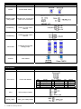
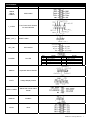
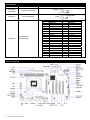
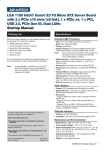
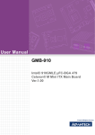
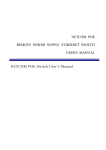
SIMB-A21
Intel® H61 LGA1155 socket for Intel® Sandy Bridge
ATX Motherboard Startup Manual
Packing List
Before you begin installing your card, please make sure that
the following items have been shipped:
• 1 x SIMB-A21 ATX Motherboard
• 1 x CD ROM per carton, which contains Drivers
• 1 x SATA cable kit (SATA/Power)
• 1 x I/O Shield
• 1 x Startup Manual per carton
If any of these items are missing or damaged, please contact
your distributor or sales representative immediately.
Note1:
Acrobat Reader is required to view any PDF file. Acrobat
Reader can be downloaded at: www. adobe.com/Prodindex/
acrobat/readstep.html (Acrobat is a trademark of Adobe).
Disclaimer and Notice
The manufacturer reserves the right to make changes, without notice, to any product, including circuits and/or software
described or contained in this manual in order to improve
design and/or performance. The manufacturer assumes
no responsibility or liability for the use of the described
product(s), conveys no license or title under any patent,
copyright, or masks work rights to these products, and
makes no representations or warranties that these products
are free from patent, copyright, or mask work right infringement, unless otherwise specified. For the detail product
information, please refer to user’s manual.
Specifications
System
• CPU: LGA1155 socket for Intel Sandy Bridge Processor,
Intel Core i7-2600 3.4GHz, Intel Core i5-2400 3.1GHz,
Intel Core i3-2120 3.3GHz,Pentium G850 2.9GHz,
Celeron G540 2.5GHz
• FSB: 1333 / 1066 MHz
• BIOS: AMI 32 Mb SPI BIOS
• System Chipset: Intel H61
• I/O Chipset: Nuvoton NCT6776F
• Memory: Two 240-pin DIMM sockets support up to 8 GB
Dual Channel DDR3 1333/ 1066 SDRAM
* Base on OS limitation, when using the memory over 4GB
capacity under 32-bit OS, system will only recognize less
than 3GB. And 64-bit OS will don't have this limitation.
• Watchdog Timer: Reset: 1sec.~255 min. and 1sec. or 1
min./step
• H/W Status Moniton: Monitoring temperatures, voltages,
and cooling fan status. Auto throttling control when CPU
overheat
• Expansion Slots: 1 x PCI Express x16, 1 x PCI Express
x1, 4 x PCI (PCI Rev. 2.3 compliant)
• DIO: 8 bit
• S3 / S4: Yes
• TPM: 2x10 Pin header
• Wake up on LAN or Ring: LAN (PME / RPL)
• Smart Fan Control: Yes
Safety Declaration
Display
This device complies with the requirements in Part 15 of
the FCC rules. Operation is subject to the following two
conditions:
1. This device may not cause harmful interference.
2. This device must accept any interference received,
including interference that may cause undesired
operation.
•Chipset: Integrated HD Graphics 2000↑
• • Max. Resolution: 2048 x 1536 bpp(@ 75Hz)
• VGA: Yes , Integrated Graphics
• LVDS / DVI / HDMI: Through ADD2 LVDS Card
• Secondary VGA: Yes , through ADD2 card
Audio
For more information on this and other Advantech
products, please visit our website at:
http://www.advantech.com
http://www.advantech.com/eplatform
For technical support and service, please visit our
support website at:
http://www.advantech.com/support
This manual is for the SIMB-A21 series Rev. A1.
Part No. 20060A2110
Printed in China
1st Edition
May 2012
•Audio Codec: Realtek, ALC892, 5.1 HD Audio
• Audio Interface: Mic in, Line in, Line out
Ethernet
•LAN1: RTL8111E Gigabit LAN
•LAN2: RTL8111E Gigabit LAN
SIMB-A21 Startup Manual 1
Jumpers
Label
Function
PSCN1
AT/ATX Mode setting
Note
KBUSB_PWR1
USB_PWR1
K/B,M/S +5V/ +5Vsb select
USB +5V/ +5Vsb select
JCOMPWR_1
COM1 for Power select
5V&12V
JCOMPWR_2
COM2 for Power select
5V&12V
JSETCOM2
COM2 RS-232/422/485
Setting jumper
JCMOS1
Clear CMOS
Connectors Label
Function
JFP1+JFP2
Front Panel Header
JFP3
KEYLOCK pin Header
Note
Pin
12
9
6
3
Signal
SYS RST_GND
SYS_RST#
PWRBTN_GND
PWRBTN_IN
Pin
11
8
5
2
Signal
SNMP_SCL
SNMP_SDA
SATA_LED#
SATA_LED
SATA_PWR1
2
SATA_pin7 Voltage select
SIMB-A21 Startup Manual
Pin
10
7
4
1
Signal
SPK_3
SPK_4
SPK_2
SPK_+5V
Connectors Label
Function
USB56
USB78
USB910
USB Header
Note
F_AUDIO
SPDIF_OUT_L
SPI_CN1
Front Panel Audio Header
for Intel HD Audio
SPDIF header
SPI Headers
LANLED1
Lan LED
Pin
1
3
5
7
9
Signal
LAN1_ACT#
LAN_+VCC3
LAN1_SPEED1G
LAN1_SPEED100M
LAN_+VCC3
Pin
2
4
6
8
10
Signal
LAN2_ACT#
LAN_+VCC3
LAN2_SPEED1G
LAN2_SPEED100M
Key (no pin)
KBMS2
Keyboard/ Mouse Header
VOLT1
Voltage Display header
JWDT1+JOBS1
Watch/ HW monitor alarm
header
SMBUS1
SM BUS
GPIO1
GPIO
SIMB-A21 Startup Manual 3
Connectors Label
Function
SYSFAN1
SYSFAN2
System FAN Header
CPUFAN1
CPU FAN Header
Note
COM3456
Box header for
COM3~COM6
Pin
1
3
5
7
9
11
13
15
17
19
21
23
25
27
29
31
33
35
37
39
Signal Name
DDCD3#
RRXD3
TTXD3
DDTR3#
GND
DDCD4#
RRXD4
TTXD4
DDTR4#
GND
DDCD5#
RRXD5
TTXD5
DDTR5#
GND
DDCD6#
RRXD6
TTXD6
DDTR6#
GND
Pin
2
4
6
8
10
12
14
16
18
20
22
24
26
28
30
32
34
36
38
40
Board Diagram
4
SIMB-A21 Startup Manual
Signal Name
DDSR3#
RRTS3#
CCTS3#
RRI3#
GND
DDSR4#
RRTS4#
CCTS4#
RRI4#
GND
DDSR5#
RRTS5#
CCTS5#
RRI5#
GND
DDSR6#
RRTS6#
CCTS6#
RRI6#
GND