1
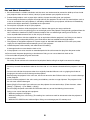
Portable LCD Projector
Model 8761A
Operation Guide
Important Information
Safety Cautions
Precautions
Please read this manual carefully before using your Projector and keep the manual handy for future
reference. Your serial number is located on the bottom of your projector. Record it here:
CAUTION
To turn off main power, be sure to remove the plug from power outlet.
The power outlet socket should be installed as near to the equipment as possible, and should be easily
accessible.
CAUTION
TO PREVENT SHOCK, DO NOT OPEN THE CABINET.
NO USER-SERVICEABLE PARTS INSIDE.
REFER SERVICING TO QUALIFIED SERVICE PERSONNEL.
This symbol warns the user that uninsulated voltage within the unit may be sufficient to cause electrical
shock. Therefore, it is dangerous to make any kind of contact with any part inside of the unit.
This symbol alerts the user that important information concerning the operation and maintenance of this
unit has been provided.
The information should be read carefully to avoid problems.
WARNING: TO PREVENT FIRE OR SHOCK, DO NOT EXPOSE THIS UNIT TO RAIN OR MOISTURE.
DO NOT USE THIS UNIT’S PLUG WITH AN EXTENSION CORD OR IN AN OUTLET UNLESS ALL THE PRONGS
CAN BE FULLY INSERTED.
DO NOT OPEN THE CABINET. THERE ARE HIGH-VOLTAGE COMPONENTS INSIDE. ALL SERVICING MUST
BE DONE BY QUALIFIED SERVICE PERSONNEL.
DOC Compliance Notice (for Canada only)
This Class B digital apparatus meets all requirements of the Canadian Interference-Causing Equipment Regulations.
Acoustic Noise Information Ordinance-3. GSGV (for Germany only):
The sound pressure level is less than 70 dB (A) according to ISO 3744 or ISO 7779.
CAUTION
Do not look into the laser pointer while it is on and do not point the
laser beam at a person. Serious injury could result.
This label is underneath the remote control.
WARNING TO CALIFORNIA RESIDENTS:
Handling the cables supplied with this product, will expose you to lead, a chemical known to the State of California
to cause birth defects or other reproductive harm. Wash hands after handling.
i
Important Information
RF Interference (for USA only)
WARNING
The Federal Communications Commission does not allow any modifications or changes to the unit EXCEPT those
specified by Dukane Corporation. in this manual. Failure to comply with this government regulation could
void your right to operate this equipment. This equipment has been tested and found to comply with the limits for a
Class B digital device, pursuant to Part 15 of the FCC Rules. These limits are designed to provide reasonable
protection against harmful interference in a residential installation. This equipment generates, uses, and can radiate radio frequency energy and, if not installed and used in accordance with the instructions, may cause harmful
interference to radio communications. However, there is no guarantee that interference will not occur in a particular
installation.
If this equipment does cause harmful interference to radio or television reception, which can be determined by
turning the equipment off and on, the user is encouraged to try to correct the interference by one or more of the
following measures:
• Reorient or relocate the receiving antenna.
• Increase the separation between the equipment and receiver.
• Connect the equipment into an outlet on a circuit different from that to which the receiver is connected.
• Consult the dealer or an experienced radio / TV technician for help.
For UK only: In UK, a BS approved power cable with moulded plug has a Black (five Amps) fuse installed for use with
this equipment. If a power cable is not supplied with this equipment please contact your supplier.
Important Safeguards
These safety instructions are to ensure the long life of your projector and to prevent fire and shock. Please read them
carefully and heed all warnings.
Installation
1. For best results, use your projector in a darkened room.
2. Place the projector on a flat, level surface in a dry area away from dust and moisture.
3. Do not place your projector in direct sunlight, near heaters or heat radiating appliances.
Exposure to direct sunlight, smoke or steam can harm internal components.
4. To avoid premature lamp failure, do not tilt the front of the projector up or down by more than 7° from level.
5. Handle your projector carefully. Dropping or jarring can damage internal components.
6. Do not place heavy objects on top of the projector.
7. If you wish to have the projector installed on the ceiling:
a. Do not attempt to install the projector yourself.
b. The projector must be installed by qualified technicians in order to ensure proper operation and reduce the
risk of bodily injury.
c. In addition, the ceiling must be strong enough to support the projector and the installation must be in accordance with any local building codes.
d. Please consult your dealer for more information.
ii
Important Information
Fire and Shock Precautions
1. Ensure that there is sufficient ventilation and that vents are unobstructed to prevent the build-up of heat inside
your projector. Allow at least 4 inches (10 cm) of space between your projector and a wall.
2. Prevent foreign objects such as paper clips and bits of paper from falling into your projector.
Do not attempt to retrieve any objects that might fall into your projector. Do not insert any metal objects such as
a wire or screwdriver into your projector. If something should fall into your projector, disconnect it immediately
and have the object removed by a qualified service personnel.
3. Do not place any liquids on top of your projector.
4. Do not look into the lens while the projector is on. Serious damage to your eyes could result.
5. Keep any items such as magnifying glass out of the light path of the projector. The light being projected from the
lens is extensive, therefore any kind of abnormal objects that can redirect light coming out of the lens, can
cause unpredictable outcome such as fire or injury to the eyes.
6. Do not cover the lens with the supplied lens cap or equivalent while the projector is on. Doing so can lead to
melting of the cap and possibly burning your hands due to the heat emitted from the light output.
7. The projector is designed to operate on a power supply of 100-240V AC 50/60 Hz. Ensure that your power
supply fits this requirement before attempting to use your projector.
8. Handle the power cable carefully and avoid excessive bending.
A damaged cord can cause electric shock or fire.
9. If the projector is not to be used for an extended period of time, disconnect the plug from the power outlet.
10. Do not touch the power plug during a thunderstorm. Doing so can cause electrical shock or fire.
11. Do not handle the power plug with wet hands.
12. When using a LAN cable:
For safety, do not connect to the connector for peripheral device wiring that might have excessive voltage.
CAUTION
• Do not try to touch the ventilation outlet on the front side as it can become heated while the projector is turned
on.
• Do not use the tilt-foot for purposes other than originally intended. Misuses such as gripping the tilt-foot or
hanging on the wall can cause damage to the projector.
• Before putting the projector in the soft case, be sure to retract the feet. Failure to do so may cause the damage
to the projector.
• Do not send the projector in the soft case by parcel delivery service or cargo shipment. The projector inside
the soft case could be damaged.
• Select [High] in Fan mode if you continue to use the projector for consecutive days. (From the menu, select
[Setup] → [Options] → [Fan Mode] → [High].)
• Do not unplug the power cable from the wall outlet under any one of the following circumstances.
Doing so can cause damage to the projector:
* While the projector's lamp lights.
* While the cooling fans are running. (The cooling fans continue to work for 90 seconds after the projector is
turned off).
* While the PC CARD Access Indicator lights. Doing so can damage your PC memory card.
iii
1. Introduction
� What's in the Box?
Make sure your box contains everything listed. If any pieces are missing, contact your dealer.
Please save the original box and packing materials if you ever need to ship your Projector.
Projector
Soft case
(24BS7114)
Lens cap
(24FT9351)
Remote control
(7N900491)
Batteries (AAA ⳯ 2)
Power cable
(7N080204) US
(7N080003) EU
Remote mouse receiver
(7N900561)
RGB/VGA signal cable
(7N520032)
• Security sticker
e
id
Gu
CD-ROM
User’s manual and User Supportware 2
Operation Guide
1
1. Introduction
� Introduction to the Projector
This section introduces you to the 8761A Projector and describes key features and controls.
Congratulations on Your Purchase of the 8761A Projector
The Projector is a sophisticated XGA projector that produces an enhanced display. With the model 8761A you will
be able to project images up to 500” (measured diagonally). Enjoy crisp and sharp large screen display from your PC,
workstation or Macintosh computer, DVD player, VCR, satellite hookup, HDTV source, ) and images from your digital
camera PC Card, compact flash memory or USB storage device. The 8761A provides for enhanced security
options to help deter projector theft and provides for full projector control through the PC control port (mini DIN 8Pin)
and LAN support. With input and output flexibility, long lamp life and a full function remote, the 8761A lets you
enjoy larger than life viewing from a compact and easy to setup and use projector.
Features you’ll enjoy on the 8761A:
•
Automatic vertical keystone correction for fast and easy application setup.
•
3D Reform™ enhanced image technology for increased projector placement versatility that provides for
horizontal, vertical and diagonal keystone correction.
•
Built-in Wall Color Correction presets provide for adaptive color correction when projecting onto non-white
screen material (or a wall).
•
USB memory or PC card interfaces provide for computer-free presentations.
•
Enhanced smart security settings for password protection, cabinet control panel lock, menu lock and PC card
protection key to help prevent unauthorized access, adjustments and theft deterrence.
•
High resolution display - up to UXGA compatible, XGA native resolution.
•
Variable audio out control of external amplified speakers via the projector remote.
•
Extensive user adjustable picture and color management settings.
•
Display 16:9 or 4:3 aspect ratio sources and fill the screen.
•
HDTV (1080i, 720p) and SDTV (480p/576p, 480i/576i) compatibility.
•
Digital photo viewer to display larger than life images from your digital cameras PC card, compact flash card or
USB storage device.
•
Integrated RJ-45 connector for wired networking capability.
•
Wireless networking capable.
Present from anywhere in the room when using as a wireless LAN projector, no physical signal cable connection to a PC is required.
* The optional wireless LAN card is required (NWL-100).
•
Supplied User Supportware 2 CD-ROM containing five software utilities allowing you to make the most of your
projector.
•
The supplied wireless remote control and remote mouse receiver allows you to operate your PC mouse wireless
from across the room. The remote mouse receiver supports most PCs with USB interface.
•
Easy set up, use and operation.
•
Eco-mode lamp technology for increased lamp life, reduced energy consumption and overall total cost of
ownership savings.
•
Built-in laser pointer on the supplied remote control allows you to draw your audience's attention in a presentation.
2
Introduction
A detailed
"User's
Manual"
is available
the CD.
Thank
you for
purchasing
the NEC
full-color on
projector
LT265/LT245 (hereafter referred to as
the "LT265/LT245" or "projector").
The projector is equipped with the following features so that you can give effective presentations.
• LAN port (RJ-45), USB port (type A), PC card slot (TYPE II) supplied as standard
• Viewer that displays images from a flash memory card*1 and USB memory*1
• Wireless LAN card supplied as an option*2
*1
The projector is not supplied with a flash memory card or USB memory.
*2
For a list of countries where NEC's optional wireless LAN card (NWL-100 series) is available, refer to the Service Page for NEC Projectors (http://www.nec-pj.com).
The projector is also supplied with User Supportware 2 CD-ROM in which five programs of
software are stored for effective use of these features. The software stored on this CDROM are as follows.
Each program runs on Windows XP and Windows 2000.
•
•
•
•
•
Image Express Utility 2.0
Desktop Control Utility 1.0
Ulead Photo Explorer 8.0 SE Basic
Viewer PPT Converter 3.0
PC Control Utility 3.0
This document explains the basic operations of the above equipment and functions. For
details of operations, refer to help function of the software.
For the network settings on the personal computer, refer to the User's Manual for the personal computer or the peripheral equipment for the network.
Use a wireless LAN card conforming to the Wi-Fi standard for your personal computer.
NOTES
(1) The contents of this guide may not be reprinted in part or whole without permission.
(2) The contents of this guide are subject to change without notice.
(3) Great care has been taken in the preparation of this guide; however, should you notice
any questionable points, errors or omissions, please contact us.
(4) Notwithstanding article (3), Dukane will not be responsible for any claims on loss of profit
or other matters deemed to result from using the Projector.
(5) Guides with incorrect collating or missing pages will be replaced.
3
1. Introduction
� Part Names of the Projector
Controls
(See page 7)
Zoom Lever
(See page 32)
Focus Ring
(See page 32)
Built-in Security Slot (
)*
Remote Sensor
(See page 12)
Ventilation (inlet)
Ventilation (outlet)
Heated air is exhausted
from here.
Carrying Handle
Adjustable Tilt Foot Lever
(See page 31)
Lens
Adjustable Tilt Foot
(See page 31)
*
Lens Cap
This security slot supports the MicroSaver® Security System. MicroSaver® is a registered trademark of
Kensington Microware Inc. The logo is trademarked and owned by Kensington Microware Inc.
Carrying the Projector
Always carry your projector by the handle.
Ensure that the power cable and any other cables connecting to video sources are disconnected before moving the
projector.
When moving the projector or when it is not in use, cover the lens with the lens cap.
4
1. Introduction
Monaural Speaker (2W)
PC Card Eject Button
PC Card Slot
Lamp cover
(See page 119)
Ventilation (outlet)
Remote Sensor
(See page 12)
Lamp cover screw
Rear Foot
AC Input
Connect the supplied power cable's
three-pin plug here, and plug the other
end into an active wall outlet.
(See page 26)
Rear Foot
Rotate to make the projector level.
(See page 31)
Main Power Switch
When you plug the supplied power cable into an active wall
outlet and turn on the Main Power switch, the POWER
indicator turns orange and the projector is in standby mode.
(See page 28)
5
1. Introduction
Top Features
9
4
10
5 11
MEN U
SOURCE
AUTO ADJUST
SELECT
LAMP
STATUS
EN
TE
R
EX
IT
3D REFORM
ON/STAND BY
2
POWER
PC CARD
6
7
8
12
6. PC CARD Access Indicator
1. POWER Button (ON / STAND BY)
Lights while accessing a PC card.
Use this button to turn the power on and off when the
main power is supplied and the projector is in standby
mode.
NOTE: To turn on the projector, press and hold this button
for a minimum of two seconds. To turn off the projector,
press this button twice.
7. ENTER Button
Executes your menu selection and activates items
selected from the menu.
8. EXIT Button
2. STATUS Indicator
Pressing this button will return to the previous menu
with saving changes.
While you are in the main menu, pressing this button
will close the menu.
If this light blinks red rapidly, it indicates that an error
has occurred, the lamp cover is not attached properly
or the projector has overheated. If this light remains
orange, it indicates that you have pressed a cabinet
key while the Cabinet Button Lock is enabled. See the
Status Indicator section on page 123 for more details.
3. POWER Indicator (
1 3
9. SELECT 왖왔왗왘 (+) (–) / Volume Buttons
왖왔 : Use these buttons to select the menu of the
item you wish to adjust.
)
When this indicator is green, the projector is on; when
this indicator is orange, it is in standby mode. See the
Power Indicator section on page 123 for more details.
왗왘 : Use these buttons to change the level of a
selected menu item. When no menus appear,
these buttons work as a volume control.
When the pointer is displayed, these 왖왔왗왘 buttons
move the pointer.
4. SOURCE Button
Use this button to select a video source such as a PC,
VCR, DVD player or Viewer (PC card).
Press and release this button quickly to display the
Source List.
10. MENU Button
Each time this button is pressed for a minimum of ONE
second, the input source will change as follows:
11. LAMP Indicator
Displays the menu.
If this light blinks red rapidly, it's warning you that the
projection lamp has exceeded 2000 hours (up to 4000
hours in Eco mode) of service. After this light appears,
replace the lamp as soon as possible. (See page 119).
If this is lit green continually, it indicates that the lamp
mode is set to Eco. See the Lamp Indicator section
on page 123 for more details.
Computer1 → Computer2 → Video → S-Video →
Viewer → Computer1 → ...
If no input signal is present, the input will be skipped.
5. AUTO ADJUST Button
12. 3D REFORM Button
Use this button to adjust an RGB source for an optimal picture.
Press this button to enter 3D Reform mode to correct
the keystone (trapezoidal) distortion, and make the
image square.
6
1. Introduction
Terminal Panel Features
13
12 11 10
9 3 5
AUDIO OUT
PC CARD
LAN USB
R AUDIO IN L
VIDEO IN
8
7
S-VIDEO IN PC CONTROL COMPUTER 1 IN AUDIO IN
6
1
COMPUTER 2 IN
2
MONITOR OUT
4
6. S-VIDEO IN Connector (Mini DIN 4 Pin)
1. COMPUTER 1 IN / Component Input Connector
(Mini D-Sub 15 Pin)
Here is where you connect the S-Video input from an
external source like a VCR.
NOTE: S-Video provides more vivid color and higher
resolution than the traditional composite video format.
Connect your computer or other analog RGB equipment such as IBM compatible or Macintosh computers. Use the supplied RGB/VGA signal cable to connect to your computer. This also serves as a component input connector that allows you to connect a component video output of component equipment such
as a DVD player. This connector also supports SCART
output signal. See page 18 for more details.
7. VIDEO IN Connector (RCA)
Connect a VCR, DVD player, laser disc player, or document camera here to project video.
8. VIDEO AUDIO IN Jacks (RCA)
2. COMPUTER 2 IN / Component Input Connector
(Mini D-Sub 15 Pin)
L: This is your left channel audio input for stereo
sound coming from the VIDEO source.
R: This is your right channel audio input for stereo
sound from the VIDEO source.
This connector has the same function as the COMPUTER 1 IN connector.
NOTE: The COMPUTER 2 IN does not support SCART
output signal and Plug & Play.
9. PC CONTROL Port (Mini DIN 8 Pin)
Use this port to connect your PC or control system to
control your projector via a serial cable. This enables
you to control the projector using serial communication protocol. The optional serial cable (CA03D)
is required to use this port. You can also control the
projector by using PC Control Utility 3.0 contained on
the supplied User Supportware 2 CD-ROM.
To do so you must first have PC Control Utility 3.0
installed on your PC. If you are writing your own program, typical PC control codes are on page 131.
3. COMPUTER AUDIO IN Mini Jack (Stereo Mini)
This is where you connect audio output from your computer or DVD player. A commercially available audio
cable is required.
4. MONITOR OUT Connector (Mini D-Sub 15 Pin)
You can use this connector to loop your computer
image to an external monitor from the COMPUTER 1
or 2 input source.
The RGB analog signal set on “OUT Terminal” is output during Standby mode. See pages 19 and 109.
10. USB Port (Type A)
Connect a commercially available USB memory device or mouse that supports USB. You can operate
the menu or Viewer with the USB mouse via this port.
Note that this port should not be connected to a computer and that there may be some brands of USB
mouse that the projector does not support.
5. AUDIO OUT Mini Jack (Stereo Mini)
Connect an additional audio equipment here to listen
to audio coming from your computer, Video or S- Video
input.
• Output sound level can be adjusted in accordance
with the sound level of the internal speaker.
11. LAN Port (RJ-45)
• When audio equipment is connected, the projector speaker is disabled.
This port is typically used for UTP Ethernet/Fast
Ethernet. Use this connector to control the projector
on a LAN. See page 22.
• This jack cannot be used as a headphone jack.
7
1. Introduction
Terminal Panel Features
13
12 11 10
9 3 5
AUDIO OUT
PC CARD
LAN USB
R AUDIO IN L
VIDEO IN
8
7
S-VIDEO IN PC CONTROL COMPUTER 1 IN AUDIO IN
6
1
12. PC CARD Eject Button
Press to eject a PC card partially.
13. PC CARD Slot
Insert a PC memory card or optional wireless
LAN card here.
8
COMPUTER 2 IN
2
MONITOR OUT
4
1. Introduction
쐏 Part Names of the Remote Control
1. Infrared Transmitter/Laser Pointer
Transmits an infrared signal when any button other
than LASER is pressed.
Direct the remote control toward the remote sensor
on the projector cabinet.
Beams a laser light when the Laser button is pressed.
1
2
4
OFF
3
6
8
ON
POWER
MAGNIFY
LASER
PAGE
UP
5
7
9
POINTER
CAUTION:
* Do not look into the laser pointer while it is on.
* Do not point the laser beam at a person.
DOWN
10
11
12
2. LED
Flashes when any button is pressed.
13
15
16
18
21
17
20
26
3. POWER ON Button
When the main power is on, you can use this button
to turn your projector on.
NOTE: To turn on the projector, press and hold the
POWER ON button for a minimum of two seconds.
22
24
23
VIDEO
COMPUTER
LAN
1
S-VIDEO
VIEWER
2
PIC-MUTE
AUTO ADJ.
VOLUME
HELP
ASPECT
FREEZE
SLIDE
27
19
28
29
PICTURE
3D REFORM
4. POWER OFF Button
You can use this button to turn your projector off.
NOTE: To turn off the projector, press the POWER
OFF button twice.
5. MAGNIFY (+)(–) Buttons
Use these buttons to adjust the image size.
The image can be magnified about the center of the
screen up to 400%. See page 40.
25
6. LASER Button
Press and hold this button to activate the laser pointer.
When lit, you can use the laser to draw your audience's
attention to a red dot that you can place on any object.
14
7. POINTER Button
Press this button to display the projector pointer. You
can move your pointer icon to the area you want on
the screen using the Select button. See page 39.
8. PAGE UP/DOWN Buttons
Use these buttons to operate your computer with the
supplied remote mouse receiver. You can use these
buttons to scroll the viewing area of the window or to
move to the previous or next slide in PowerPoint on
your computer.
9. MENU Button
Displays the menu for various settings and adjustments.
9
1. Introduction
10. Select Button
This button is used for projector’s menu operation and
moving the magnified image.
This button also works as a computer mouse when
the supplied remote mouse receiver is connected with
your computer. See page 42.
23. FREEZE Button
This button will freeze a picture. Press again to resume motion. See page 39.
11. ENTER Button
Executes your menu selection and activates items
selected from the menu.
25. ASPECT Button
Press this button to display the Aspect Ratio select
menu. See page 81.
12. EXIT Button
Returns to the previous menu.
While you are in the main menu, pressing this button
will close the menu.
26. VIEWER Button
Press this button to select the Viewer source. See page
64.
24. HELP Button
Provides the Information screen. See page 40.
27. SLIDE +/- Buttons
Press (+) to select the next folder or slide and press
(–) to select the previous folder or slide.
13. R-CLICK Button
Works as the mouse right button when the supplied
remote mouse receiver is connected with your computer.
28. PICTURE Button
Press to display the picture adjustment screen. Pressing this button sequentially selects "Brightness" →
"Contrast" → "Color" → "Hue" → "Sharpness" → "Wall
Color". See pages 79 and 80.
14. L-CLICK Button
Works as the mouse left button when the supplied
remote mouse receiver is connected with your computer.
29. 3D REFORM Button
Press this button to enter 3D Reform to correct the
keystone (trapezoidal) distortion, and make the image square. See pages 33 and 43.
15. VIDEO Button
Press this button to select a video source from a VCR,
DVD player, laser disc player or document camera.
16. S-VIDEO Button
Press this button to select an S-Video source from a
VCR.
17. COMPUTER 1 Button
Press this button to select COMPUTER 1 input.
18. COMPUTER 2 Button
Press this button to select COMPUTER 2 input.
19. AUTO ADJ. Button
Use this button to adjust an RGB source (COMPUTER
1 or 2) for an optimal picture. See page 35.
20. LAN Button
Press this button to select the LAN (Local Area Network) connection.
21. PIC-MUTE Button
This button turns off the image and sound for a short
period of time. Press again to restore the image and
sound. See page 39.
22. VOLUME +/– Buttons
Press (+) to increase the volume and (–) to decrease
it. See page 35.
10
1. Introduction
Battery Installation
1 Remove the battery cover.
2 Remove both old batteries and
NOTE: Do not pull the battery
cover by force. Doing so can
result in it coming off.
install new ones (AAA). Ensure
that you have the batteries' polarity (+/ –) aligned correctly.
3 Slip the cover back over the batteries until it snaps into place.
NOTE: Do not mix different types of
batteries or new and old batteries.
2
1
1
2
Operating Range for Wireless Remote Control
7m/22 feet
7m/22 feet
30°
30°
30°
Remote control
30°
Remote sensor on projector cabinet
• The infrared signal operates by line-of-sight up to a distance of about 22 feet/7 m and within a 60-degree angle of
the remote sensor on the projector cabinet.
• The projector will not respond if there are objects between the remote control and the sensor, or if strong light falls
on the sensor.
Weak batteries will also prevent the remote control from properly operating the projector.
Remote Control Precautions
•
•
•
•
•
•
•
Handle the remote control carefully.
If the remote control gets wet, wipe it dry immediately.
Avoid excessive heat and humidity.
If you will not be using the remote control for a long time, remove the batteries.
Do not place the batteries upside down.
Do not use new and old batteries together, or use different types of batteries together.
Dispose of used batteries according to your local regulations.
11
2. Installation and Connections
This section describes how to set up your projector and how to connect PCs, video and audio sources.
Your projector is simple to set up and use.
But before you get started, you must first:
1
z Set up a screen and the projector.
x Connect your computer or video equipment to the projector. See pages 17 25.
c Connect the supplied power cable. See
page 26.
2
3
NOTE: Ensure that the power cable and any
other cables are disconnected before moving
the projector. When moving the projector or
when it is not in use, cover the lens with the
lens cap.
To the wall outlet.
� Setting Up the Screen and the Projector
Selecting a Location
The further your projector is from the screen or wall, the larger the image. The minimum size the image can be is
approximately 30 inches (0.8 m) measured diagonally when the projector is roughly 51.2 inches (1.3 m) from the wall
or screen. The largest the image can be is 500 inches (12.7 m) when the projector is about 970 inches (24.6 m) from
the wall or screen. Use the drawing below as a guide.
Screen size (Unit: cm/inch)
609.6 (W) ⳯ 457.2 (H) / 240 (W) ⳯ 180 (H)
30
0"
Screen size
487.7 (W) ⳯ 365.8 (H) / 192 (W) ⳯ 144 (H)
24
0"
406.4 (W) ⳯ 304.8 (H) / 160 (W) ⳯ 120 (H)
20
365.8 (W) ⳯ 274.3 (H) / 144 (W) ⳯ 108 (H)
0"
18
0"
304.8 (W) ⳯ 228.6 (H) / 120 (W) ⳯ 90 (H)
15
0"
243.8 (W) ⳯ 182.9 (H) / 96 (W) ⳯ 72 (H)
12
)
(1
0
2
13 9.5
.4 )
/5
28
.0
80
"
4
1
(1 .3
.0 /50
/
1 39 .8
(1 .7 .5
.4 /6 )
/5 8.
3. 5
3)
3.
2
5/ (2 .6/1
13 .1/ 0
4. 9. 80. 3.8
4 2 9)
30 0"
"
/1 (2
74 .8
. /1
5. 5 ( 08.
3/ 3. 6)
20 5/
9. 13
9 6.
( 2
6. 4.2 )
7/ /1
26 6
2. 3.8
9 )
(
8. 5.2
0/ /2
31 05
5 .2
8. .9 )
9/ (6
35 .3
1. /24
3 6
D
(7 .7
is
ta 10 .0/2 )
nc .7/ 74.
e 422 3)
.0
(8
.
60
4/
3
"
121.9 (W) ⳯ 91.4 (H) / 48 (W) ⳯ 36 (H)
81.3 (W) ⳯ 61.0 (H) / 32 (W) ⳯ 24 (H)
Lens center
.5
/4
0"
162.6 (W) ⳯ 121.9 (H) / 64 (W) ⳯ 48 (H)
61.0 (W) ⳯ 45.7 (H) / 24 (W) ⳯ 18 (H)
0"
10
12
.4
203.2 (W) ⳯ 152.4 (H) / 80 (W) ⳯ 60 (H)
Unit: m/inch
NOTE:
• Values in parentheses for 8760A
•The screen sizes above are intermediate values between tele (minimum display area) and wide (maximum display area). Image
size can be adjusted with the zoom adjustment up to a maximum of 10%.
• To avoid premature lamp failure, do not tilt the front of the projector up or down by more than 7° from level.
12
2. Installation and Connections
Throw Distance and Screen Size
Screen Width
The following shows the proper relative positions of the projector and screen. Refer to the table to determine the position of installation.
Screen Diagonal
Screen Height
Distance Chart
Screen center
B = Vertical distance between lens center and screen center
C = Throw distance
D = Vertical distance between lens center and bottom of
screen (top of screen for ceiling application)
α = Throw angle
(B)
Screen Bottom
(D)
Lens Center
NOTE: Distances may vary +/-5%.
Throw Angle (움)
Throw Distance (C)
8761A
LT265
Diagonal
inch
30
40
60
67
72
80
84
90
100
120
150
180
200
210
240
261
270
300
350
400
450
500
Screen Size
Width
inch
24
32
48
54
58
64
67
72
80
96
120
144
160
168
192
209
216
240
280
320
360
400
B
Height
inch
18
24
36
40
43
48
50
54
60
72
90
108
120
126
144
157
162
180
210
240
270
300
inch
12.6
16.8
25.2
28.1
30.2
33.6
35.3
37.8
42.0
50.4
63.0
75.6
84.0
88.2
100.8
109.7
113.5
126.1
147.1
168.1
189.1
210.1
C
Wide – Tele
inch
45.6 – 56.0
61.5 – 75.4
93.5 – 114.1
104.7 – 127.7
112.7 – 137.4
125.5 – 152.9
131.9 – 160.6
141.5 – 172.2
157.4 – 191.6
189.4 – 230.3
237.3 – 288.4
285.3 – 346.6
317.2 – 385.3
333.2 – 404.7
381.2 – 462.8
414.7 – 503.4
429.1 – 520.9
477.0 – 579.0
557.0 – 675.8
636.9 – 772.7
716.8 – 869.5
796.7 – 966.4
D
inch
3.6
4.8
7.2
8.0
8.6
9.6
10.1
10.8
12.0
14.4
18.0
21.6
24.0
25.2
28.8
31.4
32.5
36.1
42.1
48.1
54.1
60.1
α
Wide – Tele
degree
15.4 – 12.7
15.3 – 12.6
15.1 – 12.5
15.0 – 12.4
15.0 – 12.4
15.0 – 12.4
15.0 – 12.4
15.0 – 12.4
14.9 – 12.4
14.9 – 12.3
14.9 – 12.3
14.8 – 12.3
14.8 – 12.3
14.8 – 12.3
14.8 – 12.3
14.8 – 12.3
14.8 – 12.3
14.8 – 12.3
14.8 – 12.3
14.8 – 12.3
14.8 – 12.3
14.8 – 12.3
Screen Size
Diagonal
Width
inch
mm
mm
762
610
30
813
40
1016
60
1524
1219
1702
1361
67
1463
72
1829
80
2032
1626
2134
1707
84
1829
90
2286
100
2540
2032
3048
2438
120
3048
150
3810
180
4572
3658
5080
4064
200
4267
210
5334
240
6096
4877
6629
5304
261
5486
270
6858
300
7620
6096
8890
7112
350
8128
400 10160
450 11430
9144
500 12700 10160
Height
mm
457
610
914
1021
1097
1219
1280
1372
1524
1829
2286
2743
3048
3200
3658
3978
4115
4572
5334
6096
6858
7620
α
Wide – Tele
degree
19.4 – 16.2
19.1 – 16.0
18.9 – 15.9
18.9 – 15.8
18.8 – 15.8
18.8 – 15.8
18.8 – 15.8
18.8 – 15.8
18.7 – 15.7
18.7 – 15.7
18.7 – 15.7
18.6 – 15.7
18.6 – 15.7
18.6 – 15.7
18.6 – 15.6
18.6 – 15.6
18.6 – 15.6
18.6 – 15.6
18.6 – 15.6
18.6 – 15.6
18.5 – 15.6
18.5 – 15.6
Screen Size
Diagonal
Width
inch
mm
mm
762
610
30
813
40
1016
60
1524
1219
1702
1361
67
1463
72
1829
80
2032
1626
2134
1707
84
1829
90
2286
100
2540
2032
3048
2438
120
3048
150
3810
4572
3658
180
5080
4064
200
4267
210
5334
6096
4877
240
6629
5304
261
5486
270
6858
7620
6096
300
8890
7112
350
8128
400 10160
9144
450 11430
500 12700 10160
Height
mm
457
610
914
1021
1097
1219
1280
1372
1524
1829
2286
2743
3048
3200
3658
3978
4115
4572
5334
6096
6858
7620
B
mm
320
427
640
714
768
853
896
960
1067
1280
1601
1921
2134
2241
2562
2786
2882
3202
3736
4270
4804
5337
C
Wide – Tele
mm
1,157 – 1,423
1,563 – 1,915
2,375 – 2,899
2,659 – 3,243
2,862 – 3,489
3,187 – 3,883
3,349 – 4,080
3,593 – 4,375
3,999 – 4,867
4,811 – 5,851
6,028 – 7,327
7,246 – 8,802
8,058 – 9,786
8,464 –10,278
9,682 –11,754
10,534 –12,787
10,899 –13,230
12,117 –14,706
14,147 –17,166
16,176 –19,626
18,206 –22,086
20,235 –24,545
D
mm
91
122
183
204
219
244
256
274
305
366
458
549
610
641
733
797
824
916
1069
1222
1375
1527
α
Wide – Tele
degree
15.4 – 12.7
15.3 – 12.6
15.1 – 12.5
15.0 – 12.4
15.0 – 12.4
15.0 – 12.4
15.0 – 12.4
15.0 – 12.4
14.9 – 12.4
14.9 – 12.3
14.9 – 12.3
14.8 – 12.3
14.8 – 12.3
14.8 – 12.3
14.8 – 12.3
14.8 – 12.3
14.8 – 12.3
14.8 – 12.3
14.8 – 12.3
14.8 – 12.3
14.8 – 12.3
14.8 – 12.3
8760A
LT245
Diagonal
inch
30
40
60
67
72
80
84
90
100
120
150
180
200
210
240
261
270
300
350
400
450
500
Screen Size
Width
inch
24
32
48
54
58
64
67
72
80
96
120
144
160
168
192
209
216
240
280
320
360
400
B
Height
inch
18
24
36
40
43
48
50
54
60
72
90
108
120
126
144
157
162
180
210
240
270
300
inch
12.5
16.7
25.1
28.1
30.2
33.5
35.2
37.7
41.9
50.3
62.9
75.5
83.9
88.1
100.7
109.5
113.3
125.9
146.9
167.9
188.9
209.9
C
Wide – Tele
inch
35.7 – 43.3
48.2 – 58.4
73.3 – 88.5
82.1 – 99.1
88.4 – 106.6
98.5 – 118.7
103.5 – 124.7
111.0 – 133.7
123.6 – 148.8
148.7 – 178.9
186.3 – 224.1
224.0 – 269.3
249.1 – 299.5
261.7 – 314.5
299.3 – 359.7
325.7 – 391.4
337.0 – 405.0
374.6 – 450.2
437.4 – 525.5
500.2 – 600.8
563.0 – 676.2
625.7 – 751.5
D
inch
3.5
4.7
7.1
8.0
8.6
9.5
10.0
10.7
11.9
14.3
17.9
21.5
23.9
25.1
28.7
31.2
32.3
35.9
41.9
47.9
53.9
59.9
13
B
mm
319
425
639
713
766
852
894
958
1065
1278
1598
1918
2132
2238
2558
2782
2878
3198
3731
4264
4798
5331
C
Wide – Tele
mm
906 – 1,100
1,225 – 1,483
1,863 – 2,248
2,086 – 2,516
2,246 – 2,707
2,501 – 3,014
2,628 – 3,167
2,820 – 3,396
3,139 – 3,779
3,776 – 4,545
4,733 – 5,693
5,689 – 6,841
6,327 – 7,607
6,646 – 7,989
7,603 – 9,137
8,272 – 9,941
8,559 –10,286
9,516 –11,434
11,110 –13,348
12,705 –15,261
14,299 –17,175
15,893 –19,089
D
mm
90
120
181
203
218
242
254
273
303
364
455
547
608
638
729
793
821
912
1064
1216
1369
1521
α
Wide – Tele
degree
19.4 – 16.2
19.1 – 16.0
18.9 – 15.9
18.9 – 15.8
18.8 – 15.8
18.8 – 15.8
18.8 – 15.8
18.8 – 15.8
18.7 – 15.7
18.7 – 15.7
18.7 – 15.7
18.6 – 15.7
18.6 – 15.7
18.6 – 15.7
18.6 – 15.6
18.6 – 15.6
18.6 – 15.6
18.6 – 15.6
18.6 – 15.6
18.6 – 15.6
18.5 – 15.6
18.5 – 15.6
2. Installation and Connections
• Ensure that you have adequate ventilation around your
projector so heat can dissipate. Do not cover the vents
on the side or the front of the projector.
WARNING
* Installing your projector on the ceiling must be done
by a qualified technician. Contact your dealer for
more information.
* Do not attempt to install the projector yourself.
• Only use your projector on a solid, level surface. If the
projector falls to the ground, you can be injured and
the projector severely damaged.
• Do not use the projector where temperatures vary
greatly. The projector must be used at temperatures
between 41˚F (5˚C) and 95˚F (35˚C).
• Do not expose the projector to moisture, dust, or
smoke. This will harm the screen image.
Reflecting the Image
Using a mirror to reflect your projector's image enables
you to enjoy a much larger image. Contact your NEC
dealer if you need a mirror system. If you're using a mirror system and your image is inverted, use the MENU
and SELECT buttons on your projector cabinet or your
remote control to correct the orientation. See page 98.
14
7. Maintenance
This section describes the simple maintenance procedures you should follow to replace the lamp, and to clean the
cabinet and the lens.
쐃 Cleaning the Cabinet
1. Turn off the projector before cleaning.
2. Clean the cabinet periodically with a damp cloth. If heavily soiled, use a mild detergent. Never use strong
detergents or solvents such as alcohol or thinner.
쐇 Cleaning the Lens
Use a blower or lens paper to clean the lens, and be careful not to scratch the lens.
Lens Protector
The lens barrel has threads on the outside for mounting a commercially available step-up ring (φ77mm → φ82mm) and
lens protector (φ82mm) to protect the lens from dirt, dust, scratches and damage. Note that both a lens protector and
the supplied lens cap cannot be used at the same time.
CAUTION: Use only transparent lens protectors designed for lens protection.
Use of filters for light reduction and special effects, such as ND (Neutral Density) filters and color filters, can
absorb heat, resulting in damage to the filter and the projector.
15
7. Maintenance
� Replacing the Lamp
After your lamp has been operating for 2000 hours (up to 4000 hours : Eco mode) or longer, the "Lamp" indicator in the
cabinet will blink red and the message will appear. Even though the lamp may still be working, replace it at 2000 hours
(up to 4000 hours : Eco mode) to maintain optimal projector performance.
CAUTION
•
DO NOT TOUCH THE LAMP immediately after it has been used. It will be extremely hot. Turn the projector off,
wait 90 seconds, turn off the main power switch, and then disconnect the power cable. Allow at least one hour
for the lamp to cool before handling.
•
DO NOT REMOVE ANY SCREWS except the lamp cover screw and two lamp case screws. You could receive
an electric shock.
•
Do not break the glass on the lamp housing.
Keep finger prints off the glass surface on the lamp housing. Leaving finger prints in the glass surface might
cause an unwanted shadow and poor picture quality.
•
The projector will turn off and go into stand by mode after 2100 hours (up to 4100 hours : Eco mode) of service.
If this happens, be sure to replace the lamp. If you continue to use the lamp after 2000 hours (up to 4000 hours :
Eco mode) of use, the lamp bulb may shatter, and pieces of glass may be scattered in the lamp housing. Do not
touch them as the pieces of glass may cause injury.
If this happens, contact your dealer for lamp replacement.
To replace the lamp:
1. Loosen the lamp cover screw until the screwdriver goes into a freewheeling condition and remove the
lamp cover. The lamp cover screw is not removable.
2. Loosen the two screws securing the lamp housing until the screwdriver goes into a freewheeling
condition. The two screws are not removable.
16
7. Maintenance
3. Remove the lamp housing by pulling out the handle.
NOTE: There is an interlock on this case to prevent the risk of electrical shock. Do not attempt to circumvent this interlock.
Interlock
4. Insert a new lamp housing until the lamp housing is plugged into the socket.
CAUTION
Do not use a lamp other than the specified replacement lamp (LT60LPK).
5. Secure it in place with the two screws.
Be sure to tighten the screws.
17
7. Maintenance
6. Reattach the lamp cover.
7. Tighten the lamp cover screw.
Be sure to tighten the screw.
8. After you install a new lamp, select the menu [Reset] → [Clear Lamp Hour Meter] to clear the Remaining
Lamp Time and the Lamp Hour Meter.
NOTE: When the lamp exceeds 2100 hours (up to 4100 hours in Eco mode) of service, the projector cannot turn on and the
menu is not displayed. If this happens, press the HELP button on the remote control for a minimum of 10 seconds while in
standby mode. When the lamp time clock is reset to zero, the LAMP indicator goes out.
18
8. Appendix
� Troubleshooting
This section helps you resolve problems you may encounter while setting up or using the projector.
Indicator Messages
Power Indicator
Indicator Condition
Projector Condition
Off
Blinking light
Green
0.5 sec On,
0.5 sec Off
2.5 sec On,
0.5 sec Off
0.5 sec On,
0.5 sec Off
Orange
Steady light
Green
Orange
Note
The main power is off
–
The projector is getting ready to turn on. Wait for a moment.
Off Timer is activated.
–
The projector is cooling down.
Wait for a moment.
The projector is turned on.
The projector is in Standby.
–
–
Status Indicator
Indicator Condition
Off
Blinking light
Red
Green
Orange
Steady light
Projector Condition
Normal
1 cycle (0.5 sec On, Lamp cover error
2.5 sec Off)
2 cycle (0.5 sec On, Temperature error
0.5 sec Of)
3 cycle (0.5 sec On, Power error
0.5 sec Off)
4 cycle (0.5 sec On, Fan error
0.5 sec Off)
6 cycle (0.5 sec On, Lamp error
0.5 sec Off)
Re-firing the lamp
1 cycle(0.5 sec On, Network conflict
2.5 sec Off)
Orange
Cabinet button is locked
Note
–
Replace the lamp cover correctly.
(Page 121)
The projector is overheated. Move
the projector to a cooler location.
Power unit will not work correctly.
Fans will not work correctly.
Lamp fails to light. Wait a full
minute and then turn on again.
The projector is re-firing.
Both the built-in LAN and the wireless
LAN cannot be connected to the same
network at the same time.
To use both built-in LAN and wireless
LAN at the same time, connect them to
different networks. (page 100)
You have pressed cabinet button
when Cabinet Button is locked.
(Page 93)
Lamp Indicator
Indicator Condition
Off
Blinking light
Red
Steady light
Red
Green
Projector Condition
Normal
Lamp has reached its end of life. Lamp
replacement message will be displayed.
Lamp has been used beyond its limit. The
projector will not turn on until the lamp is
replaced.
Lamp mode is set to Eco mode
19
Note
–
Replace the lamp.
(Page 119)
Replace the lamp.
(Page 119)
–
8. Appendix
Common Problems & Solutions (See also "Power/Status/Lamp Indicator" on page 123.)
Problem
Check These Items
Does not turn on
• Check that the power cable is plugged in and that the power button on the projector cabinet or the remote
control is on. See pages 26 and 28.
• Ensure that the lamp cover is installed correctly. See page 121.
• Check to see if the projector has overheated or the lamp usage exceeds 2100 hours (up to 4100 hours : Eco
mode). If there is insufficient ventilation around the projector or if the room where you’re presenting is particularly warm, move the projector to a cooler location.
• The lamp may fail to light. Wait a full minute and then turn on the power again.
• The lamp has reached the end of its usable life. Replace the lamp.
Will turn off
• Ensure that the Power Management is off. See page 107.
No picture
• Use the SOURCE button on the projector cabinet or the VIDEO, the S-VIDEO, the COMPUTER 1/2, the VIEWER
or the LAN button on the remote control to select your source. See page 30.
• Ensure your cables are connected properly.
• Use menus to adjust the brightness and contrast. See page 79.
• Remove the lens cap.
• Reset the settings or adjustments to factory preset levels using the Reset in the Menu. See page 116.
• Enter your registered keyword if the Security function is enabled. See page 48.
• When using with a notebook PC, be sure to connect between the projector and the notebook PC before turning
on the power to the notebook PC. In most cases signal cannot be output from RGB output unless the notebook
PC is turned on after connecting with the projector.
* If the screen goes blank while using your remote control, it may be the result of the computer's screensaver or power management software.
* If you accidentally hit the POWER button on the remote control, wait 90 seconds and then press the POWER
button again to resume.
• See also the next page.
Color tone or hue is
unusual
• Check if an appropriate color is selected in "Wall Color". If so, select an appropriate option. See page 80.
• Adjust "Hue" in "Adjust". See page 80.
Image isn’t square to
the screen
• Reposition the projector to improve its angle to the screen. See page 31.
• Use the 3DReform function to correct the trapezoid distortion. See page 33.
Picture is blurred
• Adjust the focus. See page 32.
• Reposition the projector to improve its angle to the screen. See page 31.
• Ensure that the distance between the projector and screen is within the adjustment range of the lens. See page
15.
• Condensation may form on the lens if the projector is cold, brought into a warm place and is then turned on.
Should this happen, let the projector stand until there is no condensation on the lens.
Image is scrolling
vertically, horizontally
or both
• Use the SOURCE button on the projector cabinet or the VIDEO, the S-VIDEO, the COMPUTER 1/2, the VIEWER
or the LAN button on the remote control to select your source (Video, S-Video, Computer, Viewer or LAN). See
page 30.
• Adjust the computer image manually with the “Clock”/“Phase” in “Adjust” → “Image Options”. See page 86.
Remote control does
not work
• Install new batteries. See page 12.
• Make sure there are no obstacles between you and the projector.
• Stand within 22 feet (7 m) of the projector. See page 12.
Indicator is lit or
blinking
• See the POWER/STATUS/LAMP Indicator.
Vertical stripes in RGB
mode
• Press the AUTO ADJUST button on the projector cabinet or the AUTO ADJ. button on the remote control. See
page 35.
• Adjust the computer image manually with the “Clock”/“Phase” in “Adjust” → “Image Options”. See page 86.
USB mouse does not
work
• Make sure that your USB mouse is properly connected to the projector.
The projector may not support some brands of a USB mouse.
Capture function is not
possible.
• The Capture function is not available on LAN. See page 30.
For more information contact your dealer.
20
8. Appendix
If there is no picture, or the picture is not displayed correctly.
•
Power on process for the projector and the PC.
Be sure to connect the RGB cable between the projector and the computer before turning on the computer.
There are some notebook PCs, which do not output signal unless there is a projector or monitor connected first.
NOTE: You can check the horizontal frequency of the current signal in the projector’s menu under Information. If it reads
“0kHz”, this means there is no signal being output from the computer. See page 113 or go to next step.
•
Enabling the computer’s external display.
Displaying an image on the notebook PC’s screen does not necessarily mean it outputs a signal to the projector. When using a PC compatible laptop, a combination of function keys will enable/disable the external display.
Usually, the combination of the ‘Fn” key along with one of the 12 function keys gets the external display to come
on or off. For example, laptops use Fn + F3, while Dell laptops use Fn + F8 key combinations to toggle
through external display selections.
•
Non-standard signal output from the computer
If the output signal from a notebook PC is not an industry standard, the projected image may not be displayed
correctly. Should this happen, deactivate the notebook PC’s LCD screen when the projector display is in use.
Each notebook PC has a different way of deactivate/reactivate the local LCD screens as described in the
previous step. Refer to your computer’s documentation for detailed information.
•
Image displayed is incorrect when using a Macintosh
When using a Macintosh with the projector, set the DIPswitch of the Mac adapter (not supplied with the projector) according to your resolution. After setting, restart your Macintosh for the changes to take affect.
For setting display modes other than those supported by your Macintosh and the projector, changing the DIP
switch on a Mac adapter may bounce an image slightly or may display nothing. Should this happen, set the DIP
switch to the 13” fixed mode and then restart your Macintosh. After that, restore the DIP switches to a
displayable mode and then restart the Macintosh again.
NOTE: A Video Adapter cable manufactured by Apple Computer is needed for a PowerBook which does not have a mini D-Sub
15-pin connector.
•
Mirroring on a PowerBook
* When using the projector with a Macintosh PowerBook, output may not be set to 1024 x 768 unless “mirroring” is off on your PowerBook. Refer to owner’s manual supplied with your Macintosh computer for mirroring.
•
Folders or icons are hidden on the Macintosh screen
Folders or icons may not be seen on the screen. Should this happen, select [View] ->[Arrange] from the Apple
menu and arrange icons.
21
8. Appendix
쐊 Troubleshooting Check List
Before contacting your dealer or service personnel, check the following list to be sure repairs are needed also by
referring to the “Troubleshooting” section in your user’s manual. This checklist below will help us solve your problem
more efficiently.
* Print the following pages.
Frequency of occurrence 䡺 always 䡺 sometimes (How often?_____________________) 䡺 other (__________________)
Power
No power (POWER indicator does not light green) See also “Status Indicator (STATUS)”.
Power cable's plug is fully inserted into the wall outlet.
Main power switch is pressed to the ON position.
Lamp cover is installed correctly .
Lamp Hour Meter (lamp operation hours) was cleared after
lamp replacement.
No power even though you press and hold the POWER button
for a minimum of 2 seconds.
Shut down during operation.
Power cable's plug is fully inserted into the wall outlet.
Lamp cover is installed correctly .
Power Management is turned off (only models with the Power
Management function).
Sleep Timer is turned off (only models with the Sleep Timer
function ).
Video and Audio
No image is displayed from your PC or video equipment to the
projector.
Still no image even though you connect the projector to the PC
first, then start the PC.
Enabling your notebook PC’s signal output to the projector.
• A combination of function keys will enable/disable the external display. Usually, the combination of the “Fn” key along
with one of the 12 function keys turns the external display
on or off.
No image (blue background, logo, no display).
Still no image even though you press the AUTO ADJUST button.
Still no image even though you carry out “Reset” in the
projector’s menu.
Signal cable's plug is fully inserted into the input connector
A message appears on the screen.
( _____________________________________________ )
The source connected to the projector is active and available.
Still no image even though you adjust the brightness and/or
the contrast.
Input source's resolution and frequency are supported by the
projector.
Parts of the image are lost.
Still unchanged even though you press the AUTO ADJUST button.
Still unchanged even though you carry out “Reset” in the
projector’s menu.
Image is too dark.
Remains unchanged even though you adjust the brightness
and/or the contrast.
Image is distorted.
Image appears to be trapezoidal (unchanged even though you
carry out the “Keystone" or “3D Reform” adjustment).
No sound.
Audio cable is correctly connected to the audio input of the
projector.
Still unchanged even though you adjusted the volume level.
AUDIO OUT is connected to your audio equipment (only models with the AUDIO OUT connector).
Image is shifted in the vertical or horizontal direction.
Horizontal and vertical positions are correctly adjusted on a
computer signal.
Input source's resolution and frequency are supported by the
projector.
Some pixels are lost.
Image is flickering.
Still unchanged even though you press the AUTO ADJUST button.
Still unchanged even though you carry out “Reset” in the
projector’s menu.
Image shows flickering or color drift on a computer signal.
Image appears blurry or out of focus.
Still unchanged even though you checked the signal’s resolution on PC and changed it to projector’s native resolution.
Still unchanged even though you adjusted the focus.
Other
Remote control does not work.
No obstacles between the sensor of the projector and the remote control.
Projector is placed near a fluorescent light that can disturb the
infrared remote controls.
One or more remote sensors are enabled (only models with
the Remote Sensor Selection function).
Batteries are new and are not reversed in installation.
If present on the remote control, projector selector switch is
not used.
Buttons on the projector cabinet do not work ( only models with
the Key Lock function).
Cabinet Button Lock is not turned on or is disabled in the menu.
Still unchanged even though you press and hold the EXIT button for a minimum of 10 seconds.
22
8. Appendix
In the space below please describe your problem in detail.
Information on application and environment where your projector is used
Installation environment
Projector
Model number:
Screen size:
Serial No.:
Screen type:
䡺 White matte 䡺 Beads 䡺 Polarization
䡺 Wide angle 䡺 High contrast
Date of purchase:
Throw distance:
Lamp operating time (hours):
Lamp Mode:
inch
䡺 Normal 䡺 Eco
Orientation:
feet/inch/m
䡺 Ceiling mount 䡺 Desktop
Power outlet connection:
Information on input signal:
Horizontal synch frequency [
] kHz
䡺 Connected directly to wall outlet
Vertical synch frequency
[
] Hz
Synch polarity
H 䡺 (+) 䡺 (–)
䡺 Connected to power cord extender or other (the number of connected equipment______________)
䡺 Connected to a power cord reel or other (the number
of connected equipment______________)
V 䡺 (+) 䡺 (–)
Synch type
䡺 Separate 䡺 Composite
䡺 Sync on Green
Computer
STATUS Indicator:
Steady light
䡺 Orange 䡺 Green
Manufacturer:
Flashing light
[
Model number:
] cycles
Remote control model number:
Notebook PC 䡺 / Desktop 䡺
Native resolution:
Refresh rate:
Video adapter:
Projector
Other:
PC
DVD player
Video equipment
Signal cable
VCR, DVD player, Video camera, Video game or other
standard or other manufacturer’s cable?
Model number:
Distribution amplifier
Length:
inch/m
Manufacturer:
Model number:
Model number:
Switcher
Model number:
Adapter
Model number:
23
8761A
8760A
8. Appendix
� Specifications
This section provides technical information about the 8761A/8760A Projector's performance.
Model Number
Optical
DMD™
Resolution
Lens
Lamp
Image Size
Projection Distance
Projection Angle
Electrical
Inputs
Outputs
USB Port
LAN Port
Video Compatibility
Scan Rate
Video Bandwidth
Pixel Clock Freq
Color Reproduction
Horizontal Resolution
External Control
Sync Compatibility
Built-in Speakers
Power Requirement
Input Current
Power Consumption
8761A/8760A
Single Chip Digital Micromirror Device (DMD™)
1024 ⳯ 768 pixels* up to UXGA with Advanced AccuBlend
Manual zoom and focus:
LT265: F2.1 - 2.3 f=28.2mm - 33.6mm
8761A
8760A
LT245: F2.2 - 2.5 f=22.1mm - 26.5mm
220 W DC standard
30 inches - 500 inches (0.8 m - 12.7 m) diagonal
LT265: 3.8ft - 80.7ft / 1.20m - 24.5m
8761A
8760A
LT245: 2.95ft - 62.3ft / 0.90m - 19.1m
8761A
LT265: 14.8°-15.4°(wide) / 12.3°-12.7°(tele)
8760A
LT245: 18.5°-19.4°(wide) / 15.6°-16.2°(tele)
2 RGB (Mini D-Sub 15p), 1 S-Video (Mini DIN 4p), 1 Video, 1 PC Card,
1 Stereo Mini Audio, 1 (L/R) RCA Audio, 1 PC Control (Mini DIN 8p)
1 RGB (Mini D-Sub 15p), 1 Stereo Mini Audio
1 A Type
RJ-45
NTSC, NTSC4.43, PAL, PAL-60, PAL-N, PAL-M, SECAM, 1080i, 720p,
576p, 576i, 480p, 480i (w/optional cable)
Horizontal: 15 kHz to 100 kHz (RGB: 24 kHz or over)
Vertical: 48 Hz to 120 Hz
RGB: 100 MHz (-3dB)
Less than 135 MHz
16.7 million colors simultaneously, Full color
NTSC / NTSC4.43/PAL / YCbCr: 540 TV lines
SECAM: 300 TV lines
RGB: 1024 dots (H) ⳯ 768 dots (V)
RS232, IR, LAN, USB
Separate Sync / Composite Sync / Sync on G
2W ⳯ 1 (monaural)
100 - 240V AC, 50/60Hz
3.1 - 1.4A
290W in Lamp Normal mode
240W in Lamp Eco mode
12W in Standby mode
* Effective pixels are more than 99.99%.
24
Audio Visual Products
2900 Dukane Drive
St. Charles, Illinois 60174
www.dukcorp.com/av
Toll-free: 800-676-2487
Fax: 630-584-5156
e-mail: [email protected]
#401-8761A-01 Operation Guide