1
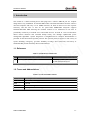
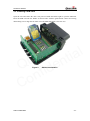
GV500 User Manual
GSM/GPRS/GPS Tracker
GV500
User Manual
TRACGV500UM001
Revision: 1.01
[email protected]
GV500 User Manual
Document Title
GV500 User manual
Version
1.01
Date
2014-03-19
Status
Release
Document Control ID
TRACGV500UM001
General Notes
Queclink offers this information as a service to its customers, to support application and
engineering efforts that use the products designed by Queclink. The information provided is based
upon requirements specifically provided to Queclink by the customers. Queclink has not
undertaken any independent search for additional relevant information, including any information
that may be in the customer’s possession. Furthermore, system validation of this product designed
by Queclink within a larger electronic system remains the responsibility of the customer or the
customer’s system integrator. All specifications supplied herein are subject to change.
k
n
i
l
l
c
a
i
e
t
u
n
Q fide
n
o
C
Copyright
This document contains proprietary technical information which is the property of Queclink
Limited., copying of this document and giving it to others and the using or communication of the
contents thereof, are forbidden without express authority. Offenders are liable to the payment of
damages. All rights reserved in the event of grant of a patent or the registration of a utility model
or design. All specification supplied herein are subject to change without notice at any time.
Copyright © Shanghai Queclink Wireless Solutions Co., Ltd. 2013
TRACGV500UM001
-1-
GV500 User Manual
Contents
Contents ............................................................................................................................................ 2
Table Index........................................................................................................................................ 3
Figure Index ...................................................................................................................................... 4
0. Revision history ............................................................................................................................ 5
1. Introduction ................................................................................................................................... 6
1.1. Reference............................................................................................................................. 6
1.2. Terms and Abbreviations .................................................................................................... 6
2. Product Overview ......................................................................................................................... 7
2.1. Description .......................................................................................................................... 7
2.2. Parts List.............................................................................................................................. 7
2.3. Interface Definition ............................................................................................................. 8
3. Getting Started .............................................................................................................................. 9
3.1. Opening the Case ................................................................................................................ 9
3.2. Closing the Case ................................................................................................................ 11
3.3. Installing a SIM Card ........................................................................................................ 12
3.4. Installing the Internal Backup Battery............................................................................... 13
3.5. Device Status LED ............................................................................................................ 13
4. OBD II-related features ............................................................................................................... 15
4.1. Communication Protocols ................................................................................................. 15
4.2. OBD II Parameters ............................................................................................................ 15
k
n
i
l
l
c
a
i
e
t
u
n
Q fide
n
o
C
TRACGV500UM001
-2-
GV500 User Manual
Table Index
TABLE 1: GV500 PROTOCOL REFERENCE ....................................................................................... 6
TABLE 2: TERMS AND ABBREVIATIONS ......................................................................................... 6
TABLE 3: PART LIST ............................................................................................................................. 7
TABLE 4: DESCRIPTION OF OBD II CONNECTIONS ...................................................................... 8
TABLE 5: DEFINITION OF DEVICE STATUS AND LED ................................................................. 14
TABLE 6: COMMUNICATION PROTOCOLS LIST ........................................................................... 15
k
n
i
l
l
c
a
i
e
t
u
n
Q fide
n
o
C
TRACGV500UM001
-3-
GV500 User Manual
Figure Index
FIGURE 1.
APPEARANCE OF GV500 ............................................................................................ 7
FIGURE 2.
THE OBD II CONNECTOR ON THE GV500 ............................................................... 8
FIGURE 3.
OPENING THE CASE .................................................................................................. 10
FIGURE 4.
CLOSING THE CASE .................................................................................................. 11
FIGURE 5.
SIM CARD INSTALLATION....................................................................................... 12
FIGURE 6.
BACKUP BATTERY INSTALLATION ....................................................................... 13
FIGURE 7.
GV500 LED ON THE CASE ........................................................................................ 13
k
n
i
l
l
c
a
i
e
t
u
n
Q fide
n
o
C
TRACGV500UM001
-4-
GV500 User Manual
0. Revision history
Revision
Date
Author
Description of change
1.00
2013-8-16
Leo LEI
Initial
1.01
2014-03-19
Cid Xu
Updated Introduction information;
Updated the pictures;
Updated 4.2 OBD II Parameters
k
n
i
l
l
c
a
i
e
t
u
n
Q fide
n
o
C
TRACGV500UM001
-5-
GV500 User Manual
1. Introduction
The GV500 is a vehicle tracking device that plugs into a vehicle's OBD II port. It's compact
design allows easy installation. Its internal OBD reader can obtain information from the vehicle's
on-board computer and relay it over GPRS networks. Its built in GPS receiver has superior
sensitivity and fast time to first fix. Its quad band GPRS/GSM subsystem supports
850/900/1800/1900 MHz allowing the GV500's location to be monitored in real time or
periodically tracked by a backend server and mobile devices. Its built in 3-axis accelerometer
allows motion detection and extended backup battery life through sophisticated power
management algorithms. System integration is straightforward as complete documentation is
provided for the full featured @Track protocol. The @Track protocol supports a wide variety of
reports including; emergency, geo-fence boundary crossings, driver behaviour, low battery or
scheduled GPS position and many other useful functions.
k
n
i
l
l
c
a
i
e
t
u
n
Q fide
n
o
C
1.1. Reference
Table 1: GV500 Protocol Reference
SN
Document name
Remark
[1]
GV500 @Track Air Interface Protocol
The air protocol interface between
GV500 and backend server.
1.2. Terms and Abbreviations
Table 2: Terms and Abbreviations
Abbreviation
Description
PWR
External Power Supply
GND
OBD
SAE
Ground
On-Board Diagnostics
Society of Automotive Engineers
TRACGV500UM001
-6-
GV500 User Manual
2. Product Overview
2.1. Description
GV500 is based on the OBD II interface GPS vehicle tracking device, compact design and easy to
install. GV500 contains an OBD II connector which complies with J1962 standard, a 10PIN USB
connector, an internal GSM antenna, an internal GPS antenna and three LEDs.
k
n
i
l
l
c
a
i
e
t
u
n
Q fide
n
o
C
Figure 1.
Appearance of GV500
2.2. Parts List
Table 3: Part List
Name
GV500 Locator
Picture
48mm*25mm*48mm
DATA_CABLE_M (Optional)
TRACGV500UM001
-7-
GV500 User Manual
2.3. Interface Definition
The GV500 has an OBD II connector. It contains power supply and interfaces of CAN bus, K-line,
L-line and J1850 bus. The sequence and definition of the OBD II connector are shown in
following figure:
k
n
i
l
l
c
a
i
e
t
u
n
Q fide
n
o
C
Figure 2.
The OBD II connector on the GV500
Table 4: Description of OBD II Connections
Index
1
2
3
4
5
6
7
8
9
Description
Comment
PWR
External DC power input, 8-32V
L-line
L line of ISO 9141-2 and ISO 14230-4
CAN-L
CAN-L line of ISO 15765-4
J1850-
Bus negative line of SAE J1850
K-line
K line of ISO 9141-2 and ISO 14230-4
CAN-H
CAN-H line of ISO 15765-4
GND
Power and digital ground
GND
Power and digital ground
J1850+
Bus positive line of SAE J1850
TRACGV500UM001
-8-
GV500 User Manual
3. Getting Started
3.1. Opening the Case
Insert the triangular-pry-opener into the gap of the case as shown below, push the opener up until
the case unsnapped.
k
n
i
l
l
c
a
i
e
t
u
n
Q fide
n
o
C
TRACGV500UM001
-9-
GV500 User Manual
k
n
i
l
l
c
a
i
e
t
u
n
Q fide
n
o
C
Figure 3.
TRACGV500UM001
Opening the Case
- 10 -
GV500 User Manual
3.2. Closing the Case
The battery is glued to top cover, so before closing the case you should let the battery connector
plugged in. The step of closing case is shown as following:
k
n
i
l
l
c
a
i
e
t
u
n
Q fide
n
o
C
Figure 4.
TRACGV500UM001
Closing the Case
- 11 -
GV500 User Manual
3.3. Installing a SIM Card
Open the case and ensure the unit is not powered. Slide the holder right to open the SIM card.
Insert the SIM card into the holder as shown below with the gold-colored contact area facing
down taking care to align the cut mark. Close the SIM card holder. Close the case.
k
n
i
l
l
c
a
i
e
t
u
n
Q fide
n
o
C
Figure 5.
TRACGV500UM001
SIM Card Installation
- 12 -
GV500 User Manual
3.4. Installing the Internal Backup Battery
k
n
i
l
l
c
a
i
e
t
u
n
Q fide
n
o
C
Figure 6.
Backup Battery Installation
There is an internal backup Li-ion battery.
3.5. Device Status LED
Figure 7.
TRACGV500UM001
GV500 LED on the Case
- 13 -
GV500 User Manual
Table 5: Definition of Device status and LED
LED
Device status
LED status
CEL
(note1)
Device is searching GSM network
Fast flashing
(Note3)
Device has registered to GSM network.
Slow flashing
(Note4)
SIM card needs pin code to unlock.
ON
GPS chip is powered off
OFF
GPS sends no data or data format error.
Slow flashing
GPS chip is searching GPS info.
Fast flashing
GPS
(note 2)
k
n
i
l
l
c
a
i
e
t
u
n
Q fide
n
o
C
OBD
(note 2)
GPS chip has gotten GPS info.
ON
No external power and internal battery voltage is lower
than 3.46V. GV500 is power off.
OFF
No external power and internal battery voltage is
below 3.55V
Slow flashing
External power in and internal battery is charging
Fast flashing
External power in and internal battery is fully charged
ON
Note:
1 - CEL LED cannot be configured.
2 - GPS LED and OBD LED can be configured to turn off after a period of time using the
configuration tool
3 - Fast flashing is about 60ms ON/ 780ms OFF
4 - Slow flashing is about 60ms ON/ 1940ms OFF
TRACGV500UM001
- 14 -
GV500 User Manual
4. OBD II-related features
4.1. Communication Protocols
GV500 could monitor the OBD II system via not only communication protocols which defined by
SAE but also some special protocols. The list of protocols is shown as follow:
Table 6: Communication Protocols List
No.
1
2
3
4
5
6
7
8
9
10
11
12
13
Protocol
Comment
k
n
i
l
l
c
a
i
e
t
u
n
Q fide
n
o
C
J1850 PWM
41.6kb/s FORD
J1850 VPW
10.4kb/s GM/Chrysler
ISO 9141-2
5 Baud init automatic baud rate
ISO 14230
5 Baud init 10.4kb/s
ISO 14230
Fast init 10.4kb/s
ISO 15765
ID 11bits 500kb
ISO 15765
ID 29bits 500kb
ISO 15765
ID 11bits 250kb
ISO 15765
ID 29bits 250kb
J1939
ID 29bit 250kb
CAN_USER1
11*bits 125*kb
CAN_USER2
11*bits 50*kb
VW TP2.0
Volkswagen CAN protocol
4.2. OBD II Parameters
GV500 can read the following parameters through OBD II system.
1) Vehicle identification number (VIN):
2) OBD Power Voltage
3) Parameter identification (PID)
4) Revolutions per minute of the engine (RPM)
5) Vehicle speed
6) Engine Coolant Temperature
7) Fuel Consumption
8) Distance Statistics
9) Malfunction Indicator Lamp (MIL)
10) Diagnostic Trouble Codes (DTC)
11) Throttle Position
12) Engine Load
13) Fuel Level Input
TRACGV500UM001
- 15 -
GV500 User Manual
Note:
1 - The VIN is the unique identifier of Vehicle. Please note that not all Vehicle support getting the
VIN from OBD II system, because the Vehicle manufacturers are responsible for defining the data
return from OBD II system.
2 - Distance Statistics: GV500 could get the distance in two cases: distance accumulated since
MIL is activated and distance accumulated since DTCs were cleared.
k
n
i
l
l
c
a
i
e
t
u
n
Q fide
n
o
C
TRACGV500UM001
- 16 -