1
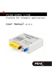
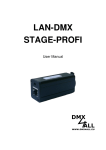
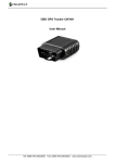
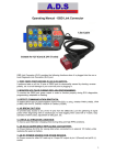
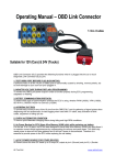
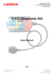
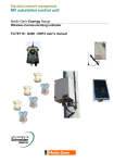
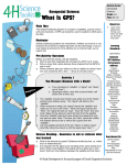
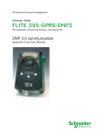
WIFI OBD GPS Tracker T356 User Manual Version:1.000 http://www.ulbotech.com [email protected] T356 User Manual Document Title Version Date Status T356 User Manual 1.000 2015-04-02 Release General Notes Ulbotech offers this information as a service to its customers, to support application and engineering efforts that use the products designed by Ulbotech. The information provided is based upon requirements specifically provided to Ulbotech by the customers. Ulbotech has not undertaken any independent search for additional relevant information, including any information that may be in the customer’s possession. Furthermore, system validation of this product designed by Ulbotech within a larger electronic system remains the responsibility of the customer or the customer’s system integrator. All specifications supplied herein are subject to change. Copyright This document contains proprietary technical information which is the property of Ulbotech copying of this document and giving it to others and the using or communication of the contents thereof, are forbidden without express authority. Offenders are liable to the payment of damages. All rights reserved in the event of grant of a patent or the registration of a utility model or design. All specification supplied herein are subject to change without notice at any time. Copyright © Ulbotech 2015 ---2--- T356 User Manual Contents 0.Revision History.............................................................................................4 1.Introduction ..................................................................................................5 2.Product Overview ..........................................................................................6 3.Getting Started ............................................................................................ 10 4.Installation USB Driver ................................................................................. 12 5.Initiation Device .......................................................................................... 12 6.Connect with Immobilizer ............................................................................. 18 7.Installation Device ....................................................................................... 19 8.Common Problems ...................................................................................... 20 ---3--- T356 User Manual 0.Revision History Revision 1.000 Date 2015-04-02 Author David Lin ---4--- Description of change Initial T356 User Manual 1.Introduction T356 is a WIFI, 0 use-cost OBD II GPS tracking device. It's the built-in high capacity flash for two weeks data storage. The built-in WIFI functionality supports the device to synchronized the all full storage data to the server within quite a short time. T356 can be preset more than 1600 WIFI AP information to support the device sending the data to the server more easy and quickly. Just like during the vehicle refueling, the device could be upload the data to the server via the preset AP. The internal GPS and OBD functions support to real-time recording and analyzing GPS and OBD data, including mileage and fuel consumption data statistics. It's integrated the 3-axis accelerometer can be real-time monitored 8 kinds of bad driving behavior. It's built a power-cut output and a configurable input circuit to facilitate the device's extension functionality. 1.1 Reference document Index 1 2 3 4 5 Document Name Ulbotech Tracking Device Communication Protocol Tracking Device VCP driver installation user manual Tracking Device Configuration Software manual OBD tracking device immobilizer installation user guide Tracking Device File Import & Export Software manual ---5--- T356 User Manual 2.Product Overview 2.1 Description T356 is based on the OBD II interface GPS vehicle tracking device, compact design and easy to install. T356 contains an OBD II connector which complies with J1962 standard. It comprises a micro USB connector, a built-in WIFI antenna, an internal Bluetooth low energy antenna, an internal GPS antenna, an immobilizer output, a multi-functions input and 4pcs LEDs . 2.2 Features OBD connectivity, simple to install, easy to use. Supports all OBDII protocols and SAE J1939(250/500kbaud). Build in WIFI support 802.11 b/g/n. U-blox 6M GPS module with A-GPS. Internal WIFI/GPS/BLE antenna. Internal Immobilizer for anti-theft. Internal multi-functions input. Optional micro-SD holder, Supports up to 4G memory card. Optional Bluetooth low energy(BLE) functions. Internal 3-axis accelerometer. 8 types driver behavior detect. Build in buzzer for alert. Tracking by time, distance, course and status. Geo-fence(Circle, Rectangular and Polygon). FOTA(Firmware updating via WIFI). Supports WIFI SSID list file. ---6--- T356 User Manual 2.3 Parts list Name Picture T356 Micro USB Cable OBDII Extended Cable(Optional) Engine Cut Relay(Optional) Engine Cut and input Pin wire (Optional) ---7--- T356 User Manual 2.4 Interface Definition The T356 has an OBD II connector. It contains power supply and interfaces of CAN bus, K-line, L-line, J1850 bus, multi-function input and immobilizer. The sequence and definition of the OBD II connector are shown in following figure: 9 10 11 12 13 14 15 16 1 2 3 4 5 6 7 8 Description of OBD II Connections: PIN 1 2 3 4 5 6 7 8 Description Not connect Bus positive line of SAE J1850 Not connect Ground Ground CAN_H line of ISO 15765-4 K line of ISO 9141-2 and ISO 14230-4 Not connect PIN 9 10 11 12 13 14 15 16 ---8--- Description Not connect Bus negative line of SAE J1850 Not connect Engine cut line(Optional) Multi-functions input line(Optional) CAN_L line of ISO 15765-4 L line of ISO 9141-2 and ISO 14230-4 External DC power input, 8-32V T356 User Manual 2.5 Function Interface Definition 1 2 3 7 4 5 8 6 Descriptionoffunction: Index 1 2 3 4 5 6 7 8 Description Micro SD card holder OBD status indicator LED(Orange) GPS status indicator LED(Green) WIFI status indicator LED(Red) Bluetooth status indicator LED(Blue or White) GPS antenna(25mm*25mm) Buzzer Micro USB port DefinitionofDevicestatusLED: LED WIFI (Red) GPS (Green) OBD (Orange) Bluetooth (White) Device Status Module power off Searching WIFI AP Connected WIFI AP Connected to server Sending data Module power off Searching GPS info 2D fixed 3D fixed OBD unconnected OBD connected OFF Always ON ---9--- LED Display 100ms ON, 6s OFF 1s ON, 1s OFF 500ms ON, 500ms OFF 100ms ON, 100ms OFF Always ON 100ms ON, 6s OFF 1s ON, 1s OFF 500ms ON, 500ms OFF 100ms ON, 100ms OFF OFF Flashing Power off Connected T356 User Manual 3.Getting Started 3.1 Preparation The device with the default built-in 16Mb Flash to store the data, user also can use Micro-SD card to expand the storage space of the device. If user does not need the expanded Micro-SD card, please refer to 3.5 section. For Micro-SD card installation (Please choose this function firstly) The Micro-SD card should be not more than 4G, and ensure the data of this card have been copied. Because the original data of the card will be covered and cannot be recovered when the device is working. 3.2 Opening the Case First loosen these two nuts on the cover by cross screwdriver as below picture showed: Lift the upper cover near the end of the OBDII interface, from the fixed slot: ---10--- T356 User Manual Slide out the upper cover and removed it: 3.3 Insert Micro SD card Insert the Micro SD card as below picture showed: 3.4 Closing the Case According to the inverse order of the opening cover to close the upper cover, after fix the case by nuts. ---11--- T356 User Manual 4.Installation USB Driver Details refer to document of “Tracking Device VCP driver installation user manual”. 5.Initiation Device Initialization device can be set with matching configuration software. Please refer to the document “Tracking Device Configuration Software manual” to login device by configuration software mode; refer to the document ”Ulbotech Tracking Device Communication Protocol” to login device via text messages mode. 5.1 Web Server Setting 5.1.1 Web server address, port and protocol setting Login device via configuration software, select “Service” option as below showed: Entry server address or IP, Port, using TCP/UDP protocol and acknowledgement in “GPRS Server Host”: Click “Write” button. 5.1.2 Web server upload cycle and format setting Login device via configuration software, select “Service” option as below showed: Edit setting GPRS server upload mode as below showed: Click “Write” button. 5.2 WIFI Setting 5.2.1 WIFI module enable setting Login device via configuration software, select “WIFI” option as below showed: ---12--- T356 User Manual Select WIFI module working mode: WIFI disable: WIFI module will be off status. WIFI STA: Opened “WIFI station” function, now module is seeking WIFI AP automatically and connect to configured WIFI to upload device data. WIFI STA+AP: dose Opened “WIFI station” and “soft-AP” function, station function will searching WIFI AP automatically and connect to configured WIFI to upload device data. And “soft-AP” function will provide an AP to the mobile equipments and the device to build connection and communication. Click “Write” button. 5.2.2 WIFI AP SSID and password setting Set soft-AP function’s SSID and password Login device via configuration software, select “WIFI” option as below showed: Input SSID and password Click “Write” button. 5.2.3 WIFI access point(AP) list setting The device supports 16 separate AP setting, also supports to configure more AP through the imported AP file ,the AP file supports max 32K bytes, both can work simultaneously or independently. Setting 16 independent AP: Login device via configuration software, select “WIFI” option as below showed: Edit AP “SSID” and “password”: ---13--- T356 User Manual Click “Write” button to finish setting. Import AP file: By using File Import & Export software to connect and login the device: Click ”Import” button, select the AP file for configuration: ---14--- T356 User Manual Click “Open” to import file, file send finished: Click ”OK” and close the software. 5.3 OBD setting 5.3.1 Select OBD protocol The device factory default settings is automatic recognition of all OBDII standard protocol. If user don’t know the protocol of the car, user can select “automatic”, device will identify OBDII protocol from 1 to 9 automatically. When using the J1939 protocol to connect to the truck, the protocol must be set as the J1939 protocol. The J1939 protocol for most of trucks is 250kbaud, in case cannot connect with 250kbaud, user may try to set as 500kbaud setting: ---15--- T356 User Manual Login device via configuration software, select “OBDII” option as below showed: Setting automatic recognition: Setting J1939 29bit, ID 250kbaud: Setting J1939 29bit ID, 500kbaud Click “Write” button to finish setting. 5.3.2 Reading OBD parameters setting Device at most can real-time reading 16 OBDII parameters or J1939 parameters. The default settings of the device is automatic recognition protocol. Reading “Engine Coolant Temperature” (0105), “Engine RPM” (010C), “Vehicle Speed” (010D), “Fuel Level” (012F) and “Distance since diagnostic trouble codes cleared” (0131)” of 5 parameters, can modify or increase the parameters through the “OBP” command. Login device via configuration software, select “OBDII” option as below showed: Edit “Read OBDII/J1939 parameters” setting: The configuration parameters is 16 hexadecimal format, consisting of 2 bit OBDII server code and the following PID. Example: 0105 said that reading 01 serviced the 05 parameter, meaning read Engine Coolant Temperature. Click “Write” button to finish setting. When choosing the J1939 protocol, the parameter are represented in fixed 6 bytes hexadecimal format to corresponding need to read the Parameter Group Number(PGN).If the length is less than 6 bytes, need to insert “0” on the front. ---16--- T356 User Manual Edit “Read OBDII/J1939 parameters” setting: Example: 00FEF1 said that reading PGN 65265 “Cruise Control/Vehicle Speed” parameter. Click “Write” button to finish setting. 5.3.3 OBD parameters alarm setting When OBD II protocol setting as J1939, device disable this function. The device supports “Diagnostic Trouble Code (DTC) “alarm and 4 sorts of userdefined alarm parameter setting. Configuration parameters included the reading OBDII parameter, the judgment condition, monitoring value and duration of four parameters. If the temperature of configuration of “Engine Coolant Temperature” exceeded 105 degrees Celsius for 60 seconds, or configure “Fuel Level” less than 10% lasted for more than 30 minutes, the device will alarm: Login device via configuration software, select “OBDII” option as below showed: Setting “OBDII Alarm” parameters: Click “Write” button to finish setting. 5.4 Power Save Setting 5.4.1 Power Save Setting User, SMS server and Web server upload cycle just will upload data and message via setting parameters of “short interval” under the normal working mode of the device. When the device under power save mode, the device will ---17--- T356 User Manual use the configuration parameter of “Long interval “cycle upload message and data. Therefore, the device will be in off status when it does not need to upload data for a long time and it’ll achieve power saving function. The device will be automatic wake-up to upload data if it’s needed. The device will be in the power-saving status according to the configured condition of power save status. Login device via configuration software, select “Service” option as below showed: Selected “device upload cycle” switch to “long interval” status. Click “Write” button to finish setting. 5.4.2 Power Down Setting To further economize power and protect the car battery, can set device to be in off status when achieve the condition of the configuration. When the condition of the shutdown is removed, device will automatically exit the off status. Login device via configuration software, select “Function” option as below showed: Setting the battery low voltage threshold value of vehicle detection: Click “Write” button, Select “Service” option as below showed: Selected the condition of device in off status and delay time: Click “Write” button to finish setting. 6.Connect with Immobilizer Details refer to document of “OBD tracking device immobilizer installation user guide” ---18--- T356 User Manual 7.Installation Device To find the OBD port on the car to insert the device. Most of the OBD port located in the driver side and under of the dashboard or near the walking box as above picture showed. ---19--- T356 User Manual 8.Common Problems 8.1 Device connected with car but no working. Check the OBDII interface of car if has power output and with sufficient voltage. Check if device connected with Car OBD II port stability. Check if the device in “Power down” status caused by “Power down” parameter of the device set error. 8.2 GPS cannot positioning Check if the device at a good GPS signal area. Check opened AGPS function and GPSR or WIFI enable to connect with Internet. Check GPS module is in power save status. Using OBDII extended cable to move device to a good GPS signal area and keep the GPS antenna upward. 8.3 OBD cannot connect Check if car support OBDII standard . Check if OBD function closed. Check if car engine is working, if it’s not, it’ll no OBD signal. 8.4 WIFI cannot connect Check if WIFI function closed. Check if configured WIFI AP list and the device is in one or more signal coverage in the AP list, and the password correct. Check if device is in “Power down” status. ---20---