1
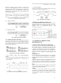
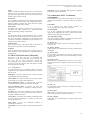
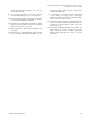
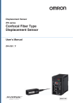
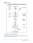
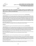
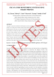
International Journal of Computer Applications (0975 – 8887) Volume 121 – No.13, July 2015 An Introduction to Functional Verification of I2C Protocol using UVM Deepa Kaith Janakkumar B. Patel, PhD Neeraj Gupta Student, M.Tech Professor Assistant Professor ECE Dept., ASET Amity University Haryana ECE Dept., ASET Amity University Haryana ECE Dept., ASET Amity University Haryana ABSTRACT The fabrication technology advancements lead to place more logic on a silicon die which makes verification more challenging task than ever. The large number of resources is required because more than 70% of the design cycle is used for verification. Universal Verification Methodology was developed to provide a well structured and reusable verification environment which does not interfere with the device under test (DUT). This paper contrasts the reusability of I2C using UVM and introduces how the verification environment is constructed and test cases are implemented for this protocol. Keywords Inter Integrated circuit, Verification environment, Universal Verification Methodology, intellectual property, DUT 1. INTRODUCTION Serial bus requires fewer IC pins, and the less wiring andless number of traces on printed circuit boards than parallel bus. Many common embedded system peripherals support serial interfaces. Using I2C, processors do not require shared memory to communicate. I2C called as inter integrated circuit is a simple, lowbandwidth, short-distance protocol [2]. It was made by Philips Semiconductors in the early 1980s reduce the manufacturing costs of electronic products. The I2C allows 7-bit or 10 bit addressing with two bi-directional lines: serial clock (SCL) and serial data (SDA) [7]. The pull-up resistors for each line are only added. All the devices on the line can act as either a slave or a master. The clock line can only be drived by the master devices. The transmission of 8-bit of data and 7-bit of address with a control bit is done serially using the interface. It is difficult to verify the functionality of the design using traditional testbenches as the design becomes large. Thus, hardware verification languages are used for designing the modules. More than 70% of the time is spent on verification which also consumes more resources than the design itself [3]. This arise the need for developing modular, reusable and robust environment for verification. The Open Core Protocols (OCP) were introduced for accessing System on Chip functional units along with maintaining high performance. It allows software address communication between the units of Chip. Universal Verification Methodology (UVM) is a methodology for functional verification of design units. It is based on OVM version 2.1.1 and is created by Accellera. Its Class Library provides [6] the building blocks needed to quickly develop well-constructed and reusable verification components and test environments. It uses system Verilog as its language and all the major simulation vendor supports it. UVM is an open source methodology for using System-Verilog. It is designed mainly for verification of intellectual properties and testbench components so that testbenches are reusable and verification code is more portable. Each verification component follows a consistent architecture for simulating, checking and collecting functional coverage. The verification environment developed through System-Verilog may be different depending upon implementer while that built using UVM remains same for different vendors [8]. 2. I2C PROTOCOL I2C provides chip-to-chip serial communications using only two lines in an interface. The two lines in the I2C bus carry one bit of address selection, direction control, and data at a time. The data (SDA) line carries the data, while the Clock (SCL) line synchronizes the sender and receiver during the transfer. Device that uses I2C protocol requires very few pins to perform the same function as their larger parallel interface equivalents. The I2C bus has three modes of operation: standard mode (0 to 100 kbps), fast mode (0 to 400 kbps) and high-speed mode (0 to 3.4 Mbps) [1][11]. Fig 1: Multiple master and slave connection in I2C 2.1 I2C Specifications The I2C bus physically consists of two bidirectional active wires- serial Data line, serial Clock line and a ground connection. Each device connected to the bus has its own unique address and can act as a receiver or a transmitter, depending on the required functionality. The I2C bus is designed as a multi-master bus. The bus Master is the IC that starts a data transfer on the bus and all the other ICs are regarded as Slaves. Master will issue an 'Attention' signal to all of the connected devices known as START. Then the Master sends the ADDRESS of the slave device it wants to access. The Read or Write operation signal bit is also send along with the ADDRESS bits. All the devices connected on the bus will compare the sent address bits with their own address and if it doesn't match, they simply wait till the bus is released and if 10 International Journal of Computer Applications (0975 – 8887) Volume 121 – No.13, July 2015 the address matches; chip will produce a response signal known as Acknowledgement (ACK). On receiving an acknowledgement, master starts transmission of DATA. Each data byte is 8 bits long. An acknowledge bit follows each transferred byte. After transmission is done, the Master will issue the STOP signal [7]. 2.1.5 Data Validity The data on the SDA line are valid for high period of serial clock pulse as shown in the figure below. Fig 2: I2C Communication Frame Format Fig 7: Timings of data validation 2.1.1 Write operation 2.2 Design Architecture of I2C core The system architecture of the I2C shown below has top level module as i2c_master_core and the sub module as i2c_slave, tb_master_module and i2c_master_top. The low level modules are i2c_master_byte_controller and i2c_master_bit_controller. Fig 3: Write operation frame format 2.1.2 Read operation Fig 4: Read operation frame format Fig 8: Design hierarchy of I2C master core 2.1.3 START and STOP conditions All communication begins from a START signal and can be finished by a STOP signal. SCL being High and a high to Low transition on the SDA line depicts a START condition and SCL being High and a low to High transition on the SDA depicts a STOP condition [1]. Fig 5: Start (S) and Stop (P) condition 2.1.4 Transfer Data and acknowledgement format Every byte that is that is transferred using SDA line must be 8 bit long. Each transferred byte is followed by an Acknowledge bit. Fig 6: Data and acknowledgement in I2C protocol 3. UNIVERSAL VERIFICATION METHODOLOGY 3.1 The UVM Verification Components UVM library consists of base classes and infrastructure facilities. Base classes in the UVM hierarchy largely fall into two distinct categories: components and data [8]. The component class hierarchy derived from uvm component is intended to model permanent structures of the testbench like monitors and drivers. Data classes derived from uvm sequence item are intended to model stimulus and transactions. Design Under Test It is the design whose specifications needs to be confirmed. This is basically the RTL description in the designing language. It tells the features and the functions of the design. Sequencer Sequencer is the entity on which the sequences will run. To test DUT behavior, sequence of transaction needs to be applied. Sequencer runs stimulus generation code and sends sequence items down to driver whenever driver demands by it. Driver Driver is used to drive the DUT signals. It receives the sequence items from the sequencer and put on the interface. It is the active part of the environment. Monitor A monitor is the passive element of the verification environment. It scans the DUT signals coming on the interface, assembles information as a packet and then transfers it to coverage collector and scoreboard for coverage information. 11 International Journal of Computer Applications (0975 – 8887) Volume 121 – No.13, July 2015 Agent Agent is an abstract container having a driver, a monitor and a sequencer. It has two modes of operation: passive and active [3]. It drives the signal to the DUT in active mode and scans the DUT signals in passive mode. final phase: It gives information that the phases completed and simulation can be terminated. Scoreboard It is a verification component to check the response from the DUT against the expected response by comparing them to the Reference Model. It informs how many times the response matched and how many times it failed. The architecture of environment developed for I2C protocol verification has different components which are explained below Environment It assembles the structure. It contains one or more agents, scoreboard and other components for measurement and checking depending on design requirements. Test It is the top-level of the component hierarchy. DUT. In UVM tests are the classes that are derived from an uvm_test class. The test class enables configuration of the testbench and verification components to determine the dynamic behavior of the processes by using sequences. Sequence items These are the necessary data objects that are passed at an abstract level between the verification components. Sequences These are gathered from sequence items to build a real set of inputs. Sequences create a randomized or a pre-determined set of transactions. 3.2 The UVM Class Library Hierarchy uvm_object is the base class for all components and sequences in UVM. uvm_component class is derived from this class and all uvm components extends the uvm_component class. Transaction class is derived from uvm_object class and sequence_item and sequence extends the uvm_transaction class [4]. 3.3 Architecture of I2C Verification environment Top module It is a testcase class that contains instances i2c_environment, master_agent and slave_agent. of i2c_environment It is an I2C component that contains master/slave agent. Agent can be configurable for active or passive mode. In this checkers and coverage can be configured. i2c_environment_config This class contains the number of masters and slaves present in the environment that can be configured. i2c_master_seq It encloses the sequences used for verification making test effectively easy. i2c_master_monitor It takes data for score-boarding and coverage collection from the interface. i2c_master_driver Driver connects the sequences by using i2c_sequence_items as a basic item with this class. It provides flexibility to choose the type of test. i2c_master_agent Master agent is configurable either in active or in a passive mode. It contains driver, sequencer and monitor and coverage collector.. 3.2.1 UVM Phases: In UVM simulation runs in predefine phases and all the components in the verification environment will be called in order as below build phase: It forms the basic structure of the environment by instantiating required components. connect phase: It is used to connect ports to exports, exports to ports and ports to ports in child component. end_of_elaboration phase: It indicates that verification environment has been completely tuned and assembled. start_of_simulation phase: It indicates the DUT that verification environment is completely configured and is ready to start. run phase: It is used to run simulation and is divided into several run phases. It is the only phase uses task to define as this phase consumes more time. extract phase: It is used to extract data from different points of the verification environment. It obtains all data from scoreboard and extract it. Fig 9: Verification environment with DUT as a slave i2c_slave_seq It contains the sequences used for verification and makes testcase short and easy. i2c_slave_agent Slave agent is configurable either in active or in a passive mode. It contains driver, sequencer and monitor. i2c_slave_monitor It takes data for score-boarding and coverage collection from the interface. check phase: It verify any unexpected condition in verification environment. report phase: It gives the report of the particular performed test . 12 International Journal of Computer Applications (0975 – 8887) Volume 121 – No.13, July 2015 4.3 Checker and coverage Checkers are used for checking the expected result. Checking is done by monitors and scoreboards and depends on the requirement of the design. Coverage groups give the functional coverage of the tested features. It helps in applying coverpoints. 4.4 UVM verification environment for I2C bus controller Fig 10: Verification environment with DUT as a master 3.3.1 Testcases Test cases for the four working modes of DUT are given below: i. master_tx In this DUT works in a transmit mode as a master. This means slave in the verification environment has to build up in rx mode to receive data send by DUT. The i2c_master_seq generates the data which is sent to the master core through the i2c_master_driver. Serial data which is to be transmitted by the master are given to the master by the i2c_master_driver and it sends the same data to the scoreboard as the packet_1 through UVM mail box. The data received by the slave are fed back to the scoreboard via slave_driver for comparison as packet_2 through the mail box. Then, the sent and received data_item as packet_1 and packet_2 are compared. If it do not match, it will produce an uvm_error. ii. master_rx In this DUT works in a receive mode as a master. This means slave in the verification environment has to build up in tx mode to transmit data to DUT. iii. slave_tx In this DUT works in a transmit mode as a slave. This means master in the verification environment has to build up it in rx mode to receive data send by DUT. iv. slave_rx In this DUT works in a receive mode as a slave. This means master in the verification environment has to build up it in tx mode to transmit data to DUT. 4. THE VERIFICATION PLAN The Verification Plan defines exactly what needs to be tested, and drives the coverage criteria [9]. Feature extraction, Stimulus generation plan, Checker plan and Coverage plan are the important parts of a verification plan. 4.1 Feature Extraction It contains the list of all the features to be verified. For the I2C as a DUT features to be extracted are given below START and STOP condition generation. ACK and NACK condition generation. The response of the DUT in different states: idle, read, write, address_match, ack. Synchronization of clock between the master and slave. Validation of 7-Bit address. Direction of data transfer by checking R/W bit. Generate all possible data transfer formats of connected devices. 4.2 Stimulus Generation The type of the data transfer i.e. write or read. The length of the data transfer. The speed of the data transfer. The ACK/NACK generation. Clock stretching in slave. Arbitration occurrence. Clock frequency of each connected device. The addresses of the slaves and those send by the master. Fig 11: UVM verification environment for I2C protocol 5. CONCLUSION AND SCOPE In this paper UVM is used to build a verification environment which is reusable to verify any I2C as a DUT. UVM provides built-in reflection and has additional macros and functions capabilities. It also provides a rich set of base class library for efficient verification. A detailed verification plan for analyzing the results and creating proper stimulus is required for the functional coverage. This might seem to be time consuming but requires less effort than other similar tests. UVM if properly framed provides a fault free design by covering all the necessary and corner test cases. The test environment is interoperable and can be implemented in real time systems. 6. REFERENCES [1] Philips Semiconductor, version 2.1 January 2000. I2C-bus specification and user manual. [2] F.Leens, February 2009. An Introduction to I2C and SPI Protocols, IEEE Instrumentation & Measurement Magazine, pp. 8-13, [3] Mulani P., Patoliya J., Patel H., Chauhan D., “Verification of I2C DUT using SystemVerilog”, International Journal 13 International Journal of Computer Applications (0975 – 8887) Volume 121 – No.13, July 2015 of Advanced Engineering Technology, Vol. 1, No. 3, pp 130-134, Oct.-Dec 2010. Verification. ISBN: 978-987-1907-86-1 IEEE Catalog Number CFP1454E-CDR. [4] An Accellera Organization, June 2011. Universal Verification Methodology (UVM) 1.1 Class Reference. [9] T Tarun Kumar, CY Gopinath, June 2014. Verification of I2C Master Core using System Verilog-UVM International Journal of Science and Research (IJSR), ISSN - 2319-7064, Volume 3 Issue 6. [5] Glasser M., February 4, 2011. UVM: The Next Generation in Verification Methodology, Methodology Architect, Courtesy of Mentor Graphics Corporation. [6] Young-Nam Yun, Jae-Beom Kim, Nam-Do Kim, Byeong Min, 2011. Beyond UVM for practical Soc Verification, IEEE- 978-1-4577-0711-7, pp 158-162. [7] NXP Semiconductors, 2012. I2C-bus specification and user manual. [8] Juan Francesconi, J. Agustin Rodriguez, Pedro M. Julian, 2014. UVM Based Testbench Architecture for Unit IJCATM : www.ijcaonline.org [10] Alexander W. Rath, Volkan Esen and Wolfgang Ecker, 2014. A Transaction-Oriented UVM-Based Library for Verification of Analog Behavior, IEEE- 978-1-47992816-3, pp 806-811. [11] Deepa Kaith, Janankkumar B.Patel, Neeraj Gupta, “An Implementation of I2C Slave Interface using Verilog HDL”, Internatioal Journal of Modern Engineering Research, ISSN: 2249-6645, Vol.5, Issue 3, pp 55-60, March 2015. 14