1
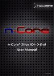
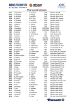
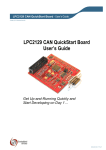
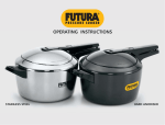
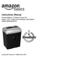
International Conference on Computer Science, Electronics & Electrical Engineering-2015
VEHICLE MONITORING AND
ELECTRONIC STABILITY
PROGRAM USING ARM
Vasudeva
M.Tech (Digital Electronics)
VTU Extension Centre
UTL Technologies Ltd. Bangalore
Dr. P Venkataratnam
Principal
VTU Extension Centre
UTL Technologies Ltd. Bangalore
ABSTRACT
The present generation vehicles are much more intelligent than they were years back because modern engines
are controlled by electronically using ECU. This paper presents the implementation of CAN protocol using
ARM7 processor for monitoring of vehicle and ESP for Electronic safety of the vehicle. The main features of
the system includes monitoring of Gas level, Engine temperature level, driver monitoring to avoid accidents,
such as eye blink monitoring, alcohol monitoring through Control Area Network (CAN) which is a Serial bus
standard for automotive application with low cost and reduction wiring complexity. The other important
feature of the paper is Electronic Stability Programming (ESP) for the vehicle stability to avoid single vehicle
crashes and collision due to the over-steering and under-steering problems. The software part is done in keil
using embedded C.
Keywords— Controller Area Network (CAN), ARM, ESP, Keil, Embedded C,
I. INTRODUCTION
Controller Area Network (CAN) is a bus mainly for automobile which is a shared serial bus
communication protocol, Robert Bosch originally developed CAN in 1986 .The distributed control systems in
cars are increasing which increases wiring costs of car body electronics led to the birth of the Automotive Serial
―Controller Area Network" protocol. Although initially it was deve loped for the use of the automotive industry,
its use quickly spread to a wide variety of applications in embedded systems like industrial automation
wherever the high speed communication is required. With growing acceptance in various industries not
necessarily r elated to the automotive industry, hence the protocol name was renamed as Controller Area
Network (CAN).
The ESP is the electronic stability program is an active safety technology that helps to prevent
accidents by assisting the driver in case of the loss of control of the vehicle. ESP is especially effective in
keeping the vehicle on the road and controlling rollover accidents which is single car crashes account for over
1/3 of all in vehicle accidents. The loss of control on vehic le is having two major problems i.e. under steering
and over steering. The over steer problem causes spin out where as under steer causes plow- out. ESP can
effectively reduce this problem by using stability program using ARM.
II. BLOCK DIAGRAM
Vehicle monitoring and ESP using ARM is a system of sensors and CAN protocol to monitor the
various parameters of the vehicle, and the ESP is the Electronic stability program which is for the safety of the
vehicle.
The vehicle monitoring and control system monitors the various parameters of the vehicle such as
Gas, Humidity, Alcohol and Eye blink. The sensors used for ESC have to send data at all times in order to
detect possible defects as soon as possibl e. They have to be resistant to possible forms of interference (rain,
obstacle, holes in the road, etc.).
The ESP is the electronic stability program is an active safety technology that helps to prevent
accidents by assisting the driver in case of the loss of control of the vehicle. ESP is especially effective in
68
©2015 ISRASE
ISRASEeXplore Digital Library
International Conference on Computer Science, Electronics & Electrical Engineering-2015
keeping the vehicle on the road and controlling rollover accidents which is single car crashes account for over
1/3 of all in vehicle accidents.
The loss of control on Vehicle is having two major problems i.e. under steering and over steering the
over steer problem causes spin out where as under steer causes plow-out. ESP can effectively reduce this
problem by using stability program using ARM
Fig 1; Block Diagram of Vehicle monitoring and ESP using ARM
2.1 ARM
The ARM LPC2129 is a 16/32 bit ARM7TDMI-S CPU with 128/256 kilobytes of high speed flash
memory. A 128-bit wide internal memory interface and enable 16/32-bit code execution at maximum clock
rate. For critical code size applications, the alternative 16-bit Thumb Mode, which reduces code by more than
30% with minimal performance penalty. With their compact 64 and 144 pin packages, low power consumption,
it contains various 32-bit timers, combination of 4 channel 10-bit ADC and 2/4 advanced CAN channels or 8channel 10-bit ADC and 2/4 advanced CAN channels (64 and 144 pin packages respectively), and up to 9
external interrupt pins these microcontrollers are particularly suitable for industrial control, medical systems,
access control and p oint-of-sale. Number of available GPIOs goes up to 46 in 64 pin package. In 144 pin
packages number of available GPIOs tops 76 (with external memory in use) through 112 (single-chip
application). It operates on dual power supply. The CPU operating voltage range of 1.65V to
1.95V (1.8V +/- 8.3%). The I/O power supply range of 3.0V to 3.6V (3.3V +/- 10%).
2.2 Temperature/Humidity sensor
The Temperature/Humidity sensor helps to determine the amount of water vapor present in the air.
When the rainfall begins, the wiper should start functioning automatically and wipe out the water present in
the windshield. In this existing system the windshield should function based on the intensity of rainfall. The
rain can be classified on its intensity as drizzling, low rainfall, heavy rainfall. Based on the intensity of rain the
wiper motor speed is adjusted. The humidity sensor used here is SHT25..The humidity range that it can able
to detect is 0 to 100% RH (Relative Humidity). It operates at the temperature of -40 ºC to +125 ºC.
2.3 EYE BLINK SENSOR
This sensor P2700 is a IR sensor which measures and controls the eye blink with the help of IR. The IR transmitter
transmits the rays of infrared to our eye. The receiver side is IR that can receive the reflected rays of
infrared from eye. If the eye is closed means IR receiver output will be high otherwise the output of IR
recover is low. This gives the information of the eye position whether the eye is closing or opening. This output is
given to indicate the alarm or display circuit. This involves controlling the accident due to unconscious through Eye blink.
The goal of this is to develop a system to avoid collision and the vehicle secure. Protect it by the occupation of
the intruders. It is difficult to take care of ours while in running by less conscious. If we done all the vehicles
with automated security system that provides high security to driver, also gives alarm.
69
©2015 ISRASE
ISRASEeXplore Digital Library
International Conference on Computer Science, Electronics & Electrical Engineering-2015
2.4 ALCHOHOL/GAS/SMOKE SENSOR
The Alcohol sensor is using here is the MQ2 which is able to detect the alcohol content by person
which is connected to the controller and monitors the driver weather he is drunk or not and gives information
to the microcontroller through CAN contro l area network and which will be displays on LCD and gives
warning light and buzzer if driver is careless then it will switch off the ig nition system by relay. In current
technology scenario, monitoring of gases produced is very important. From home appliances such as air
conditioners to electric chimneys and safety systems at industries monitoring of gases is very crucial. Gas
sensors are very important part of such systems. The working principle of gas sensor is, when a gas
interacts with this sensor, it is first ionized into its constituents and is then adsorbed by the sensing element.
This adsorption creates a potential difference on the element which is conveyed to the processor unit through
output pins in form of current. The gas sensor used here is MQ -2. It is sensitive to carbon monoxide, LPG,
butane, propane etc.
2.5 PIR
The PIR (Passive Infra-Red) Sensor is a device that detects motion by measuring changes in the
infrared levels emitted by surrounding objects. This motion can be detected by checking for a high signal on a
single I/O pin. PIR sensor, have elements made of a crystalline material that generates an electric charge when
exposed to infrared radiation. The changes in the amount of infrared raking the element change the voltages
generated, which are measured by an on-board amplifier. The device contains a special filter called a Fresnel
lens, which focuses the infrared signals onto the element. As the ambient infrared signals change rapidly, t he
on- board amplifier trips the output to indicate motion.
2.6 LCD
LCD consists of two glass panels, with the liquid crystal material sand witched in between them. The
inner surface of the glass plates are coated with transparent electrodes which define the character, symbols or
patterns to be displayed polymeric layers are present in between the electrodes and the liquid crystal, which
makes the liquid crystal molecules to maintain a defined orientation angle.
III. INTRODUCTION TO COMMUNICATION PROTOCOLS
The generation is increasingly Internet connected and networked environment. The various
communication protocols are developed to reach this goal .The design of the protocol are based on the
applications and differ from one another. In particular, as per industry standard the protocols are of ―higher end‖
and the ―lower end‖ protocols. The protocols like factory bus, address the overall factory system information
protocols are called as the higher end protocols, while the fieldbus, address the inter processor communication
as well as the sensor/actuator communication protocols are lower end protocols
Table 1: Comparative case study of different protocols
3.1 CAN OVERVIEW
Controller Area Network (CAN) is a bus mainly for automobile which is a shared serial bus communication
protocol, Robert Bosch originally developed CAN in 1986 .The distributed control systems in cars are
increasing which increases wiring costs of car body electronics led to the birth of the Automotive Serial
―Controller Area Network" protocol. Although initially it was developed for the use of the automotive industry,
its use quickly spread to a wide variety of applications in embedded systems like industrial automation
wherever the high speed communication is required. With growing acceptance in various industries not
necessarily r elated to the automotive industry, hence the protocol name was renamed as Controller Area
70
©2015 ISRASE
ISRASEeXplore Digital Library
International Conference on Computer Science, Electronics & Electrical Engineering-2015
Network (CAN). CAN uses a serial bus network to send message. The node connection is every node
connected to every other node in the serial network, the need for a central controller for the entire network is
made redundant. A block diagram of a typical CAN network used for communication is shown in Fig 2.
Fig 2; CAN communication block diagram
3.2 VEHICLE WITHOUT CAN
Fig 3; Vehicle without CAN.
The figure 3 shows the system without CAN (control area network), here the parameter of the vehicles
are arranged randomly which will not have any priorities but as per the vehicle efficient and safety the priority
becomes a important fact or to have the safety. The CAN is a serial Bus which is a communication protocol
mainly made for the automobiles, CAN have the efficient transmission of data from sensors, actuators to the
other devices like controller.
71
©2015 ISRASE
ISRASEeXplore Digital Library
International Conference on Computer Science, Electronics & Electrical Engineering-2015
2.3 VEHICLE WITH CAN
Fig 4. Vehicle with CAN.
The figure 4 shows the arrangement of systems with CAN which is a systematic arrangement for the
efficient vehicle monitoring and controlling and also gives the safety to the vehicle. The CAN control area
network is having two types of CAN in it those are CANH and CANL which are called CAN high and CAN
Low respectively.
The some of the parameters in the figure are should be monitored and controlled effectively before taking
care of other parameters, for example Engine control , ABS (Anti breaking system), Active suspension these
should have higher priority as shown in the figure later we can monitor and control the other parameters like
Air conditioning, Lighting, Power locks, power sea ts etc. This is the actual advantage of the CAN protocol.
The development of CAN began when more and more electronic devices were implemented into modern
motor vehicles. Examples of such devices include engine management systems, active suspension, ABS, gear
control, lighting control, air conditioning, airbags and central locking. All this means more safety and more
comforts for the driver and of course a reduction of fuel consumption and exhaust emissions.
IV. ESP
Electronic Stability programming (ESP) is also referred as electronic stability control which helps
drivers to avoid crashes or collision by reducing the danger of losing vehicle control results In over-steering and
under-steering.. When a driver loses control of their car ESCP becomes active. It uses controlled technology to
apply individual brakes to individual wheels and bring the car safely back on track, without any crashes or
collision.
The research shows that ESP can reduces the risk of:
•
Single car crashes by 27%
•
Single 4WD crashes by 53%
Only ESP active safety device has such potential to reduce single car crashes.
ESP uses a number of intelligent sensors to work efficiently that is capable of detect any loss of control of
vehicle and automatically apply the brake to the relevant wheel and avoids in-steering and over-steering,
ESP is of assistance to the driver in:
•
stabilizing the car.
•
Improving traction on slippery or icy roads.
It’s not all ESP systems are identical. The hardware may remain same, but ESP systems are programmed
is depends upon the manufactures to respond once loss of control is detected. Generally, the effectiveness of
72
©2015 ISRASE
ISRASEeXplore Digital Library
International Conference on Computer Science, Electronics & Electrical Engineering-2015
ESP is dependent upon the amount of traction between the road and the Vehicle. Therefore on a vehicle with
old, worn or inappropriate tires. ESP will be less effective than on a vehicle with new tires or tires with specific
to a road environmental condition. The ESP is the electronic stability program is an active safety technology that
helps to prevent accidents by assisting the driver in case of the loss of control of the vehicle. ESP is especially
effective in keeping the vehicle on the road and controlling rollover accidents which is single car crashes
account for over 1/3 of all in vehicle accidents.
The loss of control on Vehicle is having two major problems i.e. under steering and over steering. The
over steer problem causes spin out where as under steer causes plow-out. ESP can effectively reduces this
problem by using stability program using ARM.
4.1 Over steering
Over steering is the problem occurs when the steering wheel is steered to a certain angle during driving
and the rear tires s lip outward losing traction. It is difficult to control this situation under during cornering and
due to this vehicle can spin be cause of rear wheel loss traction and this causes vehicle speed to increase and
accidents
Fig 5; over steering of vehicle
4.2 Under steering
Generally, vehicles are designed to have under steering. Under steering is the problem occurs when the
driver steers the steering wheel to a certain angle during driving and the front tires get slip toward the reverse
direction of the desired direction. The tires can easily lose the traction in the cornering due to under steering
and results in single car crashes and accidents when the curves gets bigger vehicle tends to slip outward and the
speed increases.
Fig 6; under steering of vehicle
73
©2015 ISRASE
ISRASEeXplore Digital Library
International Conference on Computer Science, Electronics & Electrical Engineering-2015
4.3 ESP controls during over steering
The ESP system is the Electronic stability Programming system which can effectively controls the
problem of over steering, ESP recognizes the directional angle of the vehicle with the steering wheel angle
and the slipping route that occurs towards the vehicle cornering direction during over steering with the ARM
microcontroller. Then the ESP system slowdowns the front wheel to compensate the Vehicle moment value.
This is how ESP helps to the vehicle so that vehicle does not lose its driving direction and the driver can steer
the vehicle as he or she intends to avoid accidents
4.4 ESP controls during under steering
The ESP system recognizes the directional angle of the vehicle with the steering wheel angle and
during under steer senses the slipping route that occurs reversely against the vehicle cornering direction with
the movement of vehicle. Then the ESP system slowdowns rear inner wheel to compensate the vehicle moment
value. This is how ESP helps on under steering problem to control the vehicle without loss its driving direction.
V. RESULTS AND CONCLUSION
5.1 Vehicle Monitoring and CAN Results
Fig 7: CAN initialization for Vehicle monitoring system
Fig 8: Vehicle monitoring system with Temperature, Gas, Alcohol, PIR, and Eye blink Sensors
74
©2015 ISRASE
ISRASEeXplore Digital Library
International Conference on Computer Science, Electronics & Electrical Engineering-2015
5.2 ESP SETUP
Fig 9; ESP Setup for vehicle setup
5.3 CONCLUSION
Literature survey, study of ARM architecture, sensors, understanding of CAN and analyzing of
Electronic stability program has been completed. Vehicle monitoring using sensors and CAN communication
is completed successfully. Software and Hardware part of ESP has implemented.
VI. REFERENCES
[1]
[2]
[3]
[4]
[5]
[6]
[7]
[8]
[9]
Renjun Li, Chu Liu and Feng Luo, ―A Design for Automotive CAN Bus Monitoring System‖, IEEE Vehicle Power and
Propulsion Conference (VPPC) pp.1-5, no8 2008
Jong Man Jeon, Dae Won Kim, Hong Seok Kim, Yong Jo Cho, Beom Hee Lee, An analysis of network -based control system
using CAN(controller area network) protocol‖, Robotics and Automation, 2001. Proceeding 2001 ICRA. IEEE International
Conference pp.3577 - 3581,no 4, 2001.
TJA1040 High speed CAN transceiver datasheet.
Hui Hu, ―Design and Implementation of Vehicle Monitoring Based on GPS/GSM/GIS‖, Intelligent Information Technology
Application pp.278 - 281, no3,2009.
LPC2119/2129/2194/2292/2294 User manual, Philips Semiconductors.
Presi.T.P, ―Design And Development Of PIC Microcontroller Based Vehicle Monitoring System Using Controller Area
Network (CAN) Protocol‖, Information \ Communication and Embedded Systems - (ICICES) pp.1070-1076, no5,2013.
Sathya Narayanan.P Ms. Monica P. Suresh, ―Design and Implementation of ARM Microcontroller Based Vehicle Monitoring and
Controlling System Using Controller Area Network (CAN) Protocol‖, International journal of Innovative Research in Science,
Engineering and technologvolume 3,specail ssue 3,pp712- 718, no 3,2014
MQ –6 Gas sensor datasheet.
William B Ribbens ―Understanding Automotive Electronics‖,ISBN 0-7506-7599-3, USA,sixth edition,2003
75
©2015 ISRASE
ISRASEeXplore Digital Library