1
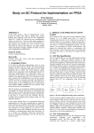
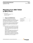
International Journal of Computer Applications (0975 – 8887) Volume 125 – No.9, September 2015 The Design and Development of Controller Software for Scan/DF Subsystem P. Srividya B.I. Neelgar Student GMRIT Rajam Professor GMRIT Rajam ABSTRACT In modern receiver control applications achieving real time response is most important. The paper is a part of software development for CSM controller system. In this paper a real time application, for controlling SCAN/DF receiver simulator will be implemented using POSIX socket APIs on VxWorks RTOS and process the data from the Scan/DF receiver subsystem. The processed data can be used to develop a database for electronic order of battle. This application will be able to interact with receiver using socket APIs, to exchange command and data packets. TCP/IP based socket APIs will be used to realize the application. Keywords Client, Electronic Warfare (EW), POWERPc, Scan/DF receiver, Server, TCP/IP Sockets, VxWorks RTOS. 1. INTRODUCTION This paper discusses about the development of a real time application for controlling of Scan/DF receiver subsystem. The operations of the Scan/DF receiver subsystem include the interception of the signal and report the frequency, direction of arrival, amplitude, time of interception and signal bandwidth between the frequency ranges of 20-1000MHz. this subsystem is connected to Control system through LAN and controlled by server. The server is responsible for the acceptance of the commands from the user and displays the result. To perform such operations a real time application like VxWorks is essential. VxWorks is a hard Real Time Operating System. This application is implemented using POSIX Socket APIs that are used to create a Client-Server environment. This application will interact with user and should be able to send and receive the commands and data packets. The data which is received from Scan/DF receiver will be forwarded to Monitoring Subsystem for the further classification of the signal as the modulation, the monitoring of audio and IF data .Four main functional units of this subsystem are command control subsystem, VxWorks RTOS, Scan/DF receiver subsystem and CHAMP AV4 Board. The command control unit is a simple system through which the user gives command, the receiver subsystem functions are simulated on simple system which is a LINUX operating system, and the Command control unit, VxWorks RTOS and ScanDF Subsystem units are connected through LAN where the data transfer is done using the socket system calls. 2. ELECTRONIC WARFARE (EW) Electronic Warfare (EW) is a catalyst towards the maintenance of regional and global balances which deter the outbreak of armed conflict. EW is not firmly 'electronic', it is not conducted using electrons; rather it is electromagnetic, and uses the entire range of the electromagnetic band. The fundamental concept of EW is to utilize the enemy's electromagnetic emanations in all parts of the electromagnetic band consecutively to provide intelligence on the enemy's order of battle, targets and competences and to use countermeasures to contradict efficient use of communications and weapons systems while defending one's own effective use of the same band. The field of EW is most commonly subdivided into three categories: Electronic Support This Measures (ESM), Electronic Countermeasures (ECM) Electronic CounterCountermeasures (ECCM). Electronic warfare has been used in all major conflict ever since the first phase of this century. Early methods were often prehistoric and it was only from World War II onwards that EW expanded an aspect of complexity and development. Electronic Warfare (EW) Electronic Support Measures Electronic Counter Measures Electronic Counter Counter Measures Figure 1 Electronic Warfare 2.1 Electronic Support Measures (ESM) Electronic Support Measure is a division of EW which engaged to take actions as seek, capture, trace, record and evaluate emitted electromagnetic energy, for the purpose of utilizing such radiations to carry military operations. Thus, ESM is a main source of EW information to accomplish electronic countermeasures and electronic, countercountermeasures. ESM entails the gathering of information by 45 International Journal of Computer Applications (0975 – 8887) Volume 125 – No.9, September 2015 Electronic Intelligence (ELINT), Communications Intelligence (COMINT) and ESM receivers. the listen () and accept () system call. 2.2 Electronic Counter Measures (ECM) Electronic Countermeasures are the measures taken to avoid or diminish the enemy's efficient use of the electromagnetic band. Two major actions of ECM are jamming and deception. Jamming is the purposeful emission, reradiation, or reflection of electromagnetic energy to weaken the use of electronic devices, equipment. Deception is the intentional radiation, re-radiation, modification, assimilation, or reflection of electromagnetic energy in a way planned to deceive the opponent in the explanation or make use of of information received by their electronic systems. read () and Write () the data from the socket and to the socket. 4. ACTUAL SYSTEM The actual system used for Commanding and controlling in Communication Support Measure (CSM) Controller subsystem. The CSM System functional block diagram is shown in Figure 2. The ScanDF Subsystem (SDF), the Monitoring receiver and Analysis Subsystem (MAS), wideband Surveillance Subsystem (WS) and CSM Controller are on an internal bus realized through LAN. Subsystem are controlled and coordinated by the CSM Controller. Intelligence received from these subsystems are processed and formatted into data files and sent to further echelons. There are two categories of deception. Manipulative: The change or imitation of electromagnetic radiations to accomplish deception. SDF friendly Imitative: Introducing radiation into enemy channels which imitates their own emission. 2.3 Electronic Counter Counter Measures (ECCM) The measures in use to make sure friendly, successful, use of the electromagnetic band in spite of the enemy's use of EW is ECCM. The field of EW is converse in stipulations of active and passive roles. Passive EW is to explore and study the electromagnetic emission to determine the existence and the characteristics of the enemy's use of the electromagnetic spectrum. Active EW is the radiation or re-radiation of electromagnetic energy so as to weaken the enemy's use of electronic tools, or to delude the enemy in the interpretation of data received from their electronic schemes. 3. TCP/ IP PROTOCOL BASED SOCKET PROGRAMMING A protocol is a common language that the server system and the client systems both understand. TCP is fine for transporting data across a network. Socket is a method of communication between computers (clients and server) using standard UNIX file descriptors [5]. A Socket is used in client server application frameworks. Client Process is the process which usually makes a request for information. After getting the response this process may conclude or may do some other processing. Server Process is the process which obtains a request from the clients. After getting a request from the client, this server process will do essential processing, congregate the information and will send it to the requestor client [6]. Client process involves the following steps: [6] Creation of socket using socket () call. Connecting the socket to the address of the server using connect () call. write () and read () the data to the socket and from the socket. Server process involves the following steps: [6] Creation of socket using socket () call. Bind the socket to an address using the bind () call. Listen for connections and Accept a connection with CSM Controller LAN Subsystem Switch MAS Subsystem WS Subsystem Figure 2 Actual System 5. FUNCTIOMAL BLOCK DIAGRAM OF Scan D/F SUBSYSTEM Through the operator interface/ command control system the operator will give the command to the system. The operator interface and ChampAV IV are connected through LAN and works on Client Server model where the image of VxWorks is dumped onto ChampAV IV board. The board is connected to the Simulator and the Client-Server model is again implemented. Here VxWorks RTOS is used to display the process running on the board. VxWorks RTOS and Champ AV IV board are connected through LAN and RS-232 cable. The simulated results from the Simulator are displayed on Operator interface through VxWorks. 5.1 Operator Interface System The Operator interface system or command control system based on Linux OS is used to give the commands to the Simulator. The response to the command will be again displayed on the command controller. Operator interface unit is a system through which the operator gives command. Host System VxWorks RTOS [3] is the host system. The host is a Windows XP PC with Wind River 2.5 installed on it. Target System Target is CHAMP AV 4 [4] POWERPc Board with Quad PowerPC 7447A CPUs operating at 1.0 GHz o 64 Kbyte L1 and 512 Kbyte (7447A) L2 internal caches operating at core processor speed 46 International Journal of Computer Applications (0975 – 8887) Volume 125 – No.9, September 2015 256 Mbytes DDR-25O SDRAM with ECC per processor (1 GByte total) VxWorks and then to command control system. 256 Mbytes Flash memory with write protection jumper Set the configuration parameters of ScanDF subsystem as per IRS. 128 Kbytes NVRAM Six Port Gigabit Ethernet switch: The target system (embedded) will forward the commands to the simulator/ Scan/DF subsystem. The Scan/DF subsystem/ Simulator will send the intercepted data to the target system. The target system will forward the data to command control/ operator interface system for the display of received data. o One Gigabit Ethernet port (RGMII) to each of the four processing nodes o Two off-board Gigabit Ethernet ports (1OBase-T/1OOBase-T/1OOOBase-T) VME64x interface Support for two 64-bit, 100 MHz PCI-X mezzanine modules (PMC-X) Four serial ports, one EIA-232 per processor node Support for switch fabric PMC modules with differential routing to backplane Air-cooled ruggedization. Operator Interface (Linux OS) Target Board (Champ AV IV) LAN LAN LAN Simulator (Scan /DF Subsystem ) 6. APPLICATION LEVEL ALGORITHM 6.1 System level Algorithm to communicate between Linux client (command controller) and VxWorks Server Client (command controller) Process: Create () TCP socket. Send connect () to server. After the server accepts the request from the client send the start analysis command to the server, which is developed by the user. Write () the command into buffers. Read () the data packets received from the server which are coming from the simulator (designed by user). Write () the stop analysis command to the server to stop the analysis. RS-232 Client (command controller) Process: Developme nt Host (VxWorks) Figure 3 Block Diagram for Scan / DF Subsystem Ethernet Switch Target System Create () TCP socket. Send connect () to server. After the server accepts the request from the client send the start analysis command to the server, which is developed by the user. Write () the command into buffers. Read () the data packets received from the server which are coming from the simulator (designed by user). Write () the stop analysis command to the server to stop the analysis. 6.2 System level Algorithm to communicate between VxWorks client and Simulator (server) Host System RS-232 Figure 4 Host target Connectivity Client Process: Create () TCP socket. Send connect () to simulator. After the simulator accepts the request from the VxWorks client and send the data in buffers to the simulator. Receive () the data packets received from the simulator. Send () them to the VxWorks server which will be read by the client. 5.2 ScanDF Subsystem The scan/DF receiver subsystem intercepts the signals and reports the frequency, direction of arrival, amplitude, time of interception and signal bandwidth between the frequency ranges of 20-1000MHz. The Scan/DF system works on principle of interferometry. The receiver 5element DF system will find the amplitude and phase difference of signals arrived at the different receivers. When all the signals are in inphase then the interception will starts. The receiver data is send to Simulator (server) Process: 47 International Journal of Computer Applications (0975 – 8887) Volume 125 – No.9, September 2015 Create () TCP socket. Bind () the socket. Listen () for the connections from any VxWorks client. Accept () the request from the client. After the client sends the data into the buffers, receive () the data from the buffers and send the data packets VxWorks client. Those packets will be read by the client (Command controller). When the client (command controller) sends the stop analysis command then stop the intercepting of the signals. 8. RESULTS 7. WORKING OF SUBSYSTEM Once the client server model is implemented between the systems, the user has to configure the parameters as attenuations (rf and if) of signal, threshold level of signal, integration factor for the system. Attenuation of signal is to a reduce strength during transmission to a particular level, for example, if rfattenuation is to set then the user has to select the attenuation level in between 0db and 30db so that the signal will be attenuated. The threshold level is the point that must be exceeded to begin producing the interception; here the threshold level must be in between -120Hz and 40Hz. The integration factor is to define the number of times the interception is needed. After the configuration of parameters is set, the user from client (operator interface) has to fix the resolution bandwidth so that the simulator will check the frequencies of signals with a difference of resolution bandwidth. When the resolution bandwidth is also set then the client will pass the start analysis command to the embedded system which acts as both server and client for the subsystem. Here VxWorks is used to prioritize the tasks between monitoring of signal and Scanning the scenario. The image that is developed in VxWorks will be dumped on to ChampAV IV board. The image for ScanDF subsystem will be sent to one of the processors in quad POWERPc board through which the commands from client (operator interface) will be sent to ScanDF simulator (server). Figure 5 input command and outputs on Command controller The ScanDF system will continuously scan the scenario. The ScanDF subsystem will do both the scanning of the signal and finding the direction of arrival of the signals at a same time for a given frequency. The embedded system will filter and process the data for the intercepting needs. For example it will do band filtering and AOI filtering. AOI filtering means it filters the data in an area by intercepting the area in sectors. Until the stop analysis command is given by the user it will scan the scenario and process the data packets; if analysis by user is without DF (Direction Finding) mode then only the amplitude packet data that is about the amplitude packet frequency, Power level, time of interception and noise level of the signal will be sent by the simulator through embedded system, If the analysis selected by the user is with DF mode then the simulator will send the data about direction packet data that is about the direction packet frequency, power level, noise level, direction of arrival and the time of interception of the signal. Figure 6 Simulation of system for the given Scan command 48 International Journal of Computer Applications (0975 – 8887) Volume 125 – No.9, September 2015 Figure 9 the output displayed on VxWorks After burning the image on ChampAV IV Figure 7 input command and outputs on Command controller The screenshots as in Figure 5, Figure 6, Figure 7, and Figure 8 indicate the results of the data that is intercepted by the Scan/DF Subsystem. The data from Subsystem is send to the embedded controller (target) for further process and it will be forwarded to operator interface for display and for the use of information at the higher echelons. After the client (Command controller) got the acceptance from the Embedded Server the setting of parameters is displayed on the screenshot. When the start analysis command is given by the operator the simulated result from the server (Simulator) will be displayed on the screen of Command control are shown in Figure 5. After the Client is accepted by the server (Simulator), when the start analysis command is read by the server the simulation will starts and the data is send to client, the process is shown in Figure 6. Figure 5 represents the display on client process; here mode value is given as 1 which means only Scan mode. Figure 7 represents the display on client process; here mode value is given as 2 which means Scan/DF mode. The Figure 9 points to the outputs displayed on the screen of VxWorks RTOS after the VxWorks image is dumped and burned onto ChampAV IV board. The screenshots as in Figure 5 and Figure 7 indicate the results of the data that is intercepted by the ScanDF Subsystem. The data from Subsystem is send to the embedded controller (target) for further process and it will be forwarded to operator interface for display and for the use of information at the higher echelons. After the client (Command controller) get acceptance from the Embedded Server the setting of parameters is displayed on the screenshot, when the start analysis command is given by the operator the simulated result from the server (Simulator) will be displayed on the screen of Command control are shown in Figure 5 and Figure 7 as per the given mode of operation. The Client is accepted by the server (Simulator), when the start analysis command is read by the server the simulation will starts and the data is send to client, the process is shown in Figure 6 and Figure 8. 9. CONCLUSION Figure 8 Simulation of system for the given Scan/DF command The paper is a part of controller software development for CSM controller system. The main functionality of the CSM software is to command and control various receiver subsystems. The software acts as server for various subsystems and provides necessary data for display. The basic concept of electronic warfare is to exploit, intercept, reduce or prevent hostile use of electromagnetic spectrum and action which retains friendly use of electromagnetic spectrum. The threat warning function is many times coupled with a defensive capability in the form of a self protection jammer in 49 International Journal of Computer Applications (0975 – 8887) Volume 125 – No.9, September 2015 combination with decoys which can divert weapons from the defended target. It is to keep track of the enemy even in the peacetime because unfortunately some very important signals may be passed this might lead to war. In modern receiver control applications achieving real time response is of prime importance. In this paper a real time application for controlling SCAN receiver, will be implemented using POSIX socket APIs on VxWorks RTOS. This application must be able to interact with receiver using socket APIs, to exchange command and data packets. TCP/IP based socket APIs will be used to realize the application. The functioning of the Scan Receiver under different cases is examined and the result for each function is displayed. The paper is tiny part of our present Electronic Warfare system. 10. REFERENCES [2] Richard poisel “Introduction to communication Electronic warfare systems” 1st feb 2002. [3] Alameda “Windriver systems Inc, Tornado User’s guide”,CA: windriver systems,Inc,1999 [4] Compact CHAMP-AV IV QUAD POWERPCTM (SCP424) user manual [5] Richard stevens “UNIX Network programming” VOL 1 third edition [6] Keith Gaughan “Client-Server TCP/IP Sockets” March 22, 2003. Programming with [7] Rias muhamed ”Thesis on Directional of arrival estimation using antenna arrays” January 1996. [1] D.curtis schleher “introduction to electronic warfare”, December 1,1986 IJCATM : www.ijcaonline.org 50