1
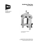
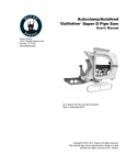
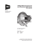
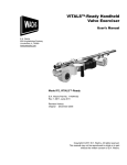
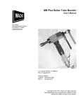
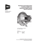
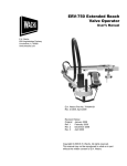
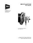
SDB 206 and FF 313 User’s Manual E.H. Wachs 600 Knightsbridge Parkway Lincolnshire, IL 60069 www.ehwachs.com E.H. Wachs Part No. 56-MAN-01 Revision B September 2013 Copyright © 2013 E.H. Wachs. All rights reserved. This manual may not be reproduced in whole or in part without the written consent of E.H. Wachs. EU Declaration OF CONFORMITY WITH COUNCIL DIRECTIVE 2006/42/EC Issue Details: Directives: DATE: Place: 1/1/2011 E.H.Wachs, Lincolnshire, IL USA Machinery Safety Directive 2006/42/EC Conforming Machinery: End Prep and Flange Facing Machines: Model TSE, FSE and TFS Tube and Fitting Squaring Machines Model SDB 103, SDB 206, and SDB 412 Small Diameter Bevelers; Model FF 206, FF 313, and FF 424 Flange Facers. Model SB, LB, and MB Plus Boiler Tube Bevelers. EP 424 End Prep/Flange Facer. Model Number: 18-000-XX (TSE, FSE); 19-000-XX (TFS); 16-000-XX) (SDB103/FF-206); 56-000-XX (SDB-206/FF313); 66-000-XX (SDB412/FF-424); 70-000-XX (SB); 71-000-XX (MB Plus); 72-000-XX (LB); 81-000-XX (EP 424). Serial Number: Manufacturer: E.H. Wachs 600 Knightsbridge Parkway Lincolnshire IL 60069 USA Responsible Representative: Orbitalum Tools GmbH Josef-Schüttler-Str. 17, 78224 Singen Germany Tel. +49 (0) 7731 - 792 872 Fax +49 (0) 7731 - 792 566 Harmonised Standards & EN ISO 12100-1:2003 + A1:2009 EN ISO 12100-2:2003 + A1:2009 Other Technical EN 60204-1:2006 (for electric machines) Standards/Specifications EN ISO 13857:2008 Applied or Referenced: EN 982:1996 + A1:2008 (for hydrailic machines) EN 983:1996 (for pneumatic machines) EN 13732-1:2006 EN ISO 14121-1:2007 EN ISO 13850:2008 (for pneumatic machines) Provisions with which Essential Health and Safety Requirements of Annex 1 of the Conformity is Declared: Machinery Directive We hereby certify that the machinery described above conforms to the provisions of Council Directive 2006/42/EC on the approximation of the laws of the Member States relating to the safety of machinery. Signed: Signatory: Pete Mullally Quality Manager E.H. Wachs Introduction to the Equipment Introduction to the Equipment The SDB 206/2 is a hand-held beveling machine for fast, accurate weld preps on pipe and tube from 2.27" inside diameter (I.D.) to 6" outside diameter (O.D.). It can machine pipe or tube with wall thickness up to 0.75". The machine clamps to the I.D. of the pipe being machined using a three-leg mandrel design for square, rigid installation. Different sized clamp legs are used to cover the machine’s entire range of pipe diameters. Machine Description Figure 1-1 illustrates the main components of the SDB 206. Chuck Lift handle Mandrel Rotating head Air motor Feed handle Drawbar nut Figure 1-1. The photo illustrates the components of the SDB 206. E.H. Wachs Company Part No. 56-MAN-01, Rev. B1 SDB 206 and FF 313 Rotating Heads and Mandrels The rotating head is equipped with four tool holders that allow up to four form tools to be used simultaneously. You can face, bevel, and counterbore in one machining operation. Once you have configured the tooling for a particular pipe size, you can easily move the machine from one pipe to the next with no additional setup required. Three different sized rotating heads and four styles of mandrels are available with the SDB 206. The three rotating heads are shown in Figure 1-2. The standard mandrel is shown in Figure 1-3. Small head (56-004-00) Large 8" head (56-076-00) Standard head (56-005-00) Figure 1-2. The photo shows the three rotating heads available with the SDB 206. Chuck body Drawbar nut Chuck leg Feed threads Figure 1-3. The photo shows the SDB 206 mandrel. 2 Part No. 56-MAN-01, Rev. B E.H. Wachs Introduction to the Equipment: Machine Description Mechanical Drives The SDB 206 has two mechanical drives: cutting rotation and feed. The standard cutting drive for the SDB 206/2 is a 2.5 HP air motor. Optional electric and hydraulic drives are also available. The feed drive is manually operated using a convenient handle. A feed index gauge provides precise feed measurement. Figure 1-4. The feed drive includes a four-post handle and a gauge for measuring feed distance. Clamping Legs The standard chuck legs built into the mandrel allow an I.D. clamping range of 2.27" to 2.92". Seven standard sets of leg extensions are provided to extend the pipe I.D. capacity of the standard machine up to 6.77". There are three identical legs in each set. Table 1: Standard Extension Leg Sets Part No. E.H. Wachs Leg Thickness Pipe I.D. Range 56-085-01 0.24" 2.75"-3.37" 56-085-02 0.52" 3.31"-3.94" 56-085-03 0.80" 3.87"-4.50" 56-085-04 1.09" 4.44"-5.07" 56-085-05 1.37" 5.01"-5.63" 56-085-06 1.64" 5.55"-6.19" 56-085-07 1.94 6.14"-6.77" Part No. 56-MAN-01, Rev. B3 SDB 206 and FF 313 An optional set of extended range legs can be used to extend the pipe I.D. capacity up to 9.04". Note that, to operate on pipe O.D.s over 6", you will need to install the optional 8" diameter head (56-076-00). Table 2: Extended Range Leg Sets Part No. Leg Thickness Pipe I.D. Range 56-085-08 2.22" 6.71"-7.34" 56-085-09 2.51" 7.28"-7.91" 56-085-10 2.79" 7.85"-8.48" 56-085-11 3.08" 8.42"-9.04" Extended range leg sets Standard leg sets Figure 1-5. The photo shows the standard leg sets (front) and extended range leg sets (back). 4 Part No. 56-MAN-01, Rev. B E.H. Wachs Introduction to the Equipment: Machine Description Figure 1-6. The pipe I.D. diameter range is stamped on each leg set. Each leg has two captivated mounting screws that attach the leg to the chuck leg on the mandrel. Figure 1-7. The screws in the clamp leg attach it to the chuck leg on the mandrel. Noise Levels The following noise levels were measured at 1 m high and 1.6 m from the machine. Average sound level 62 dBA Maximum sound level 89 dBA E.H. Wachs Part No. 56-MAN-01, Rev. B5 SDB 206 and FF 313 Specifications Pipe capacity 2.27" I.D. to 6.77" I.D. (up to 9.04" with extended range kit 56-430-03) Pipe wall thickness Up to 0.75" Controls —Manual feed with index gauge for measurement —On/off fail-safe motor lever —Motor speed control Feed rate 0.08" (2 mm) per revolution Feed stroke 2.5" usable feed travel Drive options —Air (70 cfm @ 90 psi) —Hydraulic (8 gpm @ 1500 psi) —Electric (110 V or 220 V) Tool RPM 0 to 40 Tooling Standard or high-range tool holder with high-speed steel inserts; carbide available Tool slots 4 (all rotating head options) Dimensions Length: 9" without mandrel; 19" with mandrel Width: 11.5" Height: 27.5" with air motor Weight 42 lb with mandrel and air motor 6 Part No. 56-MAN-01, Rev. B E.H. Wachs Introduction to the Equipment: Operating Envelopes and Tooling Charts Operating Envelopes and Tooling Charts This section includes the following information for using the SBD 206 and FF 313: • operating envelope for the SDB 206 and FF 313 machine configurations, mandrels, and extension legs • tooling charts for beveling, counterboring, J-prepping, and deburring. E.H. Wachs Part No. 56-MAN-01, Rev. B7 SDB 206 and FF 313 8 Part No. 56-MAN-01, Rev. B E.H. Wachs Introduction to the Equipment: NOTE: DETAIL-A SDB 206, Air Drive (56-000-01) E.H. Wachs Part No. 56-MAN-01, Rev. B9 SDB 206 and FF 313 NOTE: SDB 206, Electric Drive (56-000-02) 10 Part No. 56-MAN-01, Rev. B E.H. Wachs Introduction to the Equipment: NOTE: SDB 206, Hydraulic Drive (56-000-03) E.H. Wachs Part No. 56-MAN-01, Rev. B11 SDB 206 and FF 313 DIMENSIONS IN BRACKETS ARE MILLIMETERS FF 313, Air Drive (56-000-FF) 12 Part No. 56-MAN-01, Rev. B E.H. Wachs Introduction to the Equipment: Standard Mandrel and Extension Legs (56-430-00) DIMENSIONS IN BRACKETS ARE MILLIMETERS NOTE: E.H. Wachs Part No. 56-MAN-01, Rev. B13 SDB 206 and FF 313 Beveling Tool Chart ANGLE MAX WALL .063 LAND O.D. I.D. NOTE: (1) TOOL RETAINED WITH AT LEAST 2 SCREWS ON STANDARD ROTATING HEAD. BEVEL TOOL FACING TOOL ANGLE W/ 1/16" LAND W/ 1/16" LAND MIN I.D. MAX I.D. (1) W/1/16" LAND MAX O.D. (1) 1.38" (35.1mm) 2.26" (57.4mm) 4.88" (124.0mm) 7.60" (193.0mm) 3.03" (77.0mm) 2.26" (57.4mm) 3.48" (88.4mm) 6.18" (157.0mm) 4.88" (124.0mm) 7.60" (193.0mm) 7.84" (199.1mm) 7.84" (199.1mm) MAX WALL 56-709-03 56-709-03 56-708-01 56-708-02 37-1/2 37-1/2 56-709-02 56-708-01 56-708-02 30 0.73" (18.5mm) 1.50" (38.1mm) 30 0.53" (13.5mm) 56-709-02 6.60" (167.6mm) Counterbore Tool Chart 14° COUNTERBORE I.D. DEPTH 14 PIPE I.D. NOTE: (1) TOOL RETAINED WITH AT LEAST 2 SCREWS ON STANDARD ROTATING HEAD MAX DEPTH C'BORE TOOL MIN PIPE I.D. MIN C'BORE I.D. MAX C'BORE I.D.(1) MAX DEPTH W/56-708-01 FACING TOOL 56-705-01 2.38" (60.5mm) 3.50" (88.9mm) 2.62" (66.5mm) 0.48" (12.2mm) 3.75" (95.3mm) 5.88" (149.4mm) 7.00" (177.8mm) 0.63" (16.0mm) 56-705-02 0.63" (16.0mm) 0.48" (12.2mm) 56-705-03 4.50" (114.3mm) 4.75" (120.7mm) 8.00" (203.2mm) 0.63" (16.0mm) 0.48" (12.2mm) Part No. 56-MAN-01, Rev. B E.H. Wachs Introduction to the Equipment: J-Prep Tool Chart 20° R.094 2.4 MAX WALL O.D. I.D. .063 LAND 1.6 .15 LAND EXTENSION 3.8 NOTE: (1) TOOL RETAINED WITH AT LEAST 2 SCREWS ON STANDARD ROTATING HEAD. BEVEL TOOL FACING TOOL MAX WALL W/ 1/16" LAND W/ 1/16" LAND MIN I.D. MAX I.D. (1) MAX O.D. (1) 56-709-01 56-709-05 56-708-01 1.68" (42.7mm) 1.68" (42.7mm) 2.38" (60.5mm) 2.38" (60.5mm) 5.00" (127.0mm) 6.28" (159.5mm) 8.09" (205.5mm) 9.61" (244.1mm) 56-708-01 W/1/16" LAND Deburring Tool Chart 10° PIPE I.D. NOTE: (1) STANDARD ROTATING HEAD E.H. Wachs DEBURRING TOOL MIN PIPE I.D. MAX PIPE I.D.(1) 56-702-01 2.26" (57.4mm) 56-702-02 2.64" (67.1mm) 5.28" (134.1mm) 5.88" (149.4mm) 56-702-03 3.26" (82.8mm) 6.50" (165.1mm) Part No. 56-MAN-01, Rev. B15 SDB 206 and FF 313 16 Part No. 56-MAN-01, Rev. B E.H. Wachs Safety Safety The E.H. Wachs Company takes great pride in designing and manufacturing safe, high-quality products. We make user safety a top priority in the design of all our products. Read this chapter carefully before operating the SDB 206 or FF 313. It contains important safety instructions and recommendations. Safe Operating Guidelines Follow these guidelines for safe operation of all E.H. Wachs equipment. Look for this symbol throughout the manual. It indicates a personal injury hazard. • READ THE OPERATING MANUAL. Make sure you understand all setup and operating instructions before you begin. Keep this manual with the machine. • INSPECT MACHINE AND ACCESSORIES BEFORE USE. Before starting the machine, look for loose bolts or nuts, leaking lubricant, rusted components, and any other physical conditions that may affect operation. Properly maintaining the machine can greatly decrease the chances for injury. • ALWAYS READ STICKERS AND LABELS. Make sure all labels and stickers are in place, clearly legible, and in good condition. Refer to “Safety Labels” later in this chapter for label locations on the machine. Replace any damaged or missing safety labels; see Chapter 10 for ordering information. • KEEP CLEAR OF MOVING PARTS. Keep hands, arms, and fingers clear of all rotating or moving parts. Always turn the machine off and disconnect the power source before doing any adjustments or service. • SECURE LOOSE CLOTHING AND JEWELRY. Secure or remove loose-fitting clothing and jewelry, and securely bind long hair, to prevent them from getting caught in moving parts of the machine. • FOLLOW SAFE PROCEDURES FOR HANDLING LUBRICANTS. Refer to the manufacturer’s instructions and the Material Safety Data Sheets. E.H. Wachs Part No. 56-MAN-01, Rev. B17 SDB 206 and FF 313 Safe Operating Environment • Do not use this equipment in a potentially explosive atmosphere. Fire or explosion could result, with the risk of serious injury or death. • Provide adequate lighting to use the equipment, in accordance with worksite or local regulations. • KEEP WORK AREA CLEAR. Keep all clutter and nonessential materials out of the work area. Only people directly involved with the work being performed should have access to the area. Operating and Maintenance Safety • This equipment is to be operated and maintained only by qualified, trained personnel. • Make sure the equipment is stable when attached to the workpiece for the operation. Ensuring stability of the installed tool is the responsibility of the operator. • Make sure the workpiece is supported adequately for installation of the equipment. This includes supporting any workpiece “fall-off” section when severing the workpiece. Ensuring support of the workpiece is the responsibility of the operator. • Tooling on any cutting equipment—including lathe tools, saw blades, milling tools, etc.—may get very hot. Do not touch tooling until you have made sure it is cool enough to handle. • Wear gloves when removing or cleaning up chips and cutting debris. Chips can be very sharp and cause cuts. • Before performing any service on the equipment, disconnect the power source. Follow all lock-out/tag-out procedures required at the worksite. Hydraulic Powered Equipment • Hydraulic components such as hoses, motors, and manifolds will get hot during operation and may cause burns. Do not touch hydraulic components, except for operator controls, during or after operating the machine. WARNING Injection of hydraulic fluid through the skin is a serious injury that can result in infection, tissue damage, and possible loss of limb. Seek medical treatment immediately. First aid is not sufficient treatment for injection injury. • Hydraulic injection injury—A pinhole in a hydraulic hose or fitting can eject fluid with enough force to pierce skin. Check hoses and fittings regularly for leaks. Do not use bare hands to check for leaks while the system is pressurized. If you suspect a leak, move a piece of paper or cardboard at least 6 inches (15 cm) over the suspicious area and watch for fluid spraying on the surface. 18 Part No. 56-MAN-01, Rev. B E.H. Wachs Safety: Safe Operating Guidelines Pneumatic Powered Equipment • Air motors may get hot during operation and may cause burns. Do not touch the air motor, except for operator controls, during or after operating the machine. • Before disconnecting the air line from the equipment, always turn off air at the source and bleed all residual air pressure at the air motor. Loss or Shut-Off of Power Supply For all power sources, follow all lock-out/tag-out procedures required at the worksite when disconnecting or servicing the equipment. • PNEUMATIC POWERED EQUIPMENT—Disconnect the air supply from the machine after loss of power to prevent accidental restarting of the machine. Lock out the power supply immediately. • HYDRAULIC POWERED EQUIPMENT—Disconnect hydraulic lines from the hydraulic manifold to prevent accidental restarting of the machine. Lock out the power supply immediately. • ELECTRIC POWERED EQUIPMENT—If the electric drive shuts off because of its built-in thermal protection, disconnect the motor from the power source immediately. Safety Alerts in This Manual The following alerts are used throughout this manual to indicate operator safety hazards. In all cases, these alerts include a notice describing the hazard and the means to avoid or reduce risk. Carefully read all safety alerts. This icon is displayed with any safety alert that indicates a personal injury hazard. WARNING This safety alert indicates a potentially hazardous situation that, if not avoided, could result in death or serious injury. CAUTION This safety alert, with the personal injury hazard symbol, indicates a potentially hazardous situation that, if not avoided, could result in minor or moderate injury. E.H. Wachs Part No. 56-MAN-01, Rev. B19 SDB 206 and FF 313 Protective Equipment Requirements Protective Clothing Wear safety shoes when operating or servicing the equipment. Serious injury could result from dropping the machine or its components. Do not wear gloves while operating the machine. Gloves can become entangled in moving parts, resulting in serious injury. Gloves may be worn when setting up the machine or cleaning up after the operation, but take them off when operating the machine. NOTE Gloves should be worn when cleaning up chips and other cutting debris. Chips can be very sharp and can cause serious cuts. Do not wear gloves when the machine is operating. Eye Protection Always wear impact-resistant eye protection while operating or working near this equipment. 20 Part No. 56-MAN-01, Rev. B E.H. Wachs Safety: Safety Labels For additional information on eye and face protection, refer to Federal OSHA regulations, 29 Code of Federal Regulations, Section 1910.133., Eye and Face Protection and American National Standards Institute, ANSI Z87.1, Occupational and Educational Eye and Face Protection. Hearing Protection This equipment can produce noise levels above 80 dB. Hearing protection is required when operating the equipment. The operation of other tools and equipment in the area, reflective surfaces, process noises, and resonant structures can increase the noise level in the area. For additional information on hearing protection, refer to Federal OSHA regulations, 29 Code of Federal Regulations, Section 1910.95, Occupational Noise Exposure and ANSI S12.6 Hearing Protectors. Safety Labels The following safety labels are provided on the SDB 206/FF 313. If any of these labels is damaged or missing, replace it immediately. See the section on ordering information at the end of this manual. Figure 2-1. The Keep Hands Clear warning label is on the bearing housing of the SDB 206/ FF 313. (Part no. 66-147-00.) E.H. Wachs Part No. 56-MAN-01, Rev. B21 SDB 206 and FF 313 Figure 2-2. The ear and eye protection label is attached to the air and electric drives of the SDB 206/FF 313. Always wear ear and eye protection when operating the equipment. (Part no. 90-401-03.) Figure 2-3. The eye protection label is attached to the hydraulic drive of the SDB 206/FF 313. Always wear eye protection when operating the equipment. (Part no. 90-401-01.) Figure 2-4. The air pressure label is attached to the air drive of pneumatic SDB 206/FF 313 models. Do not operate the equipment with greater than 90 psi (6.2 bar) air pressure. (Part no. 90-401-02.) 22 Part No. 56-MAN-01, Rev. B E.H. Wachs Safety: Safety Labels Figure 2-5. The hydraulic pressure label is attached to the SDB 206/FF 313 hydraulic drive. Do not operate the equipment with greater than 2000 psi (138 bar) hydraulic pressure. (Part no. 90-402-01.) Figure 2-6. The hot surface label is attached to the SDB 206/FF 313 hydraulic and electric drive motors. Drive components may become hot enough to cause burns. Make sure they are not hot before touching them. (Part no. 90-403-00 [small]; 90-403-02 [large].) E.H. Wachs Part No. 56-MAN-01, Rev. B23 SDB 206 and FF 313 24 Part No. 56-MAN-01, Rev. B E.H. Wachs Small Diameter Beveler SDB206/2 Small Diameter Beveler Setup & Operation SDB 206 Mandrel Selection The SDB206 uses two different size heads to cover its machining range. For machining workpieces 2.28" through 4-3/8" I.D., the optional small head is used. The large head is used on pipes over 3-7/8" I.D. These mandrels have three legs which expand equally to contact the inside walls of the workpiece when the draw bolt is tightened. Measure the pipe I.D. that is to be prepared. Turn to page six (6) to select the proper mandrel leg extension. The leg extensions are stamped with a reference number to indicate size of pipe that they will fit. Once you have determined the mandrel arrangement that is required, attach leg extensions to the blade with the captive screws. NOTE A light oil coating on the mandrel will give a longer life and smoother operation. E.H. Wachs Company Part No. 56-MAN-01, Rev. B25 SDB 206 and FF 313 Mandrel Placement Inspect the bore of the beveling head for dirt and metal chips. Clean the bore with compressed air or solvent as necessary. Wipe the mandrel clean and apply a light coating of oil. Being careful not to scrape the head bushing, insert the threaded end of the mandrel through the front of the beveling head (Figure 3-1). Figure 3-1. 26 Part No. 56-MAN-01, Rev. B E.H. Wachs Small Diameter Beveler: Setup & Operation When the threads contact the inside of the feed nut, turn it clockwise until the draw bar nut is completely exposed. Be certain to align the key in the end cap to the key way of the mandrel. Use the two locking set screws located on either side of the machine body to apply tension to the machine and mast (Figure 3-2). This will remove any play, and pre-load the machine to the mast. Figure 3-2. E.H. Wachs Part No. 56-MAN-01, Rev. B27 SDB 206 and FF 313 Tooling Set-Up CAUTION Disconnect the air supply whenever changing or adjusting the form tools. Install the facing tool in the Rotating head. Refer to Tool Charts for the appropriate tool bit. All tool bits must be installed so the cutting edge will contact the pipe when rotating in a clockwise direction, as seen from rear of machine. The tool bits are locked into place with the set screws adjacent to the slot (Figure 3-3). DO NOT allow tool to come in contact with mandrel or damage may result. Figure 3-3. 28 Part No. 56-MAN-01, Rev. B E.H. Wachs Small Diameter Beveler: Setup & Operation Mounting Machine Into The Pipe Insert the blade end of mandrel into the pipe. For best results keep the end of the blades as close to the pipe edge as practical. The maximum depth of penetration into the pipe should be 3/4" (19mm) from the tapered ends of the leg to the end of the pipe. Be certain that there is adequate clearance between the blades and the I.D. tooling. This will allow for a normal prep and still keep the beveling head rigid. Figure 3-4. With one hand, hold machine concentric to pipe. At the same time, tighten draw bar nut to 70 ft. lb (Figure 3-4). Move the machine back and forth and up and down while tightening. The chuck legs will automatically center the machine. Connect a clean, dry, 90 psi (6 bar) air supply to machine. Start machine and turn feed nut in until cutting tool contacts the pipe. Continue facing until pipe has a clean finish. Retract the beveling head and insert O.D. beveling tool. Start machine and feed beveling tool into the pipe until facing tool touches again. Adjust O.D. beveling tool in or out radially depending on the land thickness desired. The last tool bit to install is the I.D. deburring tool. It should be placed in the slot opposite the beveling tool. It may also require adjustment, in or out, to produce the desired height and depth. NOTE If only two tools are to be used, place them in opposite slots to offset cutting load. E.H. Wachs Part No. 56-MAN-01, Rev. B29 SDB 206 and FF 313 Continuous Operation Once the cutting tools are in place, the machine can be moved from one pipe to another of the same size without resetting the tool bits. To do this, loosen the draw bar nut until mandrel is free. Place machine in the next pipe to be prepped and lock the mandrel. Turn on machine and feed in until desired prep is achieved (Figure 3-5). Figure 3-5. Tips For Good Finish 1. Always place mandrel as close to pipe end as possible. 2. Use a cutting oil or other coolant generously. This will also increase cutter life. 3. Adjust cutting head RPM for material. A good rule of thumb is the harder the material, the slower the speed. 4. Always keep a lot of pressure on the feed nut and pull out of cut quickly when prep is finished. 5. Do not attempt to get a better finish by lightly feeding the tools. 6. Change tool bits or re-sharpen when they become dull. 30 Part No. 56-MAN-01, Rev. B E.H. Wachs Small Diameter Beveler: Setup & Operation SDB to Flange Facer Conversion Procedure 1. Remove the mandrel from the machine body. 2. Using the provided hex key set, remove the Rotating Head by loosening and removing the four-5/16-18 x 3/4" stripper bolts (Figure 3-6). Figure 3-6. 3. Install the Trip Collar assembly by tightening the six locking set screws (Figure 3-7). Figure 3-7. E.H. Wachs Part No. 56-MAN-01, Rev. B31 SDB 206 and FF 313 4. Mount the Flange Facer tool slide by tightening the four-5/16-18 x 5/8" stripper bolts (Figure 3-8). Figure 3-8. 5. Install the Flange Facing Mandrel into the flange I.D. using the alignment fixture to insure proper squareness to flange. Once the mandrel has been properly aligned, mount the machine body to the mandrel (Figure 3-9). Figure 3-9. 32 Part No. 56-MAN-01, Rev. B E.H. Wachs Small Diameter Beveler: Setup & Operation Flange Facing Conversion Setup & Operation 1. Measure the flange I.D. Refer to mandrel leg extension chart. To select the mandrel adaptor and leg Set required to mount in flange I.D. 2. Insert the solid leg set # 56-135-12 in the mandrel head POINT SIDE DOWN (Figure 3-10) NOTE 56-135-12 solid leg set is required when installing the 56-144-00 adapter cone onto the mandrel head. Figure 3-10. E.H. Wachs Part No. 56-MAN-01, Rev. B33 SDB 206 and FF 313 3. Mount the selected adapter over the mandrel head and secure with 3 7/16-20 x 1-1/2 SHCS (Figure 3-11) Figure 3-11. 4. Select extension leg set required. Refer to the I.D. range chart decal provided on the leg extension box, or on page in this manual (Figure 3-12). Figure 3-12. 34 Part No. 56-MAN-01, Rev. B E.H. Wachs Small Diameter Beveler: Setup & Operation 5. Install the adjustment screw into the adjustable leg and tighten completely. (Figure 3-13) Figure 3-13. ABOUT THE ADJUSTABLE LEG An adjustable leg has been provided to compensate for centering on slip over flanges or butt welded flanges when mandrel leg placement must be inside the pipe I.D. 6. Insert the leg set into the adapter. (Figure 3-14) Figure 3-14. E.H. Wachs Part No. 56-MAN-01, Rev. B35 SDB 206 and FF 313 7. Place the mandrel assembly into the flange I.D. with one leg at the 6 o'clock position. The legs should be kept as close as possible to the flange I.D. edge, yet back far enough to perform the desired operation. Snug the mandrel into place by tightening the draw bar nut with the supplied 1-1/8" wrench (Figure 3-15). NOTE Observe the mandrel keyway slots. When the slots are at the nine o'clock and three o'clock position the flange facer motor position can be placed at the six o'clock or twelve o'clock location. Position the mandrel slots at the desired location for air motor clearance or operation. Figure 3-15. 36 Part No. 56-MAN-01, Rev. B E.H. Wachs Small Diameter Beveler: Setup & Operation 8. Slide the flange alignment fixture over the mandrel shaft. (Figure 3-16). Figure 3-16. 9. Extend the alignment arms, if necessary, with the supplied hex key set. (Figure 3-17). Figure 3-17. E.H. Wachs Part No. 56-MAN-01, Rev. B37 SDB 206 and FF 313 10.Loosen the mandrel assembly using the draw bar nut and push the alignment fixture firmly against the flange face. Retighten the draw bar nut with the supplied 1-1/8" wrench. (Figure 18) Remove alignment fixture. NOTE The alignment fixture automatically squares the mandrel to the flange surface, and assures precise square cut. Figure 3-18. 38 Part No. 56-MAN-01, Rev. B E.H. Wachs Small Diameter Beveler: Setup & Operation 11.Install the flange facing machine on the mandrel shaft. Be sure to wipe the mandrel clean. NOTE Align the internal machine keys with the mandrel keyway slots. Engage the internal machine keys on the mandrel keyway slots. Push the machine forward. Rotate the handle assembly clockwise, engaging the machine feed nut into the threaded portion of the mandrel shaft. (Figure 3-19) Figure 3-19. E.H. Wachs Part No. 56-MAN-01, Rev. B39 SDB 206 and FF 313 12.Install the tooling in to the flange facer tool slide slot. (Figure 3-20). Refer to the tool holder/ tool bit diagram. Figure 3-20. 13.Tighten the tool bit locking set screws with the supplied hex key set. (Figure 3-21) Figure 3-21. 40 Part No. 56-MAN-01, Rev. B E.H. Wachs Small Diameter Beveler: Setup & Operation 14.Attach the air supply. Press the air motor lever and rotate the machine slowly, to verify clearance. (Figure 3-23) IMPORTANT E.H. Wachs Co. recommends the use of an ATM air treatment module (pn 26-407-00) to filter air and lubricate the air motor. The air motor warranty will be void if an ATM is not used. Figure 3-22. E.H. Wachs Part No. 56-MAN-01, Rev. B41 SDB 206 and FF 313 15.Set the throttle control valve. The FF 313 is equipped with a throttle control valve to meter the air flow to the motor. Rotating the throttle clockwise will open the valve, counter clockwise rotation will close the valve. (Figure 3-23) Figure 3-23. 16.Rotate the starwheel nut with the supplied 3/4" socket and ratchet, (Figure 3-24) until the tool bit tip is flush with the desired surface to be faced. (Figure 3-25). NOTE Adjust the cutting head RPM with the throttle control for flange size being machined. 3 to 4 RPM recommended for 10" to 13" flange O.D. Increase RPM as flange sizes become smaller. Figure 3-24. 42 Part No. 56-MAN-01, Rev. B E.H. Wachs Small Diameter Beveler: Setup & Operation Figure 3-25. 17.Rotate the axial feed handle assembly clockwise until the tool bit just touches the desired surface to be faced. 18.Again rotate the tool slide starwheel nut, raising the bit just above the surface to be faced. 19.Using the infeed indice gauge, rotate the axial feed handles clockwise until the desired depth of cut is attained. (Figure 3-26) Figure 3-26. E.H. Wachs Part No. 56-MAN-01, Rev. B43 SDB 206 and FF 313 20.Tighten the machine /mandrel locking set screws with the provided hex key set. (Figure 3-27) Figure 3-27. 21.Engage the desired number of trips on the trip collar*. assembly to achieve the surface finish required. (Figure 3-28) (Refer to flange surface trip chart.) Figure 3-28. NOTE Take light cuts to clean up the flange face. To produce a 500 RMS or record groove finish, best results are achieved with a finish cut depth of .007" to .008" 44 Part No. 56-MAN-01, Rev. B E.H. Wachs Small Diameter Beveler: 22.* Time the starwheel. In order to prevent damage to machine, the star wheel must be timed prior to engaging any trips. (Figure 29) Figure 3-29. 23.The machine is now ready to cut. Press the air motor lever to begin cutting. Tips For a Good Finish Single Point Flange Facing/Beveling Module 1. Always place mandrel as close to pipe end as possible. 2. Use cutting coolant generously. This will also increase cutter life. 3. CHATTER: Tool chatter occurs when the tool begins to vibrate during cut. Excessive tool chatter can cause poor quality surface finishes. Chatter can be caused by any one of a number of variables inherent in a portable machine of this type. 4. INTERMITTENT CUTS: When working on a rough cut end of a piece of pipe or a warped flange, tou will need to do an intermittened cut. In order to prolong tool life and reduce shock loads on the machine and inserts, intermittent cuts should be performed at a slower feed rate. Once a full cut is achieved, operating speeds can be increased to normal. 5. As you finish a pass, note your location on the indiced axial feed gauge. Take your next pass; rotate the feed handle backwards one full turn to your noted location and retract your tool slide. Once retracted, rotate the feed handle in the amount you wish for the cut depth of your next pass. This will allow you to retract the slide without damaging the tooling, remove all backlash in the feed handle and give you an exact depth of cut on your next pass. E.H. Wachs Part No. 56-MAN-01, Rev. B45 SDB 206 and FF 313 6. To produce a 500 RMS or record groove finish, the best results are achieved with a finish cut depth of .007" to .008". Manual Bevel Generation Using Single Point Module A bevel can be generated with the Flange Facing Module by feeding the cutting tool into the work radially and axially simultaneously. As the radial feed advances the tool automatically, the operator must withdraw the tool by rotating the axial feed handle counterclockwise. The correct amount of axial feed per machine revolution is given on the following chart. TRIP ENGAGEMENT RMS FINISH 1 TRIP 63 RMS 2 TRIP 125 RMS 4 TRIP 250 RMS 6 TRIP 500 RMS For example, to generate a 30 degree bevel with 6 trips engaged (the fastest tool setting), the operator must withdraw the cutting tool .018" (18 thousanths) increments on the calibrated feed dial located on the Feed Handle Assembly. MANUAL BEVEL GENERATION CHART Trips 46 Axial feed rate required per machine revolution Engaged 10º Bevel 20º Bevel 30º Bevel 37.5º Bevel 6 4 .006" .011" .018" .024" .004" .008" .012" .016" 2 .002" .004" .006" .008" 1 .001" .002" .003" .004" Part No. 56-MAN-01, Rev. B E.H. Wachs Small Diameter Beveler: Maintenance Maintenance Under normal operating conditions, the bevel gear sets and roller bearing should be inspected every 100 hours of operation and lubricated as needed. If exceptionally difficult work has been performed or if excessive coolant has contaminated the gear sets and roller bearings, inspection should be done much more frequently. The bore of the cutting head, feed nut and mandrel must be kept cleaned and oiled. Main Shaft Bearing Pre-Load Lock Nut Tool Required After the first ten hours of operation, the mainshaft bearing preload should be checked. Remove the air motor. Remove the 4 1/4-20 x 2 1/2 SHCS to remove feed nut housing (56-002-00). Bend the lock washer (56-034-00) tab clear from the locknut (56-033-00). Insert and tighten an old, used tool bit into one of the slots on the cutting head. Clamp machine into a bench vise. Using the lock nut tool and a torque wrench, tighten locknut to 50 ft. lbs. while rotating the main housing. Once tight, secure lock washer tang into the closest locknut slot. Replace feed nut housing and fasteners, replace and secure air motor. After every ten hours of operations, inspect the mandrel guide bushing for wear. Replace as necessary. NOTE Excessive chatter may indicate a worn mandrel guide Bushing. After 40 hours of operation, flush the air motor with a solution of three parts cleaning solvent and one part air motor oil. After flushing, add 1 oz. (30 cc) air motor oil into air line and run air motor for one minute. It is very important that the components of the mandrel assembly remain clean and free from corrosion. The legs and machine surfaces should be cleaned and oiled on a daily basis. E.H. Wachs Part No. 56-MAN-01, Rev. B47 SDB 206 and FF 313 Mandrel Stress Inspection Procedure 1. The mandrel should be removed from the machine body and inspected after every twenty hours of operation. 2. Remove the drawbar nut (# 56-025-00) and the collar nut (# 56-024-00). 3. Remove the mandrel from the machine body by rotating the feed handles counter clockwise. 4. Physically examine the mandrel and threads; look for any signs of wear or damage. Replace the mandrel if worn. 48 Part No. 56-MAN-01, Rev. B E.H. Wachs Parts Lists and Drawings: PARTS LISTS AND DRAWINGS ITEM PART NUMBER QTY. DESCRIPTION NOTES: SDB 206, Air Drive, (56-000-01) E.H. Wachs Part No. 56-MAN-01, Rev. B 49 SDB 206 and FF 313 ITEM PART NUMBER QTY. DESCRIPTION NOTES: SDB 206, 110 V Electric (56-000-02) 50 Part No. 56-MAN-01, Rev. B E.H. Wachs Parts Lists and Drawings: ITEM PART NUMBER QTY. DESCRIPTION NOTES: SDB 206, Hydraulic Drive (56-000-03) E.H. Wachs Part No. 56-MAN-01, Rev. B 51 SDB 206 and FF 313 ITEM PART NUMBER QTY. DESCRIPTION NOTES: SDB 206, 220 V Electric (56-000-04) 52 Part No. 56-MAN-01, Rev. B E.H. Wachs Parts Lists and Drawings: ITEM PART NUMBER QTY. DESCRIPTION NOTES: FF 313 Flange Facer (56-000-FF) E.H. Wachs Part No. 56-MAN-01, Rev. B 53 54 PART NUMBER 56-007-00 56-013-00 56-027-00 56-038-10 56-180-00 56-181-00 56-182-00 56-183-00 56-184-00 56-185-00 56-186-00 56-187-00 56-189-00 66-140-00 90-040-55 90-044-51 90-046-02 90-046-07 90-050-17 90-053-06 90-063-07 90-063-10 90-074-20 90-900-58 ITEM 1 2 3 4 5 6 7 8 9 10 11 12 13 14 15 16 17 18 19 20 21 22 23 24 1 1 1 1 1 1 2 2 2 2 2 1 1 4 2 2 2 2 4 4 4 2 4 4 QTY. DESCRIPTION Part No. 56-MAN-01, Rev. B 19 18 20 8 14 NUT, FEED BEARING, FEED NUT WASHER RETAINING RING, EXTERNAL-MOD. HOUSING, FEED NUT COLLAR, KEY KEY STRAP SCREW, KEY ADJUSTABLE BUSHING, ADJUSTABLE SCREW BRACKET, HANDLE HANDLE, LIFTING LABEL, FEED RING WASHER, SPRING SHCS, 10-32 X 1/2 SSS, 10-32 x 3/16 PIN, 3/16 x 1/4 DOWEL PIN, 3/16 X 3/4 DOWEL SHCS, 1/4-20 X 1-3/4 FHCS, 1/4-20 X 5/8 FHCS, 5/16-18 X 3/4 FHCS, 5/16-18 X 1 SSS, 3/8-16 X 2 HANDLE, FEED 7 9 16 15 10 6 21 17 4 22 3 11 2 12 5 1 24 23 13 SDB 206 and FF 313 Rear Cap Assembly (56-300-01) E.H. Wachs E.H. Wachs Part No. 56-MAN-01, Rev. B 26-046-00 26-047-00 56-001-00 56-003-00 56-008-00 56-009-00 56-029-00 56-030-00 56-031-00 56-032-00 56-033-00 56-034-00 56-037-00 56-039-00 56-040-00 56-041-00 90-057-10 1 2 3 4 5 6 7 8 9 10 11 12 13 14 15 16 17 16 PART NUMBER ITEM 13 1 1 1 1 1 1 1 1 1 1 1 1 1 1 1 1 1 QTY. DESCRIPTION 4 BLANK, ADHESIVE TAPE NAME PLATE BODY, MAIN SHAFT, MAIN GEAR, RING GEAR, PINION BEARING CONE BEARING CUP BEARING CONE BEARING CUP LOCKNUT LOCKWASHER BUSHING RING, SNAP BEARING SEAL, SHAFT KEY, 1/4 SQ. X 1 9 17 10 5 14 15 6 2 1 3 8 7 11 12 Parts Lists and Drawings: Bearing Housing Assembly (56-301-01) 55 SDB 206 and FF 313 Mandrel Assembly (56-430-00) 2 3 ITEM PART NUMBER QTY 1 56-305-00 1 2 3 56-430-01 56-430-02 1 1 DESCRIPTION TOOL BOX AND DIVIDER ASSEMBLY (NOT SHOWN) SDB 206 STANDARD MANDREL STANDARD RANGE LEG KIT (2.72 - 6.79 ID) Standard Mandrel (56-430-01) ITEM PART NUMBER QTY 1 2 3 4 5 6 7 8 9 56-024-02 56-025-00 56-026-00 56-035-00 56-036-00 56-051-00 56-074-01 56-188-00 90-052-05 1 1 1 1 1 3 1 1 3 DESCRIPTION 1 COLLAR, DRAWBAR NUT NUT, DRAWBAR BODY, CHUCK LOCKNUT, BEARING WASHER, TONGUED LEG, CHUCK (2.26 - 2.93 ID RANGE) DRAWBAR AND BACK PLATE ASSEMBLY MANDREL BHCS 1/4-20 X .50 LG 2 4 5 6 8 3 7 56 9 Part No. 56-MAN-01, Rev. B E.H. Wachs Parts Lists and Drawings: Leg Set, Standard Range (56-430-02) 1 2 3 4 ITEM PART NUMBER QTY DESCRIPTION 1 2 3 4 5 6 7 56-085-01 56-085-02 56-085-03 56-085-04 56-085-05 56-085-06 56-085-07 3 3 3 3 3 3 3 LEG EXTENSION ASSEMBLY-01 LEG EXTENSION ASSEMBLY-02 LEG EXTENSION ASSEMBLY-03 LEG EXTENSION ASSEMBLY-04 LEG EXTENSION ASSEMBLY-05 LEG EXTENSION ASSEMBLY-06 LEG EXTENSION ASSEMBLY-07 5 6 7 Leg Set, Extended Range (56-430-03) 2 4 1 E.H. Wachs ITEM PART NUMBER QTY 1 2 3 4 56-085-08 56-085-09 56-085-10 56-085-11 1 1 1 1 DESCRIPTION LEG EXTENSION ASSEMBLY-08 LEG EXTENSION ASSEMBLY-09 LEG EXTENSION ASSEMBLY-10 LEG EXTENSION ASSEMBLY-11 Part No. 56-MAN-01, Rev. B 3 57 SDB 206 and FF 313 Extension Leg Assemblies (56-085-XX) -TABLEASSEMBLY NUMBER 56-085-01 56-085-02 56-085-03 56-085-04 56-085-05 56-085-06 56-085-07 56-085-08 56-085-09 56-085-10 56-085-11 58 ITEM PART NUMBER QTY 1 2 1 2 1 2 1 2 1 2 1 2 1 2 1 2 1 2 1 2 1 2 56-083-01 56-054-00 56-083-02 66-086-00 56-083-03 66-086-00 56-083-04 66-087-00 56-083-05 66-087-00 56-083-06 66-087-00 56-083-07 66-087-00 56-083-08 66-087-00 56-083-09 66-087-00 56-083-10 66-087-00 56-083-11 66-087-00 1 2 1 2 1 2 1 2 1 2 1 2 1 2 1 2 1 2 1 2 1 2 C DESCRIPTION EXTENSION LEG-01, 2.72 - 3.39 [69.1 - 86.0 mm] LHCS, 1/4-20 X 1/2 CAPTIVATED EXTENSION LEG-02, 3.28 - 3.95 [83.4 - 100.4 mm] SHCS, 1/4-20 X 5/8 CAPTIVATED EXTENSION LEG-03, 3.85 - 4.52 [97.7 - 114.8 mm] SHCS, 1/4-20 X 5/8 CAPTIVATED EXTENSION LEG-04, 4.41 - 5.09 [112.1 - 129.3 mm] SHCS, 1/4-20 X 1 CAPTIVATED EXTENSION LEG-05, 4.98 - 5.65 [126.5 - 143.6 mm] SHCS, 1/4-20 X 1 CAPTIVATED EXTENSION LEG-06, 5.55 - 6.22 [140.9 - 158.0 mm] SHCS, 1/4-20 X 1 CAPTIVATED EXTENSION LEG-07, 6.11 - 6.79 [155.3 - 172.4 mm] SHCS, 1/4-20 X 1 CAPTIVATED EXTENSION LEG-08, 6.68 - 7.36 [169.7 - 186.9 mm] SHCS, 1/4-20 X 1 CAPTIVATED EXTENSION LEG-09, 7.25 - 7.93 [184.2 - 201.3 mm] SHCS, 1/4-20 X 1 CAPTIVATED EXTENSION LEG-10, 7.82 - 8.50 [198.6 - 215.9 mm] SHCS, 1/4-20 X 1 CAPTIVATED EXTENSION LEG-11, 8.39 - 9.06 [213.1 - 230.2 mm] SHCS, 1/4-20 X 1 CAPTIVATED Part No. 56-MAN-01, Rev. B 2 1 E.H. Wachs Parts Lists and Drawings: ITEM PART NUMBER QTY. DESCRIPTION NOTES: Small I.D. Mandrel (56-402-01) E.H. Wachs Part No. 56-MAN-01, Rev. B 59 60 PART NUMBER NOTES: ITEM QTY. DESCRIPTION ITEM PART NO. QTY. ITEM PART NO. QTY. DESCRIPTION DIMENSIONS IN BRACKETS ARE MILLIMETERS DESCRIPTION -WHERE USEDDIMENSION "A" DIA. MIN. MAX. SDB 206 and FF 313 Fitting Mandrel Assembly (56-414-01) Part No. 56-MAN-01, Rev. B E.H. Wachs Parts Lists and Drawings: Mandrel Adapter Assembly (56-415-00) -WHERE USEDITEM PART NO. QTY. DESCRIPTION ITEM PART NO. QTY. DESCRIPTION DIMENSION "A" DIA. MIN. MAX. DIMENSIONS IN BRACKETS ARE MILLIMETERS ITEM PART NUMBER QTY. DESCRIPTION NOTES: E.H. Wachs Part No. 56-MAN-01, Rev. B 61 62 Part No. 56-MAN-01, Rev. B 56-024-02 56-025-00 56-035-00 56-036-00 56-133-00 56-134-00 56-136-03 56-137-00 56-138-00 56-170-00 56-171-00 56-188-00 90-044-03 90-049-11 90-052-08 90-055-56 90-056-05 90-059-29 WHERE USED 1 2 3 4 5 6 7 8 9 10 11 12 13 14 15 16 17 18 19 6 PART NUMBER ITEM 9 1 1 1 1 1 1 1 1 1 1 3 1 9 3 3 3 3 2 A/R QTY. DESCRIPTION 5 14 7 8 19 COLLAR, DRAWBAR NUT NUT, DRAWBAR LOCKNUT, BEARING WASHER, TONGUED BODY, CHUCK CONE LEG, ADJUSTABLE SCREW, ADJUSTABLE ROD, DRAW BODY, FIXTURE LEG MANDREL SSS, 10-24 X 3/8 PLUNGER, 10-32 X 1/2 BALL SS BHCS 1/4-20 X .875 LG WASHER, #12 FLAT PIN, 1/4 X 1/2 DOWEL SSS, 1/4-20 X 5/8 BRASS TIP LEG 13 11 IRED REQU 10 FOR 18 LY P ON SETU 17 16 15 19 ITEM 3 3 2 56-135-01 56-135-02 56-135-03 2.38 [60.4] 2.78 [70.6] LEG, .75 [19.1] LEG, .95 [24.1] LEG, 1.15 [29.2] MIN. 12 3 4 1 2 2.00 REF 50.8 "A" 3.26 [82.8] 2.86 [72.6] 2.46 [62.5] MAX. DIMENSION "A" DIA. 2.00 [50.8] BODY, CHUCK DIA. DESCRIPTION DIMENSIONS IN BRACKETS ARE MILLIMETERS QTY. PART NO. -WHERE USED- SDB 206 and FF 313 Fitting Mandrel 2"-3" (56-416-01) E.H. Wachs Parts Lists and Drawings: Air Drive Assembly (56-302-00) ITEM PART NUMBER QTY. 1 2 3 4 5 6 7 05-082-00 56-044-01 66-100-00 90-098-01 90-098-65 90-401-02 90-401-03 1 1 1 1 1 1 1 3 DESCRIPTION OILER, AIR LINE AIR MOTOR (HIGH TORQUE/LOW SPEED) VALVE, FLOW CONTROL NIPPLE, 1/2 X CLOSE 1/2 NPT M X 1/2 NPT M HP - 90 ADAPTER LABEL, PRESSURE-AIR LABEL, EAR AND EYE PROTECTION 4 7 1 2 5 6 E.H. Wachs Part No. 56-MAN-01, Rev. B 63 ITEM NO. 1 2 2.1 2.2 2.3 2.4 3 4 5 6 7 8 9 10 11 12 13 14 15 16 17 18 18.1 19 20 21 22 23 24 25 26 27 28 28.1 28.2 29 29.1 30 31 32 32.1 32.2 33 34 35 36 37 38 39 40 41 42 43 44 45 PART NUMBER CLE-203110 CLE-201638 CLE-204178 CLE-202105 CLE-845409 CLE-869855 CLE-864195 CLE-202011 CLE-617754 CLE-203109 CLE-869933 CLE-622881 CLE-202055 CLE-864973 CLE-843656 CLE-202508 CLE-202481 CLE-202632 CLE-869931 CLE-622062 CLE-202626 CLE-203101 CLE-863887 CLE-869572 CLE-843444 CLE-867536 CLE-619377 CLE-203989 CLE-869059 CLE-865352 CLE-203102 CLE-869569 CLE-861485 CLE-832125 CLE-867532 CLE-867526 CLE-844774 CLE-203698 CLE-204809 CLE-203107 CLE-203062 CLE-846659 CLE-865198 CLE-203699 CLE-203696 CLE-869905 CLE-869903 CLE-869908 CLE-869907 CLE-203697 CLE-203137 CLE-882115 CLE-869877 CLE-619466 CLE-202536 DESCRIPTION HANDLE SUBASSY; LOCKOFF LEVER LEVER; LOCKOFF TOGGLE PIN; SPRING SPRING; TOGGLE PIN; LEVER SEAL RING O-RING PAD; MUFFLER BUSHING; INLET O-RING THROTTLE VALVE SPRING; THROTTLE VALVE SCREEN INLET SPACER PIN; VALVE PAD; MUFFLER SEAT; THROTTLE VALVE O-RING DEFLECTOR; EXHAUST CYLINDER PIN; SLOTTED SPRING PLATE; REAR BEARING BEARING; BALL PLATE; FRONT BEARING BEARING BEARING CAP MOTOR SPACER ROTOR LOCK NUT ROTOR ROTOR BLADE SPIDER; OPEN IDLE GEAR PIN GEAR SPIDER GEAR; IDLER BEARING; NEEDLE (B-36) 2ND RED. SPIDER 2ND GEAR PIN (3/16 DOWEL) IDLER GEAR; 2ND RED. BUSHING GEAR 20T, IDLER GEAR BALL BEARING RING; RETAINING GEAR CASE SPIDER; CAGE 2ND RED IDGEAR GEAR SHAFT NEEDLE ROLLER GEAR CASE SPINDLE RETAINING RING BEARING RETAIN BALL BEARING SPINDLE BEARING QTY. 1 1 1 1 1 1 1 1 2 1 1 1 1 1 1 1 1 1 1 1 1 1 1 1 1 1 1 1 1 1 1 5 1 3 1 3 1 1 3 3 2 1 1 1 1 1 3 3 39 1 1 1 1 1 1 64 Part No. 56-MAN-01, Rev. B 28.1 28.2 35 30 33 34 36 43 44 41 40 29.1 31 32.1 38 39 42 29 45 2.2 32.2 37 2.1 27 2.3 23 13 2.4 20 19 21 1 25 18 26 22 24 8 3 12 11 9 18.1 5 6 10 7 15 16 17 14 4 SDB 206 and FF 313 Air Motor (56-044-01) E.H. Wachs E.H. Wachs 7 11-103-00 16-075-00 16-076-00 16-077-00 WHERE USED 26-126-02 56-201-00 56-202-00 56-203-00 66-144-00 66-148-00 90-020-25 90-060-12 90-401-03 90-403-02 1 2 3 4 5 6 7 8 9 10 11 12 13 14 15 15 PART NUMBER ITEM 13 1 1 1 1 1 1 1 1 1 1 1 7 4 1 1 QTY. DESCRIPTION 4 11 3 10 GEARBOX, PLANETARY OUTPUT HOUSING, REAR RING, RETAINING RING, RETAINING ELECTRIC MOTOR COUPLING, INPUT HOUSING, GEAR SPACER, GEAR SET GEAR, PLANETARY COUPLER, DRIVE BEARING SHCS #8-32 x 2-1/2 SHCS, 5/16-18 X 1-1/4 LABEL, EAR AND EYE PROTECTION LABEL, BURN HAZARD/HOT SURFACE 1 8 9 14 5 2 DESCRIPTION MOTOR, METABO 110V MOTOR, METABO 220V PART NO. 20-031-01 30-031-02 ITEM -WHERE USED- 12 13 6 Electric Drive Assembly 56-413-01, 110 V 56-413-02, 220 V 5 Parts Lists and Drawings: Electric Drive Assembly 110 V (56-413-01) and 220 V (56-413-02) Part No. 56-MAN-01, Rev. B 65 66 2. 1. 4 26 2 23 1 -112 (BUNA-N) O-RING COMES WITH HYDRAULIC MOTOR FOR REPLACEMENTS CONTACT E.H. WACHS PART NUMBER: 90-078-67 KEY COMES WITH HYDRAULIC MOTOR FOR REPLACEMENTS CONTACT E.H. WACHS PART NUMBER: 90-059-48 NOTE : 56-413-03, Hydraulic Drive Assembly 31 14 8 5 28 25 (SEE NOTE-2) 35 27 19 29 Part No. 56-MAN-01, Rev. B 12 30 15 37 SEE NOTE 1 36 16 3 17 6 33 32 22 7 10 30 13 20 34 21 24 02-203-00 05-092-00 53-073-00 56-132-00 56-200-00 60-1186-00 60-198-00 60-199-00 76-072-00 76-073-00 76-074-00 76-075-00 76-176-00 76-177-00 76-180-00 76-181-00 76-182-00 76-183-00 76-185-00 90-026-56 90-026-58 90-026-61 90-054-02 90-055-18 90-059-48 90-060-08 90-061-34 90-065-52 90-078-67 90-088-84 90-088-86 90-090-12 90-098-79 90-098-89 90-401-01 90-402-01 90-403-00 1 2 3 4 5 6 7 8 9 10 11 12 13 14 15 16 17 18 19 20 21 22 23 24 25 26 27 28 29 30 31 32 33 34 35 36 37 9 PART NUMBER ITEM 11 18 1 1 1 1 1 1 1 1 1 1 1 1 1 1 1 1 1 1 1 1 2 2 1 1 1 3 4 4 2 2 8 2 1 1 1 1 1 QTY. DESCRIPTION ADAPTOR, DRIVE MOTOR ADAPTOR, MOTOR (HYD.) HYDRAULIC MOTOR SPACER KEY LCSF FLOW DIRECTION LABEL VALVE, MRV DIRECTIONAL CONTROL MANIFOLD, SDB HYDRAULIC PLATE, MRV ANTI-ROTATION CAP, MRV OPERATOR SPRING, TORSION PLATE, SPRING COVER VALVE, PRESSURE RELIEF VALVE, PRESSURE COMPENSATED FLOW CONTROL RING, 26MM EXT RETAINING DETENT SPRING SPACER HANDLE, 5/16"-18 FLOW CONTROL LABEL PIN, 1/8 x 5/8 ROLL PIN, 1/8 X 7/8 ROLL PIN, 1/8 X 1.125 ROLL SSS, 1/4-20 x 1/4 NUT, 1/4-20 ACORN 1/4 x 1 (#808) WOODDRUFF KEY SHCS, 5/16-18 X 7/8 HHCS, 5/16-18 X 3-1/2" WASHER, 5/16 FLAT O-RING -112 PLUG, -04 ZERO-LEAK ORB PLUG, -06 ZERO-LEAK ORB SHCS, 1/2-13 X 1-1/4 ADAPTER, 1/2 NPT M X 1/2 ORB M - STRAIGHT ELBOW, 1/2 ORB M X 1/2 NPT M - 90 LABEL, EYE PROTECTION LABEL, PRESSURE-HYD. LABEL, BURN HAZARD/HOT SURFACE SDB 206 and FF 313 Hydraulic Drive Assembly (56-413-03) E.H. Wachs E.H. Wachs 02-203-00 05-092-00 23-187-00 23-188-00 23-189-00 53-073-00 56-132-00 56-200-00 90-054-04 90-055-53 90-060-08 90-061-25 90-090-12 90-098-58 90-098-65 90-401-01 90-402-01 1 2 3 4 5 6 7 8 9 10 11 12 13 14 15 16 17 1 1 1 1 1 1 1 1 1 4 3 4 2 1 1 1 1 QTY. 7 ADAPTOR, DRIVE MOTOR ADAPTOR, MOTOR (HYD.) MANIFOLD FLOW VALVE COMPENSATOR SPOOL HYDRAULIC MOTOR SPACER KEY SSS, 1/4-20 X 3/8 KNR PT WASHER, 1/4 FLAT SHCS, 5/16-18 X 7/8 HHCS 5/16-18 X 2-1/2 SHCS, 1/2-13 X 1-1/4 1/2 HEX HP NIPPLE 1/2 NPT M X 1/2 NPT M HP - 90 ADAPTER LABEL, EYE PROTECTION LABEL, PRESSURE-HYD. DESCRIPTION NOTES: 1. WOODDRUFF KEY AND O-RINGS SUPPLIED WITH HYDRAULIC MOTOR. 2. WOODRUFF KEY, PART NO.: 90-059-48 3. O-RING, PART NO.: 05-150-00 PART NUMBER ITEM 11 2 8 9 SEE NOTES 5 1 10 SUPERSEDED BY 56-413-03 OBSOLETE 12 16 SEE NOTES 6 Part No. 56-MAN-01, Rev. B 17 3 15 13 14 4 Parts Lists and Drawings: Hydraulic Drive (Obsolete) (56-413-00) 67 SDB 206 and FF 313 8” Head and Extended Range Leg Kit (56-407-02) ITEM PART NUMBER QTY 1 2 56-076-00 56-430-03 1 1 DESCRIPTION 1 8" ROTATING HEAD EXTENDED RANGE LEG KIT (6.68" - 9.06" ID) 2 2 Replacement Chuck Body/Legs (56-310-00) ITEM PART NUMBER QTY 1 2 3 4 5 56-026-00 56-051-00 56-074-01 56-430-02 90-052-05 1 3 1 1 3 DESCRIPTION 2 BODY, CHUCK LEG, CHUCK (2.26 - 2.93 ID RANGE) DRAWBAR AND BACK PLATE ASSEMBLY STANDARD RANGE LEG KIT (2.72 - 6.79 ID) BHCS 1/4-20 X .50 LG 3 1 5 4 68 Part No. 56-MAN-01, Rev. B E.H. Wachs PART NUMBER 52-140-00 56-043-00 56-066-00 56-073-00 56-155-00 56-156-00 56-157-00 56-158-00 56-159-00 56-160-00 56-161-00 56-162-00 56-164-00 56-190-00 56-191-00 56-194-00 56-195-00 56-710-00 66-015-00 66-019-00 66-109-00 66-114-00 66-117-00 90-019-43 90-026-57 90-042-04 90-045-01 90-045-02 90-046-05 90-050-06 90-050-08 90-054-04 90-054-07 90-055-04 90-057-55 90-059-56 90-062-08 90-067-56 90-095-10 90-800-10 90-800-39 90-800-45 90-800-58 90-900-62 ITEM 1 2 3 4 5 6 7 8 9 10 11 12 13 14 15 16 17 E.H. Wachs 18 19 20 21 22 23 24 25 26 27 28 29 30 31 32 33 34 35 36 37 38 39 40 Part No. 56-MAN-01, Rev. B 41 42 43 44 6 1 1 1 1 2 2 1 1 1 6 1 1 6 6 6 12 20 6 5 3 3 6 1 4 4 1 1 6 2 2 4 1 1 1 1 1 1 1 1 1 2 2 1 QTY. SOCKET, 3/8 DRIVE X 3/4 (NOT SHOWN) KNOB, 10-32 X 3/4 BLACK WRENCH, 3/8 DRIVE RATCHET (NOT SHOWN) WRENCH, 1/8 HEX TEE HANDLE (NOT SHOWN) PLUNGER, BALL WIPER, FELT GIB SCREW, 1/4 TOGGLE PLATE, BASE STIFFENER, LEFT STIFFENER, RIGHT SUPPORT, BRIDGE PLATE, SLIDE BLOCK, FEED SCREW SCREW, FEED SLIDE, MALE WELDMENT, TRIP COLLAR SCREW, INSERT WRENCH, TORX (NOT SHOWN) HIGH RANGE TOOL HOLDER LOW RANGE TOOL HOLDER (NOT SHOWN) TOOL, INSERT BEARING, FEED SCREW PLUNGER, SPRING SUPPORT, END WHEEL, STAR LEVER, TRIP KEY, 3/32 X 3/8 WOODRUFF PIN, 1/8 X 3/4 ROLL BHCS, 10-32 X 3/8 NUT, 10-32 JAM NUT, 10-24 JAM PIN, .1875 x .500; DOWEL SHCS, 1/4-20 X 5/8 SHCS, 1/4-20 X 7/8 SSS, 1/4-20 X 3/8 KNR PT SSS, 1/4-20 X 3/4 NUT, 1/4-20 JAM SHSB, 1/4 X 1/2 LHCS, 1/4-20 X 5/8 BHCS- 5/16-18 X 3/4 SHSB, 5/16 X 5/8 NUT, 1/2-20 HEX SLOTD WRENCH, 3/8 HEX LONG ARM (NOT SHOWN) DESCRIPTION 31 12 3 37 16 7 18 8 9 14 19 32 24 29 22 39 25 30 11 20 10 19 21 38 29 6 5 33 34 37 29 30 NOTES: 1. ONE TOOL, INSERT (56-710-00) SHIPPED LOOSE WITH MACHINE. 2. ONE SCREW, INSERT (56-190-00) SHIPPED LOOSE WITH MACHINE. 2 36 4 35 13 26 1 27 28 23 44 Parts Lists and Drawings: Single Point Slide Assembly (56-404-00) 69 SDB 206 and FF 313 FF 313 to SDB 206 Conv. Kit (56-420-00) 2 1 4 3 ITEM PART NUMBER QTY 1 2 3 4 56-005-00 56-043-00 56-430-00 90-067-59 1 1 1 4 DESCRIPTION HEAD, ROTATING WIPER, FELT SDB 206 MANDREL AND LEG ASSEMBLY BOLT, STRIPPER 5/16 X 1 SDB 206 to FF 313 Conv. Kit (56-421-00) ITEM 70 PART NUMBER QTY. DESCRIPTION Part No. 56-MAN-01, Rev. B E.H. Wachs Ordering Information Ordering Information To place an order, request service, or get more detailed information on any E.H. Wachs products, call us at one of the following numbers: U.S.800-323-8185 International:847-537-8800 You can also visit our Web site at: www.ehwachs.com Ordering Replacement Parts When ordering parts, refer to the drawings and parts lists in Chapter 8. Please provide the part description and part number for all parts you are ordering. Repair Information Please call us for an authorization number before returning any equipment for repair or factory service. We will advise you of shipping and handling. When you send the equipment, please include the following information: • Your name/company name • Your address • Your phone number • A description of the problem or the work to be done. Before we perform any repair, we will estimate the work and inform you of the cost and the time to complete it. E.H. Wachs Part No. 56-MAN-01, Rev. B71 SDB 206 and FF 313 Warranty Information Enclosed with the manual is a warranty card. Please fill out the registration card and return to E.H. Wachs. Retain the owner’s registration record and warranty card for your information. Return Goods Address Return equipment for repair to the following address. E.H. Wachs 600 Knightsbridge Parkway Lincolnshire, Illinois 60069 USA 72 Part No. 56-MAN-01, Rev. B E.H. Wachs E.H.WACHS® Superior Equipment. Complete Support. 600 Knightsbridge Parkway • Lincolnshire, IL 60069 847-537-8800 • www.ehwachs.com