1
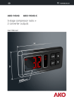
1564H502 Ed.03 GB
PROPlus Basic / CAMCtrl Basic
User Manual
AKO-15645
AKO-15626
AKO-15646
AKO-15627
AKO-15648
Index
Page
1.- Presentation .......................................................................................................3
1.1.- Versions .................................................................................................3
1.2.- Maintenance ..........................................................................................3
1.3.- Cautions ................................................................................................3
2.- Installation..........................................................................................................4
3.- Wiring ................................................................................................................6
3.1.- Pressure switch wiring options ...............................................................9
4.- Recommendations..............................................................................................10
5.- Connectivity .......................................................................................................11
6.- Description ......................................................................................................12
6.1.- Quick access to functions .....................................................................12
6.2.- Messages .............................................................................................13
7.- Wizard..............................................................................................................14
8.- Basic configuration ...........................................................................................15
9.- Operation .........................................................................................................16
9.1.- Compressor control .............................................................................16
9.2.- Defrost control .....................................................................................18
9.3.- Fan control...........................................................................................19
9.4.- Light control.........................................................................................19
9.5.- Pump down function............................................................................20
9.6.- Alarms .................................................................................................21
9.7.- Trapped person alarm...........................................................................22
9.8.- Access code (password)........................................................................22
9.8.- Parameter transfer................................................................................23
9.9.- Other functions ....................................................................................23
9.10.- Program version .................................................................................24
10.- Advanced configuration....................................................................................24
10.1.- Parameters .........................................................................................25
11.- Technical specifications .....................................................................................29
AKO Electromecánica thanks and congratulates you for purchasing our product, in whose development and manufacture the most
innovative technology has been used, as well as strict production and quality control processes.
Our commitment to satisfy our customers and our continuous efforts to improve every day can be seen in the various quality certifications we have obtained.
This is a high performance, high technology product. The operation and final performance of the equipment depend on proper planning, installation, configuration and commissioning. Read this manual carefully before installation, and always follow its instructions.
Only qualified personnel should install or perform technical assistance on this product.
This product is designed to be used in the applications described in the product manual. AKO Electromecánica gives no guarantee
of its operation in any use not foreseen in the manual, and is not responsible for any damage resulting from improper use, configuration, installation or commissioning.
It is the responsibility of the installer and the customer to comply with and ensure others comply with all regulations applicable to
installations incorporating our products. AKO Electromecánica is not responsible for any damage caused by non-compliance with regulations. Follow strictly the instructions given in this manual.
To maximise the service life of our equipment, these recommendations should be followed:
Do not expose electronic equipment to dust, dirt, water, rain, humidity, high temperatures, chemicals or corrosive substances of any sort.
Do not submit the equipment to blows or vibrations nor try to manipulate it differently from shown in the manual.
Never exceed the specifications and limitations indicated in the manual.
Always respect the specified ambient working and storage conditions.
During and after installation, avoid leaving loose, broken, unprotected or damaged wiring, since they might constitute a risk for the equipment and its users.
AKO Electromecánica reserves the right to make any non-metrology modification to the documentation or the equipment without
previous notice.
2
1.- Presentation
PROPlus / CAMCtrl is the global electronic solution to manage positive and negative cold room stores, in
combination with:
ŸStandard condensing units
ŸStreamlined condensing units
ŸOr as a service panel in decentralised systems.
Easy to install thanks to the configuration wizard, it has circuit breaker protection of up to 16A (depending on the
model), a high degree of IP65 protection for installations in damp atmospheres and 2 digital inputs.
1.1.- Versions
MODELS
DESCRIPTION
POWER SUPPLY
AKO-15626
CAMCtrl Basic
AKO-15627
AKO-15645
PROPlus Basic 1F
AKO-15646
230 V ±10%
50 Hz ±5 Hz
AKO-15648 PROPlus Basic 3F
400 V ±10%
50 Hz ±5 Hz
COND. EVAP.
UN.
FAN
230 V/I 230 V/I
DEFROST
230 V/I
400 V/III
CIRCUIT BREAKER
PROTECTION
MODBUS
COMM.
No
11 A
2.500 W
16 A
3A
9A
-
5.500 W
16 A (Power Supply)
10 A / III (Defrost)
Yes
T.P.
ALARM.
No
Yes
No
Yes
No
1.2.- Maintenance
Clean the surface of the unit with a soft cloth, water and detergent. Do not use abrasive detergents, petrol, white
spirits or solvents.
1.3.- Cautions
-Using the unit not observing the manufacturer's instructions may alter the appliance safety requirements. Only
probes supplied by AKO should be used for the unit to operate correctly.
-From -40 ºC to +20 ºC, if the NTC probe is extended to 1000 m with at least 0.5 mm2 cable, the maximum
deviation will be 0.25 ºC (cable for probe extension ref. AKO-15586).
-Only NTC probes supplied by AKO should be used for the appliance to operate correctly.
-Should be installed in a place protected from vibrations, water and corrosive gases, where the ambient
temperature does not exceed the value indicated in the technical data.
-For the reading to be correct, the probe should be used in a place without heat influences apart from the
temperature you want to measure or control.
-Always disconnect the power supply to do the wiring. The power supply circuit should have a main switch and
residual current protection outside the panel (according to 2 2 R.E.B.T.). The power supply cable will be H05VV-F
2x2.5 mm2 or H05V-K 2x2.5 mm2.
-Cables for relay or contactor outputs should have a section of 2.5 mm2, allow working temperatures equal to or
over 70 ºC and be installed with as few bending as possible.
-The length of probe cables and the digital inputs must not exceed 30 metres.
-IP65 protection degree is only valid with the protection cover closed.
-IP65 protection degree is only valid if the cables enter the device using a tube for electric conductions + gland
with IP65 or above. The gland should be the right size for the diameter of the tube used.
IMPORTANT:
ŸThe AUXILIARY relays are programmable, and their operation depends on the configuration (see page 27).
ŸThe function of the digital inputs depends on the configuration (See page. 27).
ŸThe recommended currents and powers are the maximum working currents and powers.
3
2.- Instalation
Panel assembly
(fig. 1)
F
B
A
C
D
M
E
I
G
-Remove the connections cover (D).
-Separate the front (B) from the box (A).
-Choose the most suitable cable entry for the facility (fig. 2).
H
-Make the holes for the glands using the pre-drilled centres as a guide.
-Drill 3 holes on the wall following the box fixing holes (E)
-Fasten the box to wall inserting and tightening 3 screws + plug (F).
-Insert the cables through the glands.
Only AKO-15648
-Connect the defrost resistors to the contactor K1 output (terminals L1 to L4). Next connect the three-phase power
supply cables to F1 circuit breaker and make the connections shown in the connection diagram.
-Position flanges according to figure 5 (next page) and connect the power supply cable (I) to the device's input.
Only AKO-15645 / AKO-15646
-Connect the power supply to the FM circuit breaker as indicated in the wiring diagrams and position the flanges
according to figure 4 (next page). Connect the power supply cable (I) to the device's input.
Only AKO-15626 / AKO-15627
-Connect the power supply (230V AC) to the input of the equipment using the removable terminal as shown in the
connection diagrams.
ALL
-Assemble the front on the box (B) carefully making sure that the cables are not pinched.
-Insert and tighten the two screws on the front (G).
Sólo AKO-15648
-Connect the cables of K1 contactor coil (red cables) to terminals 17 and 18.
ALL
-Connect the rest of the wiring following the diagrams in section 4 and position the flanges according to figure 3 (next
page).
-Join all the grounding connections to the supplied terminal.
-Close the connections cover (D), insert and tighten the fixing screws (H).
4
Fig. 2
Fig. 3
Passage area
for routing the cables
(depending on model).
Fig. 4
Fig. 5
FM
FM
F1
L1
L2
L3
L4
A1
T3
T4
A2
K1
T1
Power supply
input
140
140
5
T2
Pushbutton assembly
The push button should be installed inside the
cold room store, in a visible place and no higher
than 125 cm from the floor.
A
AKO-520622
B
Secure it to the wall through the holes
designed for this purpose (A), connect it to the
device following the wiring diagram and close
the cover using the screws included (B).
A gland is included for cables with a Ø of 6 to
12 mm
A
B
Recommended installation
The cable must make a 180º bend after
exiting from the bottom of the button case (as
seen in image) to prevent water from reaching
cables.
180º
3.- Wiring
Trapped person in cold room store pushbutton (Only AKO-15627 / AKO-15646)
AKO-15627
AKO-15646
1 2 3 4 5 6 7 8 9 P1 P2 P3
Max.
100 mts
10 11 12
13
14
15
16
+12Vcc
PUSHBUTTON
Cable not
included
GND
Bridge necessary
6
17
18
Control panel
* I max. < 15 A
10 11 12
MODBUS
RS-485
13 14 15 16 17 18 19 20 21 22
C
DI1
DI2
9
NO
GND
8
NC
6 7
Tr
5
Tr
3 4
GND
2
S1
1
S2
AKO-15626 / AKO-15627
AUX.
AUX.
AUXILIARY
RELAY 2
2 (2) A
230 V~ *
CRANKASE
HEATER
150 W
POWER SUPPLY
230 V~ *
INPUT
230 V ±10%
50 Hz ±5 Hz
DEFROST
RESISTANCE
2500 W
230 V~*
AUXILIARY
RELAY 1
2 (2) A
230 V~ *
FAN
3 (3) A
230 V~ *
CONDENSING
UNIT
11 (11) A
230 V~ *
JOIN ALL OF THE
EARTH CONNECTIONS
EXTERNALLY
DI2
10 11 12
MODBUS
RS-485
13 14 15 16 17 18 19 20 21 22
C
DI1
9
NO
GND
8
NC
6 7
Tr
5
* I max. < 15 A
Tr
3 4
GND
2
S1
AUX.
DEFROST
RESISTANCE
2500 W
230 V~*
AUXILIARY
RELAY 1
2 (2) A
230 V~ *
AUX.
AUXILIARY
RELAY 2
2 (2) A
230 V~ *
FM
FAN
3 (3) A
230 V~ *
C-16
POWER SUPPLY
INPUT
230 V ±10%
50 Hz ±5 Hz
CONNECT ALL EARTH
CONNECTIONS IN
THIS TERMINAL
PE
1
S2
AKO-15645 / AKO-15646
7
CRANKASE
HEATER
150 W
230 V~ *
CONDENSING
UNIT
11 (11) A
230 V~ *
* I max. < 15 A
10 11 12
MODBUS
RS-485
13 14 15 16 17 18 19 20 21 22
C
DI1
DI2
9
NO
GND
8
NC
6 7
Tr
5
Tr
3 4
GND
2
S1
1
S2
AKO-15648
AUX.
AUXILIARY
RELAY 2
2 (2) A
230 V~ *
AUX.
CRANKASE
HEATER
150 W
230 V~ *
AUXILIARY
RELAY 1
2 (2) A
230 V~ *
FAN
3 (3) A
230 V~ *
FM
C-16
F1
L1
L2
L3
L4
A1
T1
T2
T3
T4
A2
CONDENSING
UNIT
9 (9) A
230 V~ *
K1
C-10
N U V W
NR S T
PE
POWER SUPPLY
INPUT
400 V ±10%
50 Hz ±5 Hz
DEFROST
RESISTANCE
5500 W
400 V~ / III*
PE
CONNECT ALL EARTH
CONNECTIONS IN THIS TERMINAL
ATTENTION: Make sure to turn of the equipment's power supply before handling it, as different
areas may be energised.
IMPORTANTE:
ŸThe recommended currents and powers are the maximum working currents and powers.
ŸThe function of auxiliary relays 1 and 2 can be configured (see page 27).
ŸThe function of the digital inputs depends on the configuration (See page. 27).
8
3.1.- Pressure switch wiring options
Combined High/Low pressure controller
Configuración
Input 1 configuration: P10=6
Input 1 polarity: P12=0
Input 2 configuration: P11=3
Input 2 polarity: P13=0
Aux. relay configuration: P6=2
25 26 27
HP
LP
Separate Low and High pressure controller
Configuración
Input 1 configuration: P10=6
Input 1 polarity: P12=0
Input 2 configuration: P11=3
Input 2 polarity: P13=0
Aux. relay configuration: P6=2
25 26 27
HP
LP
HIGH
LOW
3 terminal High - Low pressure-controller
Configuración
Input 1 configuration: P10=6
Input 1 polarity: P12=1
Aux. relay configuration: P6=2
25 26 27
LP
HP
Pressure controller equivalence
HIGH / LOW
4
5
6
A C B
DANFOS
/ PENN
4
5
6
4
5
6
21 14 12 22 11
1
4
2
ALCO
9
RANCO
4.- Recommendations
Disconnect the voltage before carrying out any operations inside the electrical panel. All wiring should be according to
current standards and should be carried out by authorised staff. Only carry out the wiring foreseen in the wiring
diagrams. Using the electrical panel not observing the manufacturer's instructions may alter the appliance's safety
requirements. A tool is needed to remove any fixed part.
Panel installation:
It is advisable to leave a clean safety space without obstacles around the panel.
Do not knock or make sudden movements on the panel.
Carry out the wiring according to the installation manual.
The probes and their cables should NEVER be installed in a conduit together with power, control or feeder cables.
The earth terminals that the panels contain are installed to guarantee the continuity of earthing, however, earthing is
not carried out by the terminal and should be carried out outside the panel.
The neutral ratings are of the TT type. The IT rating should not be used.
Circuit breakers (protective switches) are of the phase/s + neutral, curve C type, guaranteeing switching and protection
against overcurrents.
Close the panel when your are not working on it.
Residual current protection outside the electrical panel according to low voltage electrotechnical regulations.
The panels meet European standard EN 61439-1.
Terminals for copper external conductors.
Checks before starting the panel up:
Power supply voltages and frequencies will be the ones that figure in the "Technical specifications" section.
Check that there are no loose parts or foreign bodies on connections or switchgear.
Check that there is no dust or damp inside the panel.
Check the correct fastening of the switchgear and components.
Check the correct tightening of the screws and power connections.
Check the correct connection of the power conductors.
Check the correct insulation of the outer lines and that they do not mechanically force the inner connections of the panel.
Before starting the installation up, we recommend preheating the compressor's housing.
Checks during the panel start-up:
Check that no electric arcs occur.
Check that the relays or contactors do not produce ratios.
Check that there is no overheating in cables, controllers and the rest of the switchgear.
Checks after the first 24 hours of operation:
Check that no overheating occurs.
Retighten screws and power connections.
Periodical preventive maintenance:
The panel should remain closed using its lock.
Retighten the power connections once a year.
Check the wear of the switchgear once a year.
Clean the outer surface of the panel with a soft cloth, water and detergent. Do not use abrasive detergents, petrol,
white spirits or solvents.
Technical data:
Working ambient temperature: -5 ºC to 40 ºC
Rated isolation voltage Ui = 440 V~
Electrical panels with degree of protection: IP 65
CEM B environment
Terminals for copper conductors
Resistance to short-circuits Icc=6 kA / 4,5kA
Rated pulse voltage (Vimp) 2,5 KV
Cable isolation voltage:
Operation: 500V (Halogen free)
Power: 750V (Halogen free)
10
5.- Connectivity
The unit has a port for RS485 date connection (MODBUS), which can be managed using a PC.
Up to 127 units can be connected to a PC with AKONet (AKO-5010), or to the AKO-5011 web server. Each of these
units should have a different MODBUS address, that is defined using the P5 parameter of the CnF menu.
Using the AKONet software it is possible to display and capture the data of any connected unit, and configure its
parameters.
AKONet: Management software for AKO units with RS485 (MODBUS) communication. If it is installed in a server the
software can be accessed from any PC in the network or even from Internet (it requires the server having connection to
Internet and fixed IP).
AKO-5011: Web server that includes the AKONet software. It can carry out the same functions as the PC, with the
advantage of having a server dedicated to communication with the units.
AKO-80039
converter
PC with
AKONet
(AKO-5010)
LAN
ó
+
RS-485
Tr+ Tr-
AKO-5011
web server
PROPlus /
CAMCtrl
A-
CAMRegis
AKO-157xx
CAMAlarm
AKO-52063/52064
B+
AB+
GND
Tr- Tr+ Gnd
Tr- Tr+ Gnd
AKO-80024*
repeater
SET
ESC
SET
?
ESC
?
AB+
Tr-
B+
Tr+
GND
GND
TrTr+
GND
Tr- Tr+ Gnd Tr- Tr+ Gnd
Tr- Tr+ Gnd
A-
AKO-14917**
Converter
AKO-146xx
ºC
ºF
13 14 15
AKO-DARWIN
controller with
built-in
communication
Tr- Tr+ Gnd
Red AKO-21904
Black
AKODUO
?
SET
ESC
Grey
*If over 31 units are connected, use an AKO-80024 connector.
11
PROPlus 3PH
AKO-156xx
6.- Description
Temperature
Pushbutton
Stand-by active mode
Only AKO-15627 /
AKO-15646
Change of the Set Point active
(see page 16)
Continuous cycle active
Cold room light active
Alarm active
Defrosting in progress
Fans active
Compressor active*
Compressor or solenoid active**
Only AKO-15648
Display
Browser
Escape key
Light key
Safety cover
Defrosting thermal protector
Circuit breaker
(Only AKO-15645/
AKO-15646)
Manoeuvring thermal protector
* If pump down is active, it indicates the operation of the compressor.
** If pump down is active, it indicates that the solenoid is open, otherwise it indicates that the compressor is in operation.
6.1.- Quick access to functions
SET
SET
ESC
Pressing it for 5 seconds activates or
deactivates the defrost.
If probe 1 is displayed by default, the value
of probe 2 will be displayed by pressing and
vice versa. (see parameter P8)
Pressing it for 5 seconds, the quick setup
menu is accessed.
Silences the alarms (they are indicated on the
display).***
Pressing it for 5 seconds activates or
deactivates the Stand-By mode. The display
shows the m symbol in this mode.
SET
Pressing it for 5 seconds allows changing the
SET POINT temperature.
SET
Pressing it for 5 seconds, activates or deactivates the CONTINUOUS CYCLE.
SET
Pressing it for 10 seconds, the advanced setup
menu is accessed.
¿
SET
*** The trapped person alarm (button AKO-520622) cannot be silenced.
12
Pressing it for 2 seconds, activates or deactivates the cold room light (if P6 or P62=1). This
function stays active although the unit is in the
m mode.
6.2- Messages
Flashing 0: Access code (Password) request
You must enter the access code configured on L5 to execute the requested
function (p. 22).
See also parameter P2 (p. 27)
Probe 1 or 2 faulty
(open circuit, crossover or temperature outside the probe limits; NTC: -50
To 99 ºC).
(Activates alarm relay and sound alarm) *
Indicates a defrost is underway. When the defrost process has finished, the
message will continue to be displayed during the time defined in parameter
d3 (see Chapter 9.2).
Alternating with temperature:
Maximum temperature in control probe alarm. Temperature set in A1 has
been reached (p. 15)
(Activates alarm relay and sound alarm) *
Alternating with temperature:
Minimum temperature in control probe alarm. Temperature set in A2 has
been reached (p. 15).
(Activates alarm relay and sound alarm) *
Alternating with temperature:
External alarm activated (by digital input) (p. 21).
(Activates alarm relay and sound alarm) *
Alternating with temperature:
Severe external alarm activated (by digital input) (p. 21).
(Activates alarm relay and sound alarm) *
Alternating with temperature:
Defrost alarm time-out. Displayed when a defrost ends after the maximum
time elapsed as defined in parameter d1. (p. 21).
(Message only displayed on screen)
Alternating with temperature:
Door open alarm. Shown if the door remains open longer than specified in
parameter A12 (p. 21).
(Activates alarm relay and sound alarm) *
Alternating with temperature:
Pump down malfunction error (Stop) (Page 20).
(Message only displayed on screen)
Alternating with temperature:
Pump down malfunction error (Start up) (Page 20).
(Message only displayed on screen)
Flashing:
Trapped person in cold room store alarm. (Page 22)
(Activates alarm relay and sound alarm) *
* Requires auxiliary alarm 2 to be configured as alarm relay (P62=2)
13
7.- Wizard
The PROPlus Basic and CAMCtrl Basic units have a programming wizard that
configures the equipment depending on the selected control type. The different options
are displayed in the table, the rest of parameters will be configured according to the
“Def” column of the parameter table (See section 10.1).
This wizard only starts the first time the device is powered up, displaying the text P3
on screen.
To restart the wizard after the initial configuration, restart the controller (turning the power supply on and off) and
before 8 seconds have passed, press the following sequence of keys in the indicated order: N , Q y SET.
DEFAULT SETTINGS BY CONTROL TYPE (P3)
P3=1: Service box
P3=2: Pump down active
P6: AUX relay 1 configuration
1: Light
2: Pump down
P62: AUX relay 2 configuration
2: Alarm
1: Light
P10: Digital input 1 configuration
P12: Digital input 1 polarity
0: Off
6: Low pressure switch
0: Energised on closed contact
1: Energised on open contact
WARNING: The default parameters by type of application have been defined for the most common
applications. Check that these parameters are suitable for your installation.
14
8.- Basic configuration
The basic configuration menu allows the equipment to be configured for the most common applications. Press the
SET key for 5 seconds to access it.
If the access code is activated, a 2 digit code is requested (See page 22), if the code entered is not correct the unit
will not enter programming.
If more specific configuration is required use the advanced configuration menu (see page 24)
After 20 seconds without touching any key, the unit returns to the previous level without saving changes or it will
exit programming.
SET
SET
Passes on to the next parameter or increases the
value of the parameter.
Accesses the selected parameter or accepts the
value.
SET
ESC
Passes back to the previous parameter or
decreases the value of the parameter.
Allows exiting a parameter without saving the
changes or exiting programming.
Function of the keys in programming
SP: Set point
It defines the temperature that should be inside the cold storage room (See page 16):
ŸMinimum: –50.0 *
ŸMaximum: 99 *
*(Depends on the bottom/top locking of the set point).
d0: Defrost frequency
Time that must elapse between the starting of each defrost (see page 18)
d1: Maximum defrost duration
The defrost will end after this time has elapsed since it started.
d7: Defrost type
Defines the defrost type to be performed. 0= Resistors
1= Inverted cycle
2= Fan / air orCompressor off
F3: Fan status during defrost
It defines the status of the fans during defrost.
0= OFF
1= ON
A1: Maximum alarm probe 1
Defines the temperature at which the maximum alarm will be triggered. Only affects probe 1.
ŸMinimum: –50.0 *
ŸMaximum: 99 *
*(Depends on the bottom/top locking of the set point).
A2: Minimum alarm probe 1
Defines the temperature at which the minimum alarm will be triggered. Only affects probe 1.
ŸMinimum: –50.0 *
ŸMaximum: 99 *
*(Depends on the bottom/top locking of the set point).
15
9.- Operation
9.1.- Compressor control
ducts.
probe 1 reaches the set
ws
the % differential
icon while this
mode is active.
probe's
(C1),
ates and makes the
he set point value (SP) is
ops.
NORMAL OPERATION
When the temperature in probe 1 reaches the set
point value (SP) plus the probe's differential (C1),
the compressor activates and makes the
temperature drop. When the set point value (SP) is
reached, the compressor stops.
ON
COMP.
OFF
ºC
SP
SP+Dif.
CONTINUOUS CYCLE MODE
Use this function to cool the cold rooms before loading products.
It is activate pressing the O key for 5 seconds, the display shows the % icon while this mode is active.
ON
COMP.
OFF
Upon enabling this mode, the compressor starts up
until the temperature of probe 1 reaches the set
point value, minus the change indicated in parameter C10.
The unit will then return to normal operation.
If this point is not reached, the unit returns to normal operation after the
time set in C9, or by pressing the O key again for 5 seconds.
efrigeration device. If this variation is positive (in
C9
SP
SP+C1
ºC
s.
e % icon while this mode is active.
“CHANGE OF SET POINT” FUNCTION
Modifies the set point value in the low-use periods of the refrigeration device. If this variation is positive (increases
the value), the display will show the ECO icon.
ON
Operation is the same as in the normal ode, but
increasing the set point the amount of degrees
defined in the C12 parameter.
COMP.
OFF
ºC
SP+C12 (SP+C12)+C1
It can be activated after a certain time has elapsed (defined in parameter C11) without activity in the cold room
door, to do this one of the digital inputs such as “door contact” (P10 or P11 = 1) must be configured.
Optionally, you can activate and deactivate this mode at will, using an external pushbutton (1 press to
activate/deactivate), configuring one of the digital inputs as “Change set point” (P10 or P11 = 4).
If we set parameter C11 to 0, it can only be activated by external pushbutton.
efrigeration device. If this variation is positive (in
ed in parameter C11) without activity in the col
act” (P10 or P11 = 1) must be configured.
at will, using an external pushbutton (1 p
“Change set point” (P10 or P11 = 4).
16
COMPRESSOR PROTECTION DELAY
There are three types of delay, selectable by parameter C4, to protect the compressor. These delays prevent
continuous compressor starts and stops due to sudden changes in temperature.
OFF-ON (C4=0): Minimum compressor OFF time before each start-up.
OFF-ON / ON-OFF (C4=1): Minimum time during which the compressor will remain ON and OFF in every cycle.
The delay time is defined by parameter C5.
OFF-ON (C4=0)
OFF-ON / ON-OFF (C4=1)
ON
ON
COMP.
OFF
Time
COMP.
SP
OFF
SP+C1
C5
SP
C5
Time
SP+C1
C5
OPERATION IN CASE OF PROBE 1 FAILURE
In the event of probe 1 failure (fault, disconnection, etc.) compressor performance will depend on C6 settings.
Users may choose between 3 options:
C6=0: The compressor will be stopped until probe 1 is working again.
C6=1: The compressor will be operational until probe 1 is working again.
C6=2: The compressor will operate according to the average performance of the last 24 hours, taking into
account the number of starts and stops and the average time in each state (stop-start).
C6=3: The compressor will run as scheduled in C7 (ON) and C8 (OFF).
Probe 1 error (If C6=3)
ON
COMP.
OFF
C7
C8
C7
C8
Time
SET POINT LOCKING
Using the C2 and C3 parameters, it is possible to set an upper and a lower limit for the Set point (SP), which
precludes configuring a set point that is too low or too high that could damage the installation or the stored
product.
STOP FANS AND COMPRESSOR WHEN THE DOOR IS OPENED
Parameter P23 defines whether the compressor stops when the cold room door is opened. To do so one of the
digital inputs must be configured as "door contact" (P10 or P11=1) (See page 27).
If the door stays open longer than the value programmed in parameter P24, the compressor will return to its
normal operation.
17
9.2.- Defrost control
Max. d1
F4
d3
FAN START DELAY
CONTROL
DEFROST
“DEF” MESSAGE
DRIP
TIME
CONTROL
DEFROST
d9
ºC
d0
d4
SP+C1
SP
time
Defrost start-up
Defrost is initiated if:
-Time scheduled in parameter d0 has passed since the beginning of last defrost.
-The N key is pressed for 5 seconds.
Defrost type
Selected by parameter d7 to define the controller performance during the defrost process.
By air / compressor shutdown
(d7=2)
The compressor stops and the defrost takes place statically.
Fans will be running or not depending on parameter F3.
By resistors
(d7=0)
The defrost resistors start up and the compressor stops; defrost is the result of heat from
the resistors.
Fans will be running or not depending on parameter F3.
Reverse cycle (Heatpump)
(d7=1)
A 4-way valve is activated which reverses the cold-generating circuit and the compressor
starts up, forcing the defrost.
Fans will be running or not depending on parameter F3.
Drip time
Parameter d9 sets drip time and the time added at the end of defrost cycle to allow for drainage of the remaining
water in the evaporator. During this time the compressor and fans will not be running (unless defrost is by air).
Defrost termination
The defrost will terminate if:
-The temperature programmed in parameter d4 has been reached in probe 2 (Requires a 2nd probe to be
available and for it to be activated using parameter P4).
-Time set in parameter d1 has passed (maximum duration of defrost).
-The H key is pressed for 5 seconds.
Message displayed during defrost
Set by parameter d2, with the choice of showing the actual temperature detected by probe 1 (d2=0), displaying
the temperature detected by probe 1 at the start of defrost (d2=1) or displaying the DEF message (d2=2). The d3
parameter defines the time during which the message is displayed, once the drip time (d9) and the fan stop time
(F4) is over.
18
al button, connecting it to one of the digital inputs
Other parameters
Parameter d5 allows users to specify if the unit will (d5=1) or will not (d5=0) defrost when powered up (initial
start-up or after a power failure). In case of choosing option YES (d5=1), the defrost will start after the delay time
specified in d6.
Using parameter d8, users define the computation of time in d0, choosing between total time elapsed (d8=0) or
the total compressor running time (d8=1).
F0 (shutdown temperature) and F1 (Probe differen
the probe (E2), the fans will always run regardl
2 to F5.
9.3.- Fan control
or stops.
NOTE: If parameter d1 is set to 0, no defrost will be performed.
Remote defrost
This function allows activating the defrost of the unit using an external button, connecting it to one of the digital inputs
that must be configured as "remote defrost”(P10 ó P11=7) .
Fan control
ON
COMP.
OFF
ON
Only if F2=1
FAN
OFF
e section 9.2)
Time
F0
(probe 2)
F0+F1
probe 2)
SP
SP+C1
Fans are controlled with probe 2 (evaporator) and parameters F0 (shutdown temperature) and F1 (Probe differential).
Even if probe 2 is not connected or an error is detected in the probe (E2), the fans will always run regardless of
parameters F0 and F1, but taking into account parameters F2 to F5.
Parameter F2 defines the status of the fans during compressor stops.
Parameter F3 defines the status of fans during defrost.
Parameter F4 defines the fan start-up delay after defrost (see section 9.2)
9.4.- Light control
P62=1).
Auxiliary relay 1 or 2 must be configured as “Light” (P6 or P62=1).
Switching the lights on or off is controlled using:
ŸThe ? pushbutton: One press switches the lights on or off.
ŸThe cold room door: When the door is opened, the lights stay on for the time
n or off.
utdown
andtime
F1 (Probe differential).
he
lightstemperature)
stay on for the
obe
(E2), closes
the fans
always
run regardless
the door
thewill
lights
go out.
(One of theofd
5.
P11=1).
s.
defined by parameter P22. If the value is 0, when the door closes the lights go out. (One of the digital
inputs must be configured as door contact (P10 or P11=1).
The control even occurs with the equipment in Stand-by.
19
9.5.- Pump down function
This function prevents compressor problems caused by movement of the refrigerant, using a stop/start technique of
the unit controlled by liquid solenoid, the low pressure switch and the compressor.
For this feature to be active, the auxiliary relay must be set as "Pump down" (P6=4), which automatically
configures digital input 1 as "low pressure switch" (P10=7)
SHUTOFF
When temperature probe 1 reaches the set point value (SP), the AUX 1 relay is deactivated by closing the liquid
solenoid.
Since the compressor is still running the evaporator pressure drops suddenly. When it reaches a specific point, the
low pressure switch is activated, changing the state of digital input 1, and the controller stops the compressor.
This manoeuvre isolates the refrigerant from the compressor crankcase, preventing serious damage on start-up.
In case of low pressure switch failure, the controller stops the compressor after the safety time set at P15, showing
the message "Pd", but it will continue to function normally. (informative message, does not affect the equipment
operation).
If time P15 is 0 (default value), the compressor will not stop until the low pressostat is activated, but it will display
the “Pd” message after 15 minutes.
STARTUP
When temperature probe 1 reaches the set point value plus the differential (SP+C1), the AUX 1 relay is activated
(ON), opening the liquid solenoid. This causes the pressure in the evaporator to increase, disabling the low pressure
switch. The controller detects this change and starts the compressor.
If a period of time has elapsed (determined by P14) after the liquid solenoid is opened (AUX 1 relay set to ON), the
low pressostat will not be deactivated, the controller will once again close the solenoid (AUX 1 relay set to OFF)
and the “LP” message will be displayed. This manoeuvre will be repeated every 2 minutes indefinitely until the
pressostat is deactivated and the installation reverts to its normal operation.
If time P14 is 0 (default value), the solenoid will stay open until the low pressostat is deactivated, but it will display
the “LP” message after 3 minutes.
STAND-BY
If the pump-down function is active, some time may elapse from the time the stand-by function starts until the
controller stops. This is because certain control phases of the system cannot be stopped.
Liquid
solenoid
ON
AUX 1
OFF
Low pressure Digital
Input
switch
Pressure
switch fault
Pressure
switch fault
ON
OFF
ON
Compressor
COMP.
OFF
Evaporator
pressure
+
P15
Time
SP
SP+C1
20
SP
P14
SP+C1
9.6.- Alarms
The unit warns the user with a message on the screen of the activation of a relay or the activation of an acoustic signal in
certain circumstances, according to the programming of the following parameters.
Max/Min Temperature Alarm
Shows the AH or AL message when the temperature in probe 1 reaches the value set in
the A1 (maximum temperature) and A2 (low temperature) parameters.
This value can be:
Absolute (A0=1): A1/A2 should indicate the temperature at which the alarm should
be activated.
Relative to SP (A0=0): A1/A2 should indicate the number of degrees above or
below the set point at which the alarm is activated. This
option allows users to adjust the set point without having to
modify the high and low alarm settings.
Parameter A10 sets the differentials for both parameters (hysteresis).
Activates alarm relay (if P62=2) and sound alarm.
Example
In a controller we configure the following parameters: SP=2, A1=10, A10=2
- If A0=0 (relative to SP), the maximum temperature alarm goes off when probe 1 reaches 12 degrees
and is disabled when it reaches 10 degrees.
- If A0=1 (absolute), the maximum temperature alarm goes off when probe 1 reaches 10 degrees and is
disabled when it reaches 8 degrees.
External alarm/severe external alarm
Displays the message AE (external alarm) or AES (severe external alarm), when the digital
input configured as external alarm or severe external alarm is activated.
The severe external alarm also deactivates all the charges, therefore, the temperature regulation
is stopped. When this alarm disappears the device returns to its normal operation.
At least one of the digital inputs must be configured as external alarm (P10 or P11=2) or
severe external alarm (P10 or P11=3).
Activates alarm relay (if P62=2) and sound alarm.
Defrost alarm completed by time.
Shows the Adt alarm message when a defrost terminates by time-out, if parameter A8=1.
DOES NOT activate the alarm relay or the sound alarm, it is only shown on the display.
Door open alarm
Displays the PAb message when the door stays open for a time greater than that set with parameter A12. (One of
the digital inputs must be configured as door contact (P10 or P11=1).
Activates alarm relay (if P62=2) and sound alarm.
Pump down malfunction error (Stop)
Displays the Pd message if a malfunction is detected when the installation is stopped
using the pump down manoeuvre. (See page 20).
DOES NOT activate the alarm relay or the sound alarm, it is only shown on the display.
Pump down malfunction error (Start up)
Displays the LP message if a malfunction is detected when the installation is started up
using the pump down manoeuvre. (See page 20).
DOES NOT activate the alarm relay or the sound alarm, it is only shown on the display.
21
Alarm delay
These delays prevent the display of specific alarms while allowing the unit to recover normal operation after certain
events.
-Start-up delays (A3): Delays activation of temperature alarms on power-up (start-up or after a power failure).
This allows avoiding continuous alarms upon start-up
-Delay after defrost (A4): Delays activation of temperature alarms post-defrost.
-Delay of max/min temperature alarm (A5): Delays activation of maximum (A1) and minimum (A2) temperature
alarms from the moment temperature probe 1 reaches the set value.
-Delay of external alarm activation (A6): Delays the activation of the external alarm from the moment the digital
input becomes active.
-Delay of external alarm deactivation (A7): Delays the deactivation of the external alarm from the moment the
digital input becomes inactive.
-Door opening alarm relay (A12): Delays activation of the open door opening detection alarm.
Alarm relay configuration
If the auxiliary relay 2 is configured as an alarm relay (P62=2), parameter A9 allows defining the status of the relay
when an alarm is triggered.
ŸA9=0 relay active (ON) in case of alarm (no alarm OFF)
ŸA9=1 Inactive relay (OFF) in case of alarm (no alarm ON)
9.7.- Trapped person alarm
When the trapped person button is activated, the message tPA (trapped person alarm) is displayed on the screen,
the alarm relay (If P62=2) and the sound alarm are activated. This alarm cannot be silenced, to deactivate it you
have to put the button back in its initial position, turning it ¼ of a turn clockwise.
9.8.- Access code (password)
It allows protecting the configuration of the unit using a 2 digit code (from 01 to 99). If it is active a code is requested
when you try to access the programming menu. This menu cannot be accessed if a wrong value is entered. The code is
defined using the L5 parameter.
Parameter P2 defines the operation of this code.
22
9.9.- Parameter transfer
This function allows transferring the programmed parameters of a device to others, using the AKO-D14918
programming key. This will save a lot of time when configuring similar devices. (Not available in AKO-15627 and
AKO-15646)
Connect the key to the equipment as shown in the diagram bearing in mind that:
Power supply
ŸIf the controller is in operation (on-site programming), the key does not require an external power supply (it
is powered via the connecting cable).
ŸIf the controller is NOT powered (workshop programming), the key requires a 12 Vdc/500 mA external
power supply (AKO-80018 or equivalent).
Transfer parameters from the equipment to the key
Press the READ key until the COM led starts flashing quickly. When recording is complete the controller will reset.
Transfer parameters from the key to the equipment
Press the SAVE key until the COM led starts flashing quickly. When recording is complete the controller will reset.
CONNECTOR CABLE
LED COM
READ
KEY
RECORD
KEY
SET
ESC
¿
LED ON
EXTERNAL POWER
CONNECTOR
IMPORTANT: Never disconnect the programming key during data transmission.
9.10.- Other functions
C0: Calibration of Probe 1
It allows correcting the temperature detected by probe 1, this is particularly useful when the probe cannot be
located in the ideal place.
P4: Connected sensors
Choose the correct option according to the no. of probes connected:
Ÿ1= Probe 1: If it has just one control probe. Defrost will end by time.
Ÿ2= Probe 1 and 2: If it has two probes, a control probe and another one for defrost (evaporator).
P8: Sensors to be displayed
It defines which probe will be displayed on the screen.
Ÿ0= All probes sequentially
Ÿ1= Probe 1
Ÿ2= Probe 2
In the sequential mode the screen will display the name of each probe followed by the temperature of each.
(S1 - 8,3ºC - S2 - 6,2ºC)
23
P7: Display mode
It defines the information displayed on the screen during normal operation:
Ÿ0=Integers in ºC
Ÿ1=One decimal in ºC
Ÿ2=Integers in ºF
Ÿ3=One decimal in ºF
P1: Delay at Start-up
They allow delaying the start up of the installation when it receives electricity. This parameter prevents continuous
stoppages and start-ups of the installation in exceptional situations, for example, after a power cut, in test periods
or during the commissioning of the installation. This is established in minutes.
P12 / P13: Polarity of digital inputs 1 and 2
Define whether the input will become active (P12/13=0) on closing contact or on opening it (P12/13=1).
9.10.- Program version
Parameters PU and PR of the tid menu allow for displaying the version and review of the firmware installed in the
equipment.
Use this information if you have to ask for advice from the technical assistance service.
10.- Advanced configuration
Using the advanced configuration menu, you can set ALL the equipment's parameters.
The parameters are grouped into 6 sections depending on their function. Press the N + Q keys for 10 seconds to
access it.
If the access code is activated, a 2 digit code is requested (See page 22), if the code entered is incorrect the unit
will not enter programming mode.
To see the complete parameters list, refer to page 25.
After 20 seconds with no key being pressed, the equipment will return to the previous level. If you are on level 3,
the changes will not be saved.
Advanced configuration
OUT OF
PROGRAMMING
20 sec.
OK
Level 2
Parameters
OK
SET
SET
ESC
ESC
10 sec.
Change
value
Change
parameters
Change
menu
Level 3
Values
OK
SET
ESC
20 sec.
OK
OK
SET
SET
24
Don’t save changes
Level 1
Menus
Save changes
Temperature
Indication
PROGRAMMING
20 sec.
10.1.- Parameters
The parameters are grouped into 6 sections depending on their function. Press the N + Q keys for 10 seconds to
access it.
The def. column shows factory-set default parameters. Those marked with an * are variable depending on the
application chosen in the wizard (see section 7).
Temperature values are expressed in ºC. (Equivalent temperature in ºF)
Level 2
Level 1.- REGULATION AND CONTROL
Units
Min
Def
SP Temperature Adjustment (Set Point) (Pág. 15 y 16)
Description
(ºC/ºF)
-50
0.0
Max.
99
C0 Calibrating probe 1 (Offset) (Pág. 23)
(ºC/ºF)
-20.0
0.0
20.0
C1 Probe 1 differential (Histeresis) (Histéresis) (Pág. 16)
(ºC/ºF)
0.1
2.0
20.0
C2
Upper blocking of the set point (Page 17)
(cannot be set above this value)
(ºC/ºF)
C3
99
99
C3
Lower blocking of the set point (Page 17)
(cannot be set below this value)
(ºC/ºF)
-50
-50
C2
0
0
1
0
0
120
0
2
3
Type of delay for protection of the compressor (Page 17)
C4 0=OFF/ON (since the last disconnection);
1=OFF-ON/ON-OFF (since the last shut-down /start-up)
C5
Protection delay time
(value of the option selected in parameter C4) (Page17)
(min.)
Status of COMP. relay with probe fault (Page 17):
C6 0=OFF; 1=ON; 2=Average based on last 24 hours prior to probe fault;
3=ON-OFF as prog. C7 and C8
C7
Time relay ON in case of faulty probe (Page 17):
(If C7=0 and C8¹0, the relay will always be OFF deenergised)
(min.)
0
10
120
C8
Time relay OFF in case of fault of probe 1 (Page 17):
(If C8=0 y C7¹0, the relay will always be ON energised)
(min.)
0
5
120
C9
Maximum duration of the continuous cycle mode.
(0=disabled) (Page. 16)
(h.)
0
1
48
Variation of the set point (SP) in continuous cycle mode, when it reaches this point
C10 (SP+C10), it reverts to the normal mode. (Page 16) (SP+C10 ³ C3)
(0=OFF) The value of this parameter is always negative, except if it is 0
(ºC/ºF)
0
-50
C3-SP
C11
Idle time of the digital input for the change Set Point function to be activated
(Only if P10 or P11 =1) (0=OFF) (Page 16)
(h.)
0
0
24
C12
Variation of the set point (SP) when the change set point function is active.
(SP+C12 £ C2) (0= disabled) (Page 16)
(ºC/ºF)
C3-SP
0,0
C2-SP
EP Exit to Level 1
25
Level 2
Level 1.- Defrost Control
Description
d0 Defrost frequency (Time between two starts) (Page 15 y 18)
d1 Maximum defrost duration (0=defrost deactivated) (Page 15 y 18)
d2
Units
Min
Def
(h.)
0
6
96
(min.)
0
15
255
0
2
2
0
5
255
-50
8.0
99,0
0
0
1
0
0
255
0
0
2
0
0
1
(min.)
0
1
255
Type of message during defrost: (Page 18)
0=Current temperature; 1=Temperature at start of defrost; 2=Display dEF message
Maximum duration of message
(Time added at the end of the defrost process) (Page18)
(min.)
d4 Defrost end temperature (probe 2) (If P4 ¹ 1) (Page. 18)
(ºC/ºF)
d3
Defrost on equipment start-up (Page19):
d5 0=NO, First defrost as per d0
1=YES, First defrost as per d6
d6 Defrost start delay on equipment start-up (Page 19)
Defrost type:
d7
(Page 15 and 18)
0=Resistors,
2=Fan / air / Compressor off
d8
Calculated time between defrost period (Page 19):
0=Total actual time; 1 =Sum of times the compressor is on
d9
Drip time at end of defrost (Page 18)
(compressor and fans off) (if P4 ¹ 1)
(min.)
1=Inverted cycle,
Max.
EP Exit Level 1
Level 2
Level 1.- Fan control
Units
Min
Def
Max.
Fan shut-down temperature as per probe 2
F0
(if P4 ¹ 1) (Page 19)
Description
(ºC/ºF)
-50
45
99,0
F1 Probe 2 differential (If P4 ¹ 1) (Page19)
(ºC/ºF)
0,1
2,0
20,0
0
1
1
0
0
1
0
3
99
F2 Stop fans when stopping compressor 0=No, 1=Yes (Page 19)
F3
Fan status during defrost: (Page 15 and 19)
0=Off; 1=On
F4
Starting delay after defrost (if F3=0) (Page 19)
Will only operate if it is higher than d9
(min.)
EP Exit Level 1
26
Level 2
Level 1.- Alarm control
Description
A0 Configuration of temperature alarms (Page 21):
Units
0=Relative to SP
1=Absolute
Min
Def
0
1
Max.
1
99,0
A1 Maximum alarm probe 1 (must be greater than SP) (Page 15 and 21)
(ºC/ºF)
A2
99,0
A2 Minimum alarm probe 1 (must be greater than SP) (Page 15 and 21)
(min.)
-50
-50
A1
A3 Temperature alarm delay during start-up (Page 22)
(min.)
0
0
120
A4 Temperature alarm delay after completion of a defrost (Page 22)
(min.)
0
0
99
A5 Temperature alarm delay after reaching the value of A1 or A2 (Page 22)
(min.)
0
30
99
A6 External alarm delay when receiving digital input signal (P10 or P11=2 or 3) (Page 22)
(min.)
0
0
120
Deactivation delay of the external alarm when the signal of the digital input disappears
(P10 or P11=2 or 3) (Page 22)
(min.)
0
0
120
A8 Show warning if defrost is terminated by time-out 0=No, 1=Yes (Page 21)
0
0
1
Alarm relay polarity 0= Relay ON in alarm (OFF no alarm);
A9
(Page 22)
1= Relay OFF on alarm (ON with no alarm)
0
0
1
A7
A10 Temperature Alarm Differential (A1 and A2) (Page 21)
(ºC/ºF)
0,1
1,0
20,0
A12 Door open alarm delay (if P10 or P11=1) (Page 22)
(min.)
0
10
120
Units
Min
Def
Max.
(min.)
0
0
255
Función del código de acceso (password) (Pág. 22)
P2
0= Inactivo; 1= Bloqueo acceso a parámetros; 2= Bloqueo del teclado
0
0
2
P4 Selection of type of inputs (Page 23)
1
1
2
1
1
225
EP Exit Level 1
Level 2
Level 1.- General status
Description
P1 Delay of all functions on receiving electrical power (Page 24)
1=1 probe
2=2 probes
P5 MODBUS address (Page 11)
P6
Configuration of AUX relay 1 (Page 19 and 20) 0=Disabled
1=Light
2=Pump down
3=Equal Compressor state
0
*
3
P62
Configuration of AUX relay 2 (Page 19 and 21) 0=Disabled
1=Light
3=Equal Compressor state
4=Equal state equipment
0
*
4
0
1
3
0
1
2
2=Alarm
Temperature display mode (Page 24)
1=One decimal in ºC
P7 0=Integers in ºC
2=Integers in ºF
3=One decimal in ºF
P8
Probe to be displayed (as per parameter P4) (Page 23)
0=visualization of all the probes in sequence;
1=Probe 1
P10
Configuring digital input 1 (Page 16 to 21)
0= Off
1= Door contact
3= Severe external alarm
4= Change Set Point
6= Low pressure switch
7= Remote defrost
2= External alarm
5= Continuous cycle act.
0
*
7
P11
Configuring digital input 2 (Page 16 to 21)
0= Off
1= Door contact
3= Severe external alarm
4= change Set Point
6= Low pressure switch
7= Remote defrost
2= External alarm
5= Continuous cycle act.
0
0
7
2=Probe 2
27
Level 2
Min
Def
Max.
Digital input polarity 1 (Page 24)
P12
0=Energised on closed contact, 1=Energised on open contact
Description
0
*
1
P13
Digital input polarity 2 (Page 24)
0=Energised on closed contact, 1=Energised on open contact
0
0
1
P14
Maximum start-up time after pump down (Page 20)
(Values between 1 and 9 seconds are not accepted) (0=Disabled)
(seg.)
0
0
120
P15 Maximum pump down time (Page 20) (0=Disabled)
(min.)
0
0
15
P22 Cold room light timer (Page 19)
(min.)
0
0
999
P23 Stop fans and compressor on opening door (Page 17)
Units
0=No
0
0
1
(min.)
0
0
999
Units
Min
Def
Max.
0
0
99
1=Si
P24 Start up delay for fans and compressor with door open (Page 17)
EP Exit Level 1
Level 2
Level 1.- Access control and information (tid)
Description
L5 Access code (Password) (Pág 22)
PU Program version (Information)
-
Pr Program revision (Information)
-
EP Exit Level 1
28
11.- Technical specifications
Power supply AKO-15645 / AKO-15646 /AKO-15626 / AKO-15627 . . . . . . . . . . . . . . . . . . . 230 V~ ±10 % 50 Hz ±5 %
AKO-15648 . . . . . . . . . . . . . . . . . . . . . . . . . . . . . . . . . . . . . . . . . . . . . . . . . . . 400 V~ ±10 % 50 Hz ±5 %
Total maximum current . . . . . . . . . . . . . . . . . . . . . . . . . . . . . . . . . . . . . . . . . . . . . . . . . . . . . . . . . . . . . . . 15 A (Page 7, 8)
AKO-15645 / AKO-15646 /AKO-15626 / AKO-15627 . . . . . . 11 (11) A to 230V~ SPDT
COMPRESSOR relay (20 A)
AKO-15648 . . . . . . . . . . . . . . . . . . . . . . . . . . . . . . . . . . . . . . . . 9 (9) A to 230V~ SPDT
AUX 1 relay (16 A) . . . . . . . . . . . . . . . . . . . . . . . . . . . . . . . . . . . . . . . . . . . . . . . . . . . . . . . . . . . . . . 2 (2) A to 230V~ SPST
AUX 2 relay (8 A) . . . . . . . . . . . . . . . . . . . . . . . . . . . . . . . . . . . . . . . . . . . . . . . . . . . . . . . . . . . . . . 2 (2) A to 230V~ SPDT
FAN relay (16 A) . . . . . . . . . . . . . . . . . . . . . . . . . . . . . . . . . . . . . . . . . . . . . . . . . . . . . . . . . . . . . . . 3 (3) A to 230V~ SPST
DEFROST relay (16 A) . . . . . . . . . . . . . . . . . . . . . . . . . . . . . . . . . . . . . . . . . . . . . . . . . . . . . . . . . . . . 10 A to 230V~ SPST
Probe temperature range . . . . . . . . . . . . . . . . . . . . . . . . . . . . . . . . . . . . . . . . . . . . . . . . . . . . . . . . . . . -50.0 ºC to 99.9 ºC
Resolution, setting and differential. . . . . . . . . . . . . . . . . . . . . . . . . . . . . . . . . . . . . . . . . . . . . . . . . . . . . . . . . . . . . . 0.1 ºC
Thermometric precision. . . . . . . . . . . . . . . . . . . . . . . . . . . . . . . . . . . . . . . . . . . . . . . . . . . . . . . . . . . . . . . . . . . . . . ± 1 ºC
Tolerance of the NTC probe at 25 ºC . . . . . . . . . . . . . . . . . . . . . . . . . . . . . . . . . . . . . . . . . . . . . . . . . . . . . . . . . . . ± 0.4 ºC
Input for NTC probe . . . . . . . . . . . . . . . . . . . . . . . . . . . . . . . . . . . . . . . . . . . . . . . . . . . . . . . . . . . . . . . . . . . . AKO-14901
Maximum input power in the operation. . . . . . . . . . . . . . . . . . . . . . . . . . . . . . . . . . . . . . . . . . . . . . . . . . . . . . . . . . . 10 VA
Working ambient temperature of the panel . . . . . . . . . . . . . . . . . . . . . . . . . . . . . . . . . . . . . . . . . . . . . . . . . . -5 ºC to 40 ºC
Working ambient temperature of the pushbutton AKO-520622 . . . . . . . . . . . . . . . . . . . . . . . . . . . . -20 ºC to 70 ºC
Storage ambient temperature of the panel . . . . . . . . . . . . . . . . . . . . . . . . . . . . . . . . . . . . . . . . . . . . . . . . . . -30 ºC to 60 ºC
Storage ambient temperature of the pushbutton AKO-520622 . . . . . . . . . . . . . . . . . . . . . . . . . . . . -20 ºC to 70 ºC
Overvoltage category . . . . . . . . . . . . . . . . . . . . . . . . . . . . . . . . . . . . . . . . . . . . . . . . . . . . . . . . . . . . . . . . II s/ EN 61439-1
Pollution degree. . . . . . . . . . . . . . . . . . . . . . . . . . . . . . . . . . . . . . . . . . . . . . . . . . . . . . . . . . . . . . . . . . . . II s/ EN 61439-1
Protection degree of the panel. . . . . . . . . . . . . . . . . . . . . . . . . . . . . . . . . . . . . . . . . . . . . . . . . . . . . . . . . . . . IP65 (Page 3)
Protection degree of the pushbutton AKO-520622 . . . . . . . . . . . . . . . . . . . . . . . . . . . . . . . . . . . . . . . . . . . . IP 65
Dimensions . . . . . . . . . . . . . . . . . . . . . . . . . . . . . . . . . . . . . . . . . . . . . . . . . . . . . . . . . . . . . 230(An) x 230(Al) x 95(P) mm
Double isolation between power supply, secondary circuit and relay output.
Type of assembly . . . . . . . . . . . . . . . . . . . . . . . . . . . . . . . . . . . . . . . . . . . . . . . . . . . . . . . . . . . . . . . . . . . . . Fixed internal
Internal buzzer
Encapsulated assembly
29
30
31
We reserve the right to supply materials slightly different to those described in our Data Sheets. Updated information in our web site.
351564502 REV.02 2014
AKO ELECTROMECÁNICA, S.A.L.
Av. Roquetes, 30-38 | 08812 Sant Pere de Ribes | Barcelona | España
Tel. (34) 938 142 700 | Fax (34) 938 934 054 | e-mail: [email protected] | www.ako.com