1
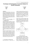
US006243035B1
(12) United States Patent
(16) Patent N6.=
Walter et al.
(45) Date of Patent:
(54)
KEY MODULE FOR WIRELESS KEYBOARD
(75)
Inventors: Ronald J. Walter, Anaheim; John D.
Dent Claremont both of CA (Us)
’
'
.
4,549,179
4,626,847
4,939,514
5,329,370
’
-
-
(73) Asslgnee' lclglvlejrssal Electmmcs Inc" Cypress’
(*)
patent is extended or adjusted under 35
* 10/1985 Stendardo ..................... .. 340/825.69
* 12/1986 Zato
340/825.56
* 7/1990 Miyalakl ----- ~~ 341/22
* 7/1994 YaZolino ..
.. 548/734
5,602,597 *
2/1997 Bertram
5,774,063
6/1998
*
Berry
..... ..
348/565
340/82569
345/327
5,850,340 * 12/1998 York
.. 364/188
5,865,546
2/1999 Ganthier ............................. .. 400/489
*
.
* Cited b examiner
U.S.C. 154(b) by0 days.
y
(21) APPL NO; 09/032,734
Primary Examiner—Michael Horabik
_
Assistant Examiner—Albert K. Wong
(22) F1169?
Feb- 27! 1998
(74) Attorney, Agent, or Firm—Mark R. Galis; John E.
(51)
Int. c1.7 ................................................... .. G08C 19/12
Hyatt
(52)
US. Cl.
(57)
(58)
Jun. 5, 2001
5,844,552 * 12/1998 Gaughan ..
( )
Subject to any disclaimer, the term of this
Notice:
US 6,243,035 B1
.. 341/176; 341/173; 341/20;
341/22
Field Of Search ................................... .. 341/173, 176,
341/20, 22; 345/327; 340/82556, 82569;
348/466, 565; 364/188
ABSTRACT
A Self-Contained module including ?nger depressible keys,
said module being mountable on, and useable With, a
Wireless keyboard for a computer. The module includes a
pre-programmed microcontroller for controlling basic func
( 56 )
'
'
dVCR via
' an IRLED ont h e
tions
0 fh
t e TV an d an associate
References Cited
keyboard.
U.S. PATENT DOCUMENTS
3,940,758 *
2/1976 Margolin .............................. .. 341/22
(23
21
(4
£1
DUDE
BEBE
K1a
KEYBOARD
15 Claims, 5 Drawing Sheets
U.S. Patent
Jun. 5, 2001
Sheet 1 015
W
19
US 6,243,035 B1
9
W W
11 1501 1%
g
‘ 1g
‘
MG. 1
19
N
I
I
ALL
I
l
l
l
l
l
I
I
If
1
I
l
l
I
11/
MG, 2
f
23
21
f 0
I)
USED
BEIGE
K18
KEYBOARD
25')
\
\15
FIG. 3
12
U.S. Patent
Jun. 5, 2001
Sheet 2 0f5
US 6,243,035 B1
21A /2
3 a l
21
\
D
DUDE
T N
GEEK]
K1a
KEYBOARD
\
K15
FIG. 4
U.S. Patent
Jun. 5, 2001
Sheet 3 of5
US 6,243,035 B1
KEY
DIGIT
UEI
0
sET MODE:
PTVIR
A
TV OR VCR
VCR
3
I
CH UP
4
CH DN
VOL UP
VOL DN
MUTE
SCAN
5
6
7
a
9
DOUBLE BLINK
VISIBLE LED
ATE KSYE YDS°
A
.
FIG. 6
ACCUMULATE
KEYPRESSES
SET CURRENT
DEVICE TYPE To
CODE ENTERED
SINGLE LONG
I
DOUBLE BLINK
VISABLE LED
BLINK ON
VISABLE LED
L
(EXIT
T0 NORMAL OPERATION,
WAIT FOR NEXT KEYPRESS
FIG. 7
U.S. Patent
Jun. 5, 2001
Sheet 4 0f5
US 6,243,035 B1
KEYPRESSED
N .
CANCEL
SCAN
UEI KEY? Y X > P
TIRVB
N
\N
S
WU\W / 3E D7.S
ESS|ANnEF_PWM.DINW$V|DP
Y VI
>
MRWEDE“PMWANvim.R AlWf-Huf
R
START SENDING
CH UP AT 3
SEC. TNTERVALS
OUTPUT STANDARD
IR FUNCTION
ACCORDING TO
MODE SELECTED
EXIT, WAIT FOR
NEXT KEYPRESS
FIGS
US 6,243,035 B1
1
2
KEY MODULE FOR WIRELESS KEYBOARD
FIG. 3 depicts a minimally modi?ed standard keyboard in
Which the module is mounted;
FIG. 4 depicts another modi?ed keyboard in Which the
module may be mounted;
FIG. 5 depicts a modi?cation of the module housing for
BACKGROUND OF THE INVENTION
One of the interesting technologies presently being devel
oped is focused on combining the Internet or World Wide
Web With the standard television set, video cassette recorder
(“VCR”) and other home and office electronic products.
mounting on a keyboard With an essentially unmodi?ed
Surveys shoW that almost 90% of US. homes have televi
housing;
sion sets, and most homes have more than one set. Various
FIG. 6 is a listing of the key interpretation during digit
entry;
companies have developed and are selling products to create
Internet sites that are fully compatible With the technology;
10
FIG. 7 is a How chart shoWing the functional overvieW of
these sites Will alloW customers full access to the Internet via
the module;
their television set. It has been observed that the challenge
to universal acceptance of the World Wide Web is, in fact,
the television set (TV).
To utiliZe the emerging Web-to-TV technology, standard
computer keyboards having Wires have been used. Key
boards have long been popular as PC (personal computer)
accessories such as for this application. Companies Which
offer Internet access, using the user’s TV as the display
device, usually offer either corded or cordless keyboards. A
FIG. 8 is a How chart of the device code set-up function
15
of the module; and
FIG. 9 shoWs the electronic circuitry of the module
including the microcontroller.
20
FIG. 1 is a top vieW of the inventive key module 11 that
includes a pre-programmed microcontroller containing a
DESCRIPTION OF THE INVENTION
user can use the keyboard for various Internet functions
universal TV and VCR library, together With a key pad,
generally labeled as 16, and all necessary support circuitry.
It should be understood that although this particular embodi
including the sending of e-mail (electronic mail). HoWever,
for a variety of reasons, infrared (IR) Wireless keyboards
Which have a range of up to 30 feet appear to be the preferred
structure for interfacing With a home TV. Thus, a user merely
25
needs a Wireless keyboard, the TV, a phone line, and the
Internet access service or Internet terminal to conveniently
utiliZe this neW technology. It has been found that a desirable
feature for the user of a cordless keyboard is to be able to
turn on his TV, VCR or cable box, make adjustments to the
ment controls TV and VCR, other devices may also be
included in other versions, e.g. TV and cable or even TV,
VCR and cable, etc. The modular mechanical package is
approximately 5.5 inches in length and 0.5 inches in Width.
30
Module 11 is mountable on a standard computer type
keyboard 15 With a base or housing 17. FIG. 3 is an outline
of a modi?ed standard keyboard plastic housing 17 for the
volume, and make adjustments to other functions thereof,
directly from the keyboard Without having to set the key
board doWn and pick up the TV remote control.
keyboard 15, shoWing keys 18 mounted in respective
Presently, in order for a keyboard manufacturer to offer
shoWn. In a ?rst embodiment of the invention, the mold (not
recesses 21, as is Well knoWn. For purpose of clarity in the
draWing, only a feW of the keyboard keys 18 are speci?cally
this capability, the manufacturer has to contract With an IR 35 shoWn) for a standard keyboard base 17 is modi?ed to
database oWner to obtain an IR code library for TV control,
include an outWardly extending portion such as indicated by
modify his ?rmWare and/or hardWare inside the keyboard to
support the TV control signal transmission, and either add
keys to the keyboard or assign additional functions to the
existing keyset to alloW the user to access these functions.
This is time consuming, inefficient and presents a range of
40
technical problems. The present invention addresses the
problems outlined above by providing a self-contained mod
design.
ule that is available as a standard component and is mount
able on a standard keyboard housing With only minimal
45
In a second embodiment of the invention a housing 17A
is molded to include a recess 21 A on its surface such as
changes, if any, to the plastic tooling of the housing.
along the upper edge as shoWn in FIG. 4. The module 11 is
located and positioned in recess 21A.
Another embodiment of the module 11B is indicated in
FIG. 5 Which is an end vieW of the device. This embodiment
SUMMARY OF THE INVENTION
A self-contained universal and standardiZed module is
mountable on, and is used in conjunction With a Wireless
keyboard for computer control of a TV, VCR or other
consumer electronic products. A standard keyboard can be
minimally modi?ed to accommodate mounting of the mod
ule thereon and to electronically connect to the circuitry of
the keyboard. A microcontroller Within the module is pro
grammed for controlling basic functions of a TV and VCR
the numeral 23. A recess 25 in extending portion 23 receives
the module 11. Holes 14 on the ends of ?anges 19 of the
module 11, see FIG. 2, receive suitable securing screWs, not
shoWn. Portion 23 for the plastic housing 17 can be formed
on any part of the housing basically dependent on ease of
modifying the keyboard mold and on the attractiveness of
is particularly applicable for retro?tting purposes. In FIG. 5
module 11C is constructed to include extensions 27 that
extend outWardly from each side of the module. Extensions
27 include doWnWardly depending spring clip arms 31. On
55
installation of the module 11B on a housing similar to
housing 17A, but Without the recess 21A, the module is
positioned on the top surface of the housing and the clip
via the IR LED (light emitting diode) output of the key
board.
arms 31 are positioned (clipped-on) to engage an edge of a
The foregoing features and advantages of the present
invention Will be apparent from the folloWing more particu
lar description of the invention. The accompanying
draWings, listed hereinbeloW, are useful in explaining the
recess 21 and the side of the housing. Velcro(R) adhesive
invention.
DESCRIPTION OF THE DRAWINGS
FIG. 1 is a top vieW of the inventive module;
FIG. 2 is a side vieW of the module of FIG. 1;
60
material 33 is used to further adhere the module 11 to the
keyboard housing 17A. (The Velcro (R) pad for the key
board surface is not shoWn). The module 11 may be pur
chased from the manufacturer or seller of the keyboard 15
and mounted such as described above, or by other suitable
65 means.
Referring back to FIGS. 1 and 2, module 11 includes a
number of ?nger actuatable keys 16 that are depressed to
US 6,243,035 B1
4
3
As mentioned above, module 11 includes the keys, gen
enter selected desired basic functions or commands for the
television set, as listed in FIG. 6. The keys 16 provide the
erally labeled as 16, that form a key matrix of any conven
tional type, as is standard in remote controls. As oscillator
basic commands to control the TV and the VCR, as indicated
in FIGS. 6, 7 and 8.
circuit comprising resistor R3, capacitors C4 and C5, and
crystal Y1 provides timing control for microcontroller U1.
Referring brie?y to FIG. 9, the module 11 requires only
tWo connections to the keyboard electronics. One connec
tion is for obtaining poWer from the keyboard’s existing
battery poWer source, and the other connection to commu
nicate through an IR device mounted Within the keyboard.
The IR output may alternatively be connected to an IR LED
dedicated for the purpose of TV control.
Device selection keys “TV” and “VCR” (see FIGS. 1 and
10
6) are used to indicate Which of the tWo devices is to be
operated. Once a device type has been selected by pressing
the appropriate key, as depicted in the How diagrams of
FIGS. 7 and 8, the module remains in that mode until the
While the invention has been particularly shoWn and
15
device type is explicitly changes by pressing the other
device key. The standard keys labeled: PWR (poWer), CH
(channel), UP/REW (re-Wind), CH DN (doWn), etc. send the
1. A keypad module for use With a Wireless computer
For those keys that are double labeled (e.g. mute/stop) the
keyboard having a poWer source, the module comprising:
?rst function is sent When the remote module is in the TV
mode, and the second function is sent When the module is in
a. a casing adapted to be mounted on the computer
keyboard;
the VCR mode. In the TV mode, the special keys, SCAN/
25
able on the TV set, by sending the CH UP command at
regular intervals. The progression is stopped by pressing the
SCAN/REC or any other key again, as knoWn in the art. In
the VCR mode, this key sends the “Record” command, after
it has been pressed tWice in succession.
The key labeled UEI is used during device set up as Will
noW be described. Before ?rst use of the module 11, and also
after the batteries have been removed from the keyboard, the
user must indicate Which brand and type of TV and VCR
devices he Wishes to control. This is done by entering into
the module, a 3-digit code number corresponding to the
35
desired device brand, from a listing in the user manual.
Refer noW to the How diagrams of FIGS. 7 and 8. First,
4. The keypad module of claim 1, further including
retaining springs extending from the casing of said module
and Wherein the retaining springs engage said computer
keyboard.
45
5. The keypad module of claim 1, further including means
for selectively providing control commands to said con
sumer electronics product.
6. The keypad module of claim 1, further comprising
means for using the module With one of various brands of
consumer electronics devices.
is a valid device number, the visible LED blinks tWice to
con?rm the entry. If the number entered is invalid, or if the
7. The keypad module of claim 1, Wherein the computer
keyboard is a standard Wireless computer keyboard.
8. The keypad module of claim 1, Wherein the consumer
entry is not completed Within 30 seconds, the visible LED
227 emits one long blink, and the unit exists the set-up mode
electronics device is selected from the group comprising a
With previous device settings unchanged.
television, a video recorder, a cable access interface, and an
Internet access interface.
55
9. The standard keyboard of claim 1, comprising means
for providing poWer to the keypad module from the poWer
source.
microcontroller is connected and used in a standard manner.
10. A Wireless keyboard system comprising:
Resistors R1, R2 and C3 comprise a delay circuit to ensure
a clean reset of the microcontroller U1 When poWer is ?rst
a. a computer keyboard having a housing With user
activateable inputs and an IR LED for communicating
applied, by alloWing poWer at the microcontroller input
(Vdd) to stabiliZer before the LPRST signal on lead 20 is
released to initiate microcontroller initialiZation. Diode D1
serves to protect the microcontroller against inadvertent
application of reverse polarity, as Well as blocking external
discharge of C1 during periods When no poWer is applied at
the input connector.
2. The keypad module of claim 1, Wherein said electrical
connection comprises a ?rst contact point on said module,
Wherein the ?rst contact point is mateable With a second
contact point on said keyboard.
3. The keypad module of claim 1, Wherein said micro
controller communicates With said consumer electronic
?ashes tWice to indicate that the module has entered the
device setup mode. Once in this mode, and upon release of
the tWo keys (UEI key and the activated one of the TV or
Refer noW to FIG. 9 for a brief description of the circuitry
of the module 11. The circuitry includes a microcontroller
U1, such as a Motorola 68HC05RC18 that is programmed
With a library of IR device codes and control softWare. The
b. a microcontroller in the casing;
c. a plurality of user activateable inputs for entering
information to said microcontroller operably connected
to the microcontroller; and
d. an electrical connection adapted to connect the module
to the keyboard and to provide means for communi
cating With a consumer product via the keyboard.
product by Way of an IR LED on said keyboard.
the “UEI” key is pressed concurrently With one of the “TV”
or “VCR” keys, and held for 3 seconds to set the particular
device. At the end of this period, the visible LED (LED1)
VCR key), the control softWare in the module Will interpret
the ten keys on the keypad as representing the digits
Othrough 9, see FIG. 6. Using these keys, the user noW may
enter the desired 3-digit code number. If the number entered
described With reference to a particular embodiment thereof
it Will be understood by those skilled in the art that various
changes in form and detail may be made therein Without
departing from the spirit and scope of the invention.
What is claimed is:
indicated function to the selected device.
REC initiate an automatic scan through the channels avail
LED1 connected in series With resistor R4 provides visual
feedback to the user during set-up, etc. Transistor Q1 and
resistors R5, R6 and R7 comprise a driver circuit for IR
signals. The output of the driver circuit is connected to an IR
LED on the base keyboard unit; any suitable IR LED, may
be used. As an alternative, the IR LED may be physically
incorporated in the module 11.
With a consumer electronics product;
b. a module mounted to said computer keyboard and
having a microcontroller and a plurality of user acti
65
vateable inputs; and
c. an electrical connection connecting said module to said
computer keyboard and providing a path for
US 6,243,035 B1
6
5
communicating With the consumer product through the
keyboard.
11. The keyboard system of claim 10 Wherein the com
puter keyboard housing is molded to accommodate the
module.
12. The keyboard system of claim 10 Wherein the com
puter keyboard housing de?nes a recess and the module is
positioned in the recess.
13. The keyboard system of claim 10 Wherein the micro
controller communicates With the consumer electronics
product by Way of an IR LED on the computer keyboard.
14. The system of claim 10, further including program
ming softWare for enabling said module to operate as a
universal remote control including a setup to access one of
a library of various consumer electronics products.
15. The keyboard system of claim 10 further including
programming softWare for enabling said module to operate
as a universal remote control including a setup to access one
of a library of various brands of consumer electronics
products.