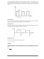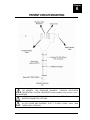
1
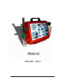
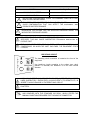
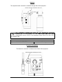
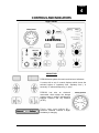
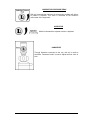
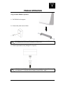
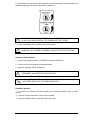
LUNG VENTILATOR PR4D-02 R 04-04 (24) REV 06 CERTIFICATE GMP NBR ISO 9001:2008 EN ISO 13485:2003 + AC 2009 CONTENTS GUIDELINES AND DECLARATIONS................................................................... 4 PRESENTATION................................................................................................... 8 GENERAL......................................................................................................................... PHYSICAL CHARACTERISTICS....................................................................................... EXTERNAL POWER SOURCE.......................................................................................... INTERNAL POWER SOURCE........................................................................................... ENVIRONMENTAL SPECIFICATIONS.............................................................................. PNEUMÁTICS INPUTS...................................................................................................... 8 8 9 9 9 10 WARNINGS, PRECAUTIONS AND NOTES..................................................................... 10 INTRODUCTION.................................................................................................... 12 INDICATORS...……………................................................................................................ ELECTRÔNIC CONTROLS............................................................................................... CONTROLES PNEUMÁTICOS......................................................................................... 12 12 12 FIXING AND CONNECTIONS............................................................................... 13 FIXING…………………………........................................................................................... CONNECTING TO THE ELECTRIC SOURCE.................................................................. CONNECTING TO GAS SOURCE.................................................................................... INPUT PRESSURE............................................................................................................ RESPIRATÓRY CIRCUIT.................................................................................................. ASPIRATOR...................................................................................................................... FLOWMETER (HUMIDIFIER)............................................................................................ 13 13 13 14 14 15 15 INDICATORS AND CONTROLS........................................................................... 17 FRONT PANEL................................................................................................................. 17 INDICATORS...……………................................................................................................ 17 CONTROLS....................................................................................................................... INSPIRATÓRY TIME......................................................................................................... FREQÜÊNCY.................................................................................................................... LEFT SELECTION KEYS................................................................................................... EXPIRATÓRY TIME........................................................................................................... I:E RATIO......……………................................................................................................... RIGHT SELECTION KEYS................................................................................................ PATIENT FLOW................................................................................................................. INSPIRATORY PEAK PRESSURE................................................................................... ASPIRATOR……............................................................................................................... HUMIDIFIER....................................................................................................................... 18 18 18 18 18 18 18 19 19 19 19 - 1 of 43 - FUNCTIONAL CHARACTERISTICS................................................................................. ENERGY SOURCES…...................................................................................................... CYCLER............................................................................................................................ PARÂMETERS SELECTION..…………...…………………………………………………..... 20 20 20 20 ALARMS SYSTEM............................................................................................................ ALARMS PROGRAMMING................................................................................................ AIRWAY PRESSURE ALARM........................................................................................... PUSHER GAS MISSING ALARM...................................................................................... LOW BATTERY ALARM.................................................................................................... PEEP ALARM.................................................................................................................... ALARMS DEFAULT CONFIGURATION............................................................................ ALARMS VALUES VERIFICATION LIST........................................................................... ALARMS SYSTEM INTEGRITY TEST………………………………..… 24 24 24 25 25 25 25 26 26 PATIENT CIRCUIT ASSEMBLY..............…….................................................................. 28 PR4D-02 OPERATION...................................................................................................... 30 CLEANING, DESINFECTION AND STERILIZATION....................................................... 33 DIAGRAMS..................................................................................................................... 34 SIMBOLOGY.................................................................................................................... 36 ACCESSÓRIES…………………………………..................................................................... 39 PREVENTIVE MAINTENANCE........................................................................................... 41 RADFORD TABLE...........……………………………………………….…………………...….. 42 TABLE FOR FREQUENCY DETERMINATION ACCORDING TO THE WEIGHT OF YOUNG AND ADULT PATIENTS........................................................................................ 42 TABLE FOR FREQUENCY DETERMINATION ACCORDING TO THE WEIGHT OF PEDIATRIC AND NEONATAL PATIENTS........................................................................... 43 WARRANTY......................................................................................................................... 44 - 2 of 43 - GUIDELINES AND DECLARATIONS OF LEISTUNG EQUIPAMENTO LTDA. ABOUT ELECTROMAGNETIC COMPATIBILITY (EMC) Manufacturer guidelines and declarations – Electromagnetic emission The PR4D-02 is designated for use in electromagnetic ambience as specified bellow. It is recommended that the PR4D-02 user ensures it to be utilized in such ambience. Emission tests RF Emission ABNT NBR IEC CISPR11 RF Emission ABNT NBR IEC CISPR11 Compliance Group 1 Class A Harmonic Emissions IEC 61000-3-2 Not Applicable Emissions due to the fluctuation of voltage flicker IEC 61000-3-3 Not Applicable RF Emission CISPR 14-1 RF Emission CISPR 15 Complies Complies Electromagnetic ambience - guidelines The Lung Ventilator PR4D-02 uses RF energy only for its internal functions. However, its RF emissions are very low and are unlikely to cause any interference in nearby electronic equipments. The Lung Ventilator PR4D-02 is suitable for use in all non-residential establishments and for those directly connected to public network distribution of low voltage electricity that supplies buildings for domestic use. The Lung Ventilator PR4D-02 is not suitable for interconnection with other equipment. The Lung Ventilator PR4D-02 is not suitable for interconnection with other equipment. - 4 of 43 - Manufacturer Guidance and Declarations – Electromagnetic immunity The PR4D-02 is designated for use in electromagnetic ambience as specified bellow. It is recommended that the PR4D-02 user ensures it to be utilized in such ambience. Test Level Conformity Electromagnetic Environment Emission Tests Level – Guidance ABNT NBR IEC 60601 Electrostatic Discharges (ESD) ± 6 kV by contact IEC 61000-4-2 ± 8 kV by air Fast Transient Burst (FTB) ± 2 kV at Inlet line Not applicable ± 1kv at I/O lines IEC 61000-4-4 Surges ± 1 kV line(s) to line(s) IEC 61000-4-5 ± 2 kV line(s) to earth Voltage drops, short interruptions and voltage variations on the lines of power input < 5% U t IEC 61000-4-11 40% Ut Floors should be wooden-made, concrete or ceramic. If the floors are covered with synthetic material, relative humidity should be at least 30%. Not applicable Quality of power supply should be the same of a typical commercial or hospital environment. Not applicable Quality of power supply should be the same of a typical commercial or hospital environment. Not applicable Quality of power supply should be the same of a typical commercial or hospital environment. (> 95% voltage drop of Ut) by 0.5 cycles. (60% voltage drop of Ut) by 5 cycles 70% Ut (30% voltage drop of Ut) by 25 cycles. < 5% Ut (> 95% voltage drops of Ut) by 5 seconds. Magnetic fields at power line frequency 3 A/m Not applicable - 5 of 43 - Magnetic fields at power supply frequency should be the same of a typical commercial or hospital environment. Manufacturer Guidance and Declarations – Electromagnetic Immunity The Lung Ventilator PR4D-02 is intended for use in electromagnetic environment specified below. It is recommended that the client or user of Lung Ventilator PR4D-02 ensure that it is used in such environment. Test Level Emission Conformity Electromagnetic Environment – Guidance ABNT NBR IEC Tests Level 60601 RF portable and mobile communication equipments should not be used near any part of the Lung Ventilator PR4D-02, including cables, with separation distance less than the recommended, calculated from the equation applicable to the transmitter frequency. Separation distance recommended: ½ RF Conducted 3 Vrms d= 1,16 [ P ] IEC 61000-4-6 150 kHz to 80 MHz A out of bandwidth ISM d= 1,2 [ P ] ½ 10 Vrms d= 1,2 [ P ] ½ 80 MHz to 800 MHz d= 2,3 [ P ] ½ 800 MHz to 2,5 GHz 150 kHz to 80 MHz A out of bandwidth ISM RF Radiated IEC 61000-4-3 10 V/m Not applicable Where P is the maximum nominal power output of transmitter, in watts (W), according to transmitter manufacturer, and d is B the recommended separation distance, in meters (m). 80 MHz to 2,5 GHz The field intensity established by RF transmitter, as c determined by electromagnetic inspection at the local should D be less than compliance level in each frequency band . Interference may occur around the equipment marked with this symbol. NOTE 1. At 80 MHz and 800 MHz applies the highest range of frequency. NOTE 2. This guidance may be not applicable in all situations. The electrom agnetic propagation is affected by absorption and reflection of structures, objects and people. A The bandwidth ISM (Industry, medical and scientific), between 150 kHz and 80 MHz are 6.765 MHz; 13.553 MHz to 13.564 MHz; 26.957 MHz to 27.283 MHz and 40.66MHz to 40.70MHz. B The compliance level in the bandwidth ISM between 150KHz and 80MHz and in the frequency range between 80MHz to 2,5GHz, intends to reduce the probability of mobile and portable communication equipments to cause interference if they are inadvertently brought to the patient´s environment. For this reason, an additional factor of 10/3 is used to calculate the recommended separation distance for transmitter in range of frequency. C The field intensity established by fix transmitters, like base transceiver stations, telephone (cellular and wireless), land mobile radio, amateur radio, AM and FM transmitter and TV transmitter, can´t be predicted theoretically with accuracy. To evaluate the electromagnetic environmental due to RF fix transmitters, it is recommended to consider a local electromagnetic inspection. If the local field intensity where the Lung Ventilator PR4D-02 is located exceeds the above applicable RF compliance level, the Lung Ventilator PR4D-02 should be observed in order to verify the normal operation. If an unusual performance is observed, additional procedure m ay be necessary, such as reorienting or replacement of Lung ventilator PR4D-02. D Above the frequency range of 150kHz, the field intensity should be smaller than (v1) V/m. - 6 of 43 - Recommended separation distances between portable and mobile RF communication equipments and the Lung Ventilator PR4D-02 The Lung Ventilator PR4D-02 is intended for use in an electromagnetic environment in which radiated RF disturbances are controlled. The customer or the user of the Lung Ventilator PR4D-02 can help prevent electromagnetic interference by maintaining a minimum distance between portable and mobile RF communications equipment (transmitters) and the Lung Ventilator PR4D-02 recommended below, according to the maximum output power of the communications equipment. Rated maximum output power of transmitter W Separation distance according to frequency of transmitter m 150 kHz to 80 MHz out of Bandwidth ISM d= 1,16 [ P ] ½ 150 kHz to 80 MHz out of Bandwidth ISM d= 1,2 [ P ] ½ 800 MHz to 2,5GHz 80 MHz to 800 MHz d= 1,2 [ P ] ½ d= 2,3 [ P ] 0,01 0,11 0,12 0,12 0,23 0,1 0,36 0,37 0,37 0,72 1 1,16 1,2 1,2 2,3 10 3,68 3,79 3,79 7,27 100 11,67 12 12 23 ½ For transmitters rated at a maximum output power not listed above, the recommended separation distance d in metres (m) can be estimated using the equation applicable to the frequency of the transmitter, where P is the maximum output power rating of the transmitter in watts (W) according to the transmitter manufacturer. NOTE 1 At 80 MHz and 800 MHz, the separation distance for the higher frequency range applies NOTE 2 At bandwidth ISM (Industrial, Scientific and Medical), between 150 kHz and 80 Mhz, there are 6,765 MHz to 6,795 MHz; 13,553 MHz to 13,567 MHz; 26,957MHz to 27,283 MHz e 40,66 MHz to 40,70 MHz. NOTE 3 An additional margin of 10/3 is used to calculate the separation distance recommended for transmitters in the bandwidth ISM between 150kHz and 80Mhz and the bandwidth 80 MHz to 2,5 GHz to reduce the interference probability from communication mobile equipment could cause if it be carried unwarned in patient area. NOTE 4 These guidelines may not apply in all situations. Electromagnetic propagation is affected by absorption and reflection from structures, objects and people. - 7 of 43 - Chapter 1 PRESENTATION In this User Manual, are presented the necessary information for the correct use of the Lung Ventilator PR4D-02. The indications relating to enforcement and regulations, mentioned in this manual, is a guideline, the physician should adapt, as their criterion, the needs of patients. LEISTUNG EQUIPAMENTOS LTDA. 202 João Ropelatto St. City: Jaraguá do Sul – Santa Catarina District: Nereu Ramos POSTAL CODE: 89265-300 Phone: 55 (47) 3371-2741 Fax: 55 (47) 3371-9267 CNPJ 04.187.384/0001-54 Estate registration 254.417.108 Technical Supervisor: Engº Fernando Alves Negrão CREA/SC 0771605 Legal Supervisor: Marcelo Javier Fernandez ______________________________ Operation authorization ANVISA No. GHL3983MX9H2 Certificate GMP: Registry ANVISA No. 80203470007 Website: www.leistungbrasil.com/eng E-mail: [email protected] GENERAL MODEL PR4D-02 Registry ANVISA No. 80203470007 MEDICAL DEVICE CLASSIFICATION OPERATION MODE CLASS III Continuous operation CLASS II Internally Energized Device Classification according to type against electrical shock (insulation). Classification according to type of protection against electrical shock (applied part). TYPE B Level of protection against water penetration IPX0 Equipment not suitable for use in the presence of flammable anesthetic mixture with air, oxygen or nitrous oxide PHYSICAL CHARACTERISTICS Dimensions (Ventilator) PARAMETERS VALUES High 150 mm 270 mm 230 mm Width Depth - 8 of 43 - EXTERNAL POWER SOURCE NOMINAL VOLTAGE 10.5 V to 14V NOMINAL CURRENT 1.20A ~ 0.85A NOMINAL POWER 12.5 W INPUT FUSE 2.5A/250V - 20mm SB REPLACE THE FUSE ONLY WITH OTHER WITH THE SAME CURRENT AND VOLTAGE SPECIFICATIONS INTERNAL POWER SOURCE 12 V Nominal voltage Nominal capacity Type Autonomy Capacity affected by temperature Auto-discharge 68ºF (20ºC) Maximum Discharge Current 77ºF (25ºC) Charge (Floating Voltage) Charging Time (Battery Discharged) 2.2Ah VRLA (Sealed, does not emit gas) Complete battery charge 120 minutes autonomy 77ºF (25ºC) 104ºF (40ºC) 102% 77ºF (25ºC) 100% 32ºF (0ºC) 85% 5ºF (-15ºC) 65% Capacity after 3 months 90% Capacity after 6 months 80% Capacity after 12 months 60% 48A (5s) Floating 77ºF (25ºC) 13.6 – 13.8V / 1.25A (max). Vmin=10.5V 4 Hours Maximum temperature 131ºF (55ºC) Internal fuses 2.5A 20mm SB SPECIFICATIONS INFORMED BY BATTERY MANUFACTURER. THE INTERNAL BATTERY AND FUSE ARE NOT REPLACEABLE BY OPERATOR THE SWITCHING FOR INTERNALLY BATTERY OCCURS AUTOMATICALLY WITHOUT THE NECESSITY OF EXTERNAL INTERVENTION. IT DOES NOT MODIFIES THE EQUIPMENT OPERATION OR INSPIRATORY PRESSURE AT THE OUTPUT FOR THE PATIENT. ENVIRONMENTAL SPECIFICATIONS Environment Temperature Relative Humidity Atmospheric Pressure Operation Storage – Transport Operation Storage – Transport Operation Storage – Transport PNEUMATIC INPUTS OXYGEN VALUES 10ºC to 35ºC 2ºC to 40ºC (*) 10% to 95% Not condensable 0% to 95% Not condensable 66 – 100 kPa 66 – 100 kPa Input DISS 9/16” – 18 - 9 of 43 - From 2.8 to 7 kg/cm2 Up to 100 l/min PRESSURE FLOW USE ONLY MEDICAL GRADE GAS. THE MEASURE OF VOLUME AND PRESSURE IS STANDARDIZED BY BAROMETRIC PRESSURE AT SEA LEVEL, BODY TEMPERATURE AND WATER VAPOR SATURATE (BTPS) AND THEY ARE ADJUSTED IN FUNCTION OF ALTITUDE. (*) THE STORAGE OF THE LUNG VENTILATOR FOR LONG PERIODS AT TEMPERATURE GREATER THAN 27ºC, OR WITHOUT ELECTRICAL CONNECTION FOR PERIODS GREATER THAN 2 MONTHS, MAY AFFECT THE INTERNALLY BATTERY UTILE LIFE. WARNINGS, CAUTIONS AND NOTES WARNINGS Constant attention of specialized personnel is required when patient is connected. Operation problems require immediate corrective action. The professional in charge of its use should, using your own criterion and knowledge, adjust the equipment according to the patient needs. Do not use this equipment in the presence of flammable anesthetic mixture with air, oxygen or nitrous oxide. Do not use anti-static tubes or electrical conductor in the patient circuitry. Do not sterilize the equipment with ethylene oxide. There is a high probability to occur irreversible damage in the ventilator components. The equipment may be affected by High Frequency Electromagnetic Interference (such as cellular, wireless telephone, defibrillators, electro-surgical knifes, magnetic resonance, etc.). Keep these emission sources at least 3(three) meters away from the equipment. Before first utilization and after utilization in each patient, it is necessary to clean the ventilator. To sterilize the accessories, follow the instructions on chapter 8. PRECAUTIONS During the warranty period, the stay or movement of equipment should be performed with the original packaging, with its internal correspondent protection, otherwise will result in loss of warranty. Never sterilize the ventilator, the internal components is not compatible with sterilization techniques. Follow the instructions at chapter 8 for equipment cleaning and accessories sterilization. Never operate the equipment exposing it to direct heat or sunlight. - 10 of 43 - Never cover or place the equipment in order to block the air entry for cooling. To ensure electrical protections and avoid risk of fire, never change the fuses. If the equipment does not work, contact the Authorized Technical Support. The improper replacement of the fuses nullifies warranty and represents a risk for the equipment operation, operator and patient safety. NOTES The ventilator is a medical device that has to be operated by qualified and trained personnel, supervised by a doctor. When PR4D-02 is in use, alternative ventilation way must always be available. The PR4D-02 is produced with recyclable materials and should not be thrown into common landfills because it contains toxic materials to nature, for this, contact an authorized dealer. Electric Diagrams, Circuitry Diagrams, component list, repair instructions and training can be provided by Leistung Equipamentos Ltda, by agreement between both parts. Leistung Equipamentos Ltda. is a company of continuous improvement in its products and technical specifications can change without notice. - 11 of 43 - Chapter 2 INTRODUCTION The Lung Ventilator PR4D-02 is micro-controlled and developed within the cut edge technology, and offers a reliable working tool for patient transports that need mechanical ventilations. The PR4D-02 is easy to operate, because it has an extremely functional designed panel, which permits the operator to use all parameters using few control keys, doing the professional work pleasurable and permits the operator to focus on the patient relationship. It has an agile and safe patient circuitry interconnection system, preventing any error possibility. INDICATORS AIRWAY PRESSURE MANOMETER - LUMINOUS INSPIRATÓRY TIME – SELECTABLE - LUMINOUS EXPIRATÓRY TIME – SELECTABLE - LUMINOUS TOTAL FREQUENCY – SELECTABLE - LUMINOUS I:E RATIO - SELECTABLE - LUMINOUS OS THE SELECTABLE INDICATORS ARE VISUALIZED IN TWO SERIES OF LUMINOUS DISPLAYS. ELECTRÔNIC CONTROLS FREQUENCY 5 to 60 cpm I:E RATIO 1:1.0 to 1:5.0 INSPIRATORY TIME EXPIRATORY TIME OS THE TIME VALUES DEPEND ON THE SELECTED FREQUENCY AND I:E RATIO. PNEUMATIC CONTROLS PATIENT FLOW INSPIRATORY PEAK PRESSURE ASPIRATOR ADJUSTMENT FLOWMETER ADJUSTMENT - 12 of 43 - Chapter 3 FIXING AND CONNECTIONS FIXING To fix the equipment support with two screws in the desired place, making sure that it is really firm. Use the two screws that come laterally in the equipment to fix the equipment at the support. CONNECTING TO EXTERNAL POWER SOURCE The electrical connection is in the bottom of the equipment and it has a P10 Plug with the polarity indicated as shown in the figure. VERIFY IF THE CONNECTION OF THE EQUIPMENT PERFORMED TO ENSURE A SMOOTH OPERATION. IS PROPERLY VERIFY IF THE JACK (P10 FEMALE) IS COINCIDENT WITH THE PLUG (P10 MALE) BEFORE CONNECT THE EQUIPMENT. CONNECTING TO GAS SUPPLY The pneumatic connection is in the bottom of the equipment. OXYGEN INLET Male connector DISS 9/16”-18 OXYGEN CONSUMPTION 3 to 6 l/min. AT THE EDGE OF THE PRESSURE TUBE ARE USED CORRESPONDENT FEMALE CONNECTORS. IT IS POSSIBLE TO USE AS INPUT GAS AIR OR OXYGEN, BUT THE EQUIPMENT DOES NOT MIX THEM. THE THREAD CONNECTORS USED IN THE GAS INLET COMPLIES WITH NBR 11906 AND ISO 5359 STANDARD THAT GIVE THE MINIMUM CONDITIONS FOR THIS KIND OF CONNECTORS. THE EQUIPMENT GAS INPUT IS MADE WITH A RETENTION UNIDIRECTIONAL VALVE, WHICH AVOIDS THE REVERSE FLOW THROUGH INLET PORT REVERSO DE GÁS ATRAVÉS DA PORTA DE ENTRADA - 13 of 43 - INPUT PRESSURE OXYGEN 2.8 to 7 kg/cm2 MINIMUM FLOW NEEDED 60 l/min. MAXIMUM FLOW 100 l/min DO NOT USE THE EQUIPMENT CLOSE TO FLAMMABLE ANESTHETIC GAS, RISK OF FIRE OR EXPLOSION. IT MUST BE USED COMPRESSED CLEAN AND DRY OXYGEN, IN ORDER TO AVOID CONTAMINATION THAT CAN AFFECT THE EQUIPMENT AND PRODUCE BAD PERFORMANCE. THE LUNG VENTILATOR PR4D-02 HAS AN INTERNAL PRESSURE REGULATOR THAT AVOIDS, FOR THE SPECIFIED PRESSURE RANGE, THE INSPIRATORY PRESSURE LOSSES. DO NOT LET THE INLET GAS PRESSURE BE LESS THAN THE LOW SPECIFIED, THIS MAY CAUSE INSPIRATORY PRESSURE REDUCTION AT PATIENT PORT. THE LUNG VENTILATOR PR4D-02 DOES NOT HAVE INTERNAL AIR COMPRESSOR, SO WHEN THE INLET GAS ENDS, THE EQUIPMENT STOPS CYCLING. BREATHING CIRCUIT The breathing circuit connection is located at the front of the equipment. Use breathing circuits according to the patient type: adult, pediatric or neonatal, the difference is on the tube internal diameter. WHEN USING BREATHING CIRCUITS THAT USES WATER TRAPS IN THEIR LINES (INSPIRATORY / EXPIRATORY), ALWAYS VERIFY ITS HERMETICITY, IN ORDER TO AVOID LEAKAGE IN THE BREATHING CIRCUIT. VERIFY THE PROPER POSITION OF EXPIRATORY VALVE DIAPHRAGM, SEE CHAPTER 6. THE PATIENT BREATHING CIRCUIT CONNECTOR IS 22MM CONICAL TYPE AND COMPLIES WITH THE STANDARD ISO 5356-1, WHICH STATES THE MINIMAL CONDITIONS REQUIRED FOR THIS KIND OF CONNECTOR. - 14 of 43 - Aspirator The aspiration bottle connection is located at the right side of the equipment. THE THREADED CONNECTION USED IN THE ASPIRATOR (VACCUM CONNECTOR) IS ACCORDING TO THE NBR 11906 AND ISO 5359 STANDARDS, WHICH STATES THE MINIMUM CONDITIONS FOR THIS TYPE OF CONNECTION. ASPIRATOR SUCTION MAXIMUM ASPIRATION 20 cmHg Flowmeter (Humidifier) The flowmeter connection is located at the left side of the equipment. - 15 of 43 - A THE THREADED CONNECTION USED IN THE O2 IS ACCORDING TO THE NBR 11906 AND ISO 5359 STANDARDS, WHICH STATES THE MINIMUM CONDITIONS FOR THIS TYPE OF CONNECTION. THE HUMIDIFIER IS BUILT ACCORDING TO ISO 8185 STANDARD, WHICH STATES THE MINIMUM CONDITIONS FOR THIS TYPE OF EQUIPMENT. Outlet Flow OUTLET MAXIMUM FLOW 15 L/min - 16 of 43 - Chapter 4 CONTROLS AND INDICATORS FRONT PANEL INDICATORS PR4D-02 has a system of numeric and luminous indicators. It counts with a set of numeric displays which shows the selected values of inspiratory time, expiratory time ( in seconds), I:E ratio and frequency ( in cpm) PR4D-02 has also an electronic manometer which shows the airways pressure value in cmH2O, expressed for Ambient Pressure and Dry Pressure (ATDP) Electric energy source indicator DC – whenever “External” indicator is alight, the battery is charging. - 17 of 43 - CONTROLS INSPIRATORY TIME With this control the inspiratory time is selected. Pressing this key, a sound is enabled, a luminous indicator is turned on and its numeric value is shown on the left displays set. The inspiratory time is expressed in seconds (s). FREQÜÊNCY With this control the operation frequency is selected. Pressing this key, a sound is enabled, a luminous indicator is turned on and its numeric value is shown on the left displays set. Frequency is expressed in breathes (or cycles) per minute (bpm). LEFT SELECTION KEYS With these keys the value of the selected function is modified. Functions which may vary with these keys are inspiratory time and frequency. A sound is enable by pressing any of these keys. EXPIRATORY TIME With this control the expiratory time is selected. Pressing this key, a sound is enabled, a luminous indicator is turned on and its numeric value is shown on the right display set. The iexpiratory time is expressed in seconds (s). I:E RATIO With this control the relation between the inspiratory and expiratory times is selected. Pressing this key, a sound is enabled, a luminous indicator is turned on and its numeric value is shown on the right displays set. RIGHT SELECTION KEYS With these keys the value of the selected function is modified. Functions which may vary with these keys are expiratory time and I:E ratio. A sound is enabled by pressing any of these keys. PATIENT FLOW With this command the flow of oxygen which will be delivered to the patient by the ventilator is adjusted. - 18 of 43 - INSPIRATORY PRESSURE PEAK With this command the maximum of pressure the ventilator will deliver to patient is adjusted. This value is visualized at the electronic manometer of the equipment. ASPIRATOR With this command the aspirator suction is adjusted. HUMIDIFIER Through flowmeter connected to the cup, this set is used as humidifier. Flowmeter button is used to adjust the flow value in l/min. - 19 of 43 - Chapter 5 FUNCTIONAL CHARACTERISTICS ENERGY SOURCES For its operation this equipment requires electric energy of 12V direct current type (10.5Vdc to 14Vdc). The equipment has in its bottom part outlets for correspondent electric external source and internal support for 12V/2.2Ah battery. When the inlet voltage is lower than 13Vdc the net sensor may indicates the equipment is operating by battery, to avoid operation with bad low voltage sources. Avoid working with external power source lower than 12 Vdc because the battery may be discharged. When the external power source or battery reaches values lower than 11Vdc, displays may get turned off and “low battery” alarm will be activated. Because it is a transportable equipment, when disconnection of inlet power source occurs, the indicator LED light changes from “external source” to “battery” without activating any sound alarm. CYCLING This equipment counts with a micro processor, which commands its operation within a huge frequency range. It makes possible to handle inspiratory curve, adapting it to each clinic case. PARAMETERS SELECTION I/E - Inspiratory time – Expiratory time - Frequency Parameters FREQUENCY 5 to 60 c.p.m I:E RATIO 1:1.0 to 1:5.0 INSPIRATORY TIME 0.1 to 6.0 seconds EXPIRATORY TIME 0.5 to 9.9 seconds Initial Parameters FREQUENCY 15 c.p.m I:E RATIO 1:2.0 INSPIRATORY TIME 1.3 seconds EXPIRATORY TIME 2.6 seconds - 20 of 43 - The following graphic illustrates, through electrovalve behavior, the operation of the parameters digitally adjustable. When the electrovalve is turned on, indicated by the high voltage level, there is the inspiratory time and when it is turned off there is the expiratory time. Inspiratory time Is the time the ventilator provides a gas flow to the patient, generating a positive inspiratory pressure. Changing this parameter changes I:E ratio and frequency. Expiratory time Is the time the ventilator stops providing gas to the patient and allows the patient to expire. Changing this parameter changes I:E ratio and frequency. Respiratory cycle It is the sum of inspiratory time and expiratory time T cycle = T ins + Tex Frequency Indicates the quantity of cycles occurred during one minute. Changing frequency value changes inspiratory time value and expiratory time value, but always maintains the same I:E ratio. F= 60 T ciclo - 21 of 43 - I:E Ratio It is a proportion between inspiratory time and expiratory time. Changing I:E ratio changes inspiratory time and expiratory time. I:E = Tins Tex Exemple: For initial parameters: T cycle = T ins + Tex T cycle = 1.3 + 2.6 = 3.9 s F= 60 3,9 F = 15 c.p.m. I:E = Tins 1,3 Tex = 2,6 = 1 2 If inspiratory and expiratory times are changed to 3.0 s: T cycle = T ins + Tex T cycle = 3.0 + 3.0 = 6.0 s 60 10 c.p.m. 6,0 = Tins 3,0 1 I:E = Tex = 3,0 = 1 F= PR4D-02 has frequency and I:E ratio as main parameters because inspiratory and expiratory time values depend exclusively on them. Adjusting parameters: 1 – Choose the frequency. You can use the annex 4 as orientation. ANNEX 4 TABLES MAY BE USED AS ORIENTATION TO DETERMINE THE FREQUENCY, ACCORDING TO PATIENT WEIGHT, BUT THE OPERATOR MUST ADJUST THE PARAMETERS ACCORDING TO HIS OWN CRITERIA, IN ORDER TO SUPPORT THE PATIENT. 2 – Adjust I:E ratio, inspiratory and expiratory time values are automatically adjusted. THE STEPS ILUSTRATED HERE ARE ONLY ORIENTATIVE, THE PARAMETERS ADJUSTMENT MUST BE DONE BY THE OPERATOR ACCORDING TO HIS OWN CRITERIA. CHANGING I:E RATIO, INSPIRATORY AND EXPIRATORY TIMES AND THE FREQUENCY, MAY CHANGE OTHER PARAMETERS BECAUSE THEY ARE ALL CONNECTED. - 22 of 43 - FLOW AND INSPIRATORY PRESSURE ADJUSTMENT. For a determined inspiratory maximum adjusted peak pressure valuePara um determinado valor de Pico de Pressão Inspiratório máximo ajustado, patient flow value is what determines the flow ascendant ramp inclination. As PR4D-02 is time controlled and pressure limited, the adjusted maximum pressure will never be overpassed. If inspiratory time value is not enough and flow adjusted value is low, may occur that the equipment will not reach maximum pressure value. O2 CONCENTRATION VARIATION O2 concentration variation is done through inspiratory flow adjusted value and may vary from 35% (maximum inspiratory flow) to 50% (minimum inspiratory flow) and for values within this range the O2 concentration assume values between 30% and 50% approximately. - 23 of 43 - Chapter 6 ALARMS SYSTEM ALARMS PROGRAMMING They are located at the right side of the panel a variety of alarms, each one with specific roles which grants safety during ventilation, minimizing the risks and detection time of ventilation anomalies which implies on risks for the patient. Always an alarm is triggered, besides the sound signal, a LED light signal starts flashing, indicating the cause of the alarm. Upon solving the cause of the alarm, automatically or by the operator, the sound signal stops and the LED indicator flashing stops, maintaining it turned on continually. - ALL ALARMS ARE HIGH PRIORITY ONES AND REQUIRE CORRECTIVE IMMEDIATE ACTION BY THE OPERATOR. AIRWAYS PRESSURE ALARMS To monitor the respiratory system pressure during inspiration. Maximum Pressure: interrupts the inspiration if inspiratory pressure reaches a determined pressure level, protecting the lung against pressure intensity that may cause a barotrauma. It is activated at any time during inspiration and remains up to one cycle after problem solution. The level for alarm activation is adjusted through the “High Ins. Pressure”, located below the indicative LED’s and varies from 10 to 100 cmH2O. Minimum Pressure: warns if during inspiration the adjusted minimum pressure value is not reached, which may be caused by an accidental disconnection from the equipment or patient circuit leakage. It is activated by inspiratory pressure at the end of inspiration measurement. It is necessary three inspiratory cycles to get activated and one cycle to get deactivated after problem solution. The value for trigger the alarm is adjusted by the “Low Insp. Pressure”, located below the indicative LED’s and varies from 2 to 30 cmH2O. - 24 of 43 - THE MAXIMUM PRESSURE ALARM VALUE LIMITS THE ADJUSTMENT VALUE OF INSPIRATORY PRESSURE. INLET GAS MISSING ALARM Measures the pressure of inlet gas at the equipment gas input, whenever the gas pressure is lower than 3.5 Kgf/cm2 the alarm is triggered, returning to the normal condition after resolved the problem. LOW BATTERY ALARM Measures the battery voltage level of the equipment, which for values lower than 11V (equivalent to 90% of battery autonomy) the alarm is triggered, returning to the normal condition after resolved the problem. PEEP ALARM Measures the pressure level at the end of expiration; it is triggered when this pressure varies in + or – 3 cmH2O of the predetermined value. It is necessary two expiratory cycles to trigger this alarm, returning to the normal condition after resolved the problem. The adjustment of this alarm is made by the following way: - The PEEP value is adjusted (for this, is necessary to use a PEEP valve at the exahlatory valve, purchased separately). - When PEEP alarm starts, “RESET” key is pressed, the PEEP value will be adjusted to the real pressure value of airways at the moment the key was pressed. - The PEEP value will be adjusted only if PEEP alarm was activated. - THIS ALARM MAY BE USED FOR DETECTION OF CONTINUOUS PRESSURE LIMIT, WHENEVER THE EQUIPMENT STARTS; THE PEEP VALUE IS TAKEN AS BEING 0 CMH2O AND ANY CONTINUOUS PRESSURE ABOVE 3 CMH2O AT AIRWAYS WILL TRIGGER THE PEEP ALARM. - DUE TO OPERATING LOGIC OF THE PEEP ALARM DEPENDS ON “RESET” KEY, ALWAYS BE CAREFULL UPON ACTIVATING THIS KEY, TO AVOID UNDUE ADJUSTMENTS OF PEEP ALARM. Parameter Max. Ins. Pressure Min. Ins. Pressure Inlet gas missing Low battery PEEP ALARMS DEFAULT CONFIGURATION Initial Value Adjustable? Depends on adjust. Yes Depends on adjust. Yes 3,5kgf/cmH2O No 11V (Battery) No 00 cmH2O Yes Adjustment range 10 - 100 cmH2O 2 - 30 cmH2O 0 – 100 cmH2O - ALARMS PARAMETERS ADJUSTMENT MUST BE DONE BY OPERATOR, CONSIDERING EACH CLINIC CASE, BEFORE INITIATING THE VENTILATION. - 25 of 43 - - IT IS RECOMMENDED TO BE CHECKED BY THE OPERATOR OR USER, THE ALARMS VALUE VERIFICATION LIST, SPECIALY IN EVENTUAL CHANGES OF OPERATORS. - AFTER TOTAL ENERGY/BATTERY LOSS AND FURTHER RETURN, THE EQUIPMENT RESTARTS WITH THE ALARMS DEFAULT CONFIGURATION. PATIENT ALARMS VALUE VERIFICATION LIST OPERATION MODE ADULT PCV PEDIATRIC PCV CHECK P max P min P max P min ALARMS SYSTEM INTEGRITY TEST 1 – Turn on the equipment, with the test balloon connected to. Through “High Ins. Pressure” button, adjust for a value lower than peak value, shown at the electronic manometer. It must trigger “Maximum Pressure” alarm and after each cycle, outlet flow must be cut. 2 – Adjust the value of Pmin for a value bigger than peak value, shown at the display and disconnect the test balloon. After three cycles of inspiration, it must trigger “Minimum Pressure” alarm. 3 – Maintain PEEP alarm in zero and adjust the PEEP valve for any value. It must triggers PEEP alarm. 4 – Disconnect the O2 hose from gas inlet. It must triggers “Inlet Gas” alarm. 5 – Disconnect the power cable from the external power source. It must turn on “Battery” LED. 6 – Make the inlet power source voltage be lower than 100.0 Vdc. It must trigger “low battery” alarm. - EACH TEST IS INDEPENDENT OF EACH OTHER, SO THEY CAN BE TEST IN OTHER ORDER THAT WAS SUGGESTED. - THE TIME BETWEEN PARAMETER ADJUSTMENT AND ALARM ACTIVATION MAY VARY ON EACH TEST. - IT IS RECOMMENDED THIS TEST TO BE DONE ALONG WITH PREVENTIVE MAINTENANCE. - 26 of 43 - Chapter 6 PATIENT CIRCUIT MOUNTING WHEN RESPIRATORY CIRCUIT COMPONENTS OR OTHER COMPONENTS OR SUBSETS, THE PRESSURE GRADIENT, THROUGH VENTILATOR RESPIRATORY SYSTEM, MEASURED FROM CONNECTION PATIENT PORT, MAY INCREASE. A BAD CLOSING OF THE DIAPHRAGM MAY WILL RESULT IN A WRONG EXPIRED PARAMETERS LECTURE. THE DIAPHRAGM MUST LEAN THE COVER ACOMMODATION. FIRST PUT IT IN THE COVER AND ENSURES THAT IT IS WELL LEANT, ONLY THEN THREAD WITH THE BODY. - 27 of 43 - DO NOT THREAD STRONGLY THE COVER WITH THE BODY WHEN THE SCREW GETS IN THE END. THREAD IT SOFTLY. THE PATIENT CIRCUIT TYPE B IS BUILT WITH MATERIAL CERTIFIED BY FDA (FOOD AND DRUGS ADMINISTRATION) WHICH GRANTS THE BIOCOMPATIBILITY OF THIS MATERIAL. THE COPY OF THE CERTIFICATE CAN BE GOTTEN WITH THE MANUFACTURER. THE PATIENT CIRCUIT CONNECTOR IS ACCORDING TO NBR 13476 STANDARDS. THE TUBE USED IN THE RESPIRATORY SYSTEM OF THE VENTILATOR IS ACCORDING WITH NBR13274 AND ISO 5367, RELATED TO RESPIRATORY TUBES FOR USE IN RESPIRATORY SYSTEMS AND VENTILATORS. - 28 of 43 - Chapter 7 PR4D-02 OPERATION Lung Ventilator PR4D-02 operation. 1 – Fix PR4D-02 on its support. 2 – Connect the power source 12Vdc. BEFORE CONNECTING, VERIFY IF POWER SOURCING CONDITIONS ARE ACCORDING WITH SPECIFICATIONS OF CHAPTER 1. 3 – Connect pneumatic source (2.8kg/cm2 to 7kg/cm2); BEFORE CONNECTING, VERIFY IF GAS SOURCING CONDITIONS ARE ACCORDING TO THE SPECIFICATIONS OF CHAPTERS 1 AND 3. - 29 of 43 - 4 – Connect the patient circuit to the correspondent connector and the nut of inspiratory pressure (chapter 3), the mounting of the circuit is in chapter 6. 5 – Turn on the “on/off” switch of the equipment. PR4D-02 HAS THE FOLLOWING INITIAL DEFAULT PARAMETERS VALUES: Inspiratory Time: 1.3 s - Expiratory Time: 2.6 s - Frequency: 15 c.p.m - I:E ratio: 1:2 6 – Adjust the parameters of time, frequency and I:E ratio using panel keys (as parameters selection in chapter 5): DUE TO BE INTRINSICALLY RELATED, CHANGING I:E RATIO, INSPIRATORY AD EXPIRATORY TIMES AND FREQUENCY, MAY CHANGE VALUE OF THE OTHERS. TABLES OF ANNEX 4 CAN BE USED AS ORIENTATION TO DETERMINE OF THE FREQUENCY, ACCORDING PATIENT WHEIGHT, BUT THE OPERATOR MUST ADAPT THE PARAMETERS AS HIS OWN CRITERIA, TO THE NEEDS OF THE PATIENT. - 30 of 43 - 7 –Adjust maximum pressure through inspiratory pressure peak button and flow delivered to patient through patient flow button (as shown in chapter 4): THE OPERATOR MUST ADAPT THE PARAMETERS OF PRESSURE AND FLOW AS HIS OWN CRITERIA, TO THE NEEDS OF THE PATIENT. 8 – Connect exhalatory valve of patient circuit to the patient. THE CONNECTION OF THE LUNG VENTILATOR TO THE PATIENT MUST BE DONE ONLY BY TRAINED PERSONNEL, QUALIFIED FOR THIS FUNCTION. Aspiration bottle operation 1 – Connect the aspiration bottle to the PR4D-02 connector (Chapter 3); 2 – Connect a hose to the beak of the aspiration bottle. 3 – Open the “Aspirator” button (Chapter 4); THE ASPIRATION MANEUVER MUST BE DONE ONLY BY TRAINED PERSONNEL, QUALIFIED FOR THIS FUNCTION. USE ONE OF THE METHODS DESCRIBED AT CHAPTER 8 FOR CLEANING AND STERILIZATION OF THE ASPIRATION BOTTLE. Humidifier operation 1 – Connect the flowmeter with the humidifier cup containing distilled water or saline solution; 2 – Connect a proper mask at the output of the humidifier; 3 – Open the flowmeter button to get the desired flow value; - 31 of 43 - Chapter 8 CLEANING, DISINFECTION AND STERILIZATION The parts in touch with the patient can be completely sterilized. The protocols which define the method and frequency must be adapted to the procedures of decontamination and cleaning here indicated as guides. The respiratory circuit and its parts must be replaced sterilized or disinfected elements. Once removed from the equipment, the patient circuit must be dismounted, so that all its parts get previously cleaned (remove traces of blood and other wastes). The methods enabled for disinfection which depend on thermolability are: PVC patient circuit, exhalatory valve, aspiration bottle and humidifier cup: Ethylene oxide – 55% Pasteurization – 75% ETHYLENE OXIDE IS TOXIC, ALL COMPONENTS MUST BE PREVIOUSLY DRIED WHEN PUTTING FOR STERILIZATION, THEY MUST BE VENTILATED TO RELEASE THE RESIDUAL GAS. FOLLOW MANUFACTURER RECOMMENDATIONS. THE EXHALATORY VALVE, THE PATIENT CIRCUIT, THE ASPIRATION BOTTLE AND THE HUMIDIFIER CUP ARE NOT AUTOCLAVABLE. FOR THE PATIENT RECOMMENDATIONS. CIRCUIT, CONSULT MANUFACTURER AVOID USE OF PURE ALCOHOL, CLEANING SOLUTIONS THAT CONTAIN ALCOHOL, SOLVENTS, ACETONE, CHLOROFORM TO CLEAN THE RESPIRATORY TUBES OF PLASTIC PARTS. ETHYLENE OXIDE USE MAY ACCELERATE WRINKLES OR ITS DERIVATIVES AND CHANGE PLASTIC CHARACTERISTICS. THE RESPIRATOR (ITS CASE) MUST BE NEITHER CLEANED WITH ETHYLENE OXIDE NOR IN AUTOCLAVE. PATIENT CIRCUIT MUST BE STERILIZED WITH LOW TEMPERATURE SYSTEMS. - 32 of 43 - Chapter 9 DIAGRAMS The figure below represents the pneumatic diagram of PR4D-02 ventilator - 33 of 43 - The figure below is the marked diagram PR4D-02 CPU board - 34 of 43 - Annex 1 SIMBOLOGY 1 - STANDARD SYMBOLS MEANING PRINTED ON EQUIPMENT, INTERNAL AND EXTERNAL Symbol Standard Description IEC 60601-1:1994 Symbol No.417-5032 Alternated Current IEC 60601-1:1994 Symbol No.417-5031 Continuous Current IEC 60601-1:1994 Symbol No.417-5017 Functional Ground Terminal IEC 60601-1:1994 Symbol No.417-5019 Protection Ground Terminal IEC 60601-1:1994 Symbol No.348 Warning! Consult accompanying documents. IEC 60601-1:1994 Symbol No.417-5007 ON (Connected to a internal / external power source) IEC 60601-1:1994 Symbol No.417-5008 OFF (Disconnected from internal / external power source) IEC 60601-1:1994 Symbol No.878-02-02 B Type Equipment IEC 60601-1:1994 Símbolo No.417-5172 Class II Equipment IEC 60601-1:1994 Symbol No.878-03-01 Electrical Shock Hazard IEC 417 Symbol No.5016 Fuse ISO 15223:2000 Symbol No.3.3 Consult Accompanying Documents - 35 of 43 - 2 – STANDARD SYMBOLS MEANING PRINTED AT EQUIPMENT PACKAGE: Symbol Standard Description ISO 780:1997 (E) No. 1 FRAGILE Handle carefully ISO 780:1997 (E) No. 3 THIS SIDE UP Indicates de position of the upper side of the package ISO 780:1997 (E) No. 4 PROTECT FROM SUNLIGHT The package cannot be exposed to direct sunlight. ISO 780:1997 (E) No. 6 PROTECT FROM RAIN The package cannot be exposed to the rain. ISO 780:1997 (E) No. 14 MAXIMUM STACKING Indicates the maximum number of packages that can be stacked to storage or transport. ISO 780:1997 (E) No. 17 TEMPERATURE LIMIT Indicates the temperature limit for storage and package handling. - 36 of 43 - 3 – SYMBOLS MEANING PRINTED AT EQUIPMENT USER MANUAL: Symbol Standard -------------------- IEC 60601-1:1994 Symbol No.348 Description ADVERTÊNCIA! WARNING! Condition that has the probability to cause damage to the operator or others. ATTENTION Condition that has the probability to cause damage to the equipment, their accessories or others -------------------- NOTE Specific points of interest to be considered for a correct use. AN 980 MANUFACTURER - 37 of 43 - Annex 2 ACCESSORIES DESCRIPTION FUNCTION PATIENT CIRCUIT WITH EXALATORY VALVE (ADULT CIRCUIT) EQUIPMENT-PATIENT INTERFACE OBS.: MUST BE USED ONLY THE MODEL THAT ACCOMPANY THE PR4D-02 VENTILATOR O2 GAS INLET BEAK GAS SUPPLYING FLOWMETER WITH HUMIDIFIER CUP TO MEASURE THE FLOW AND HUMIDIFY O2. ASPIRATION BOTTLE SECRETION BOTTLE SUPPORT SHAPE TO FIX THE EQUIPMENT IN THE MOBILE UNIT USER MANUAL INFORMATION ABOUT OPERATION, REQUIREMENTS AND FUNCTIONS OF EQUIPMENT. - 38 of 43 - DOBLE CONNECTION (OPTIONAL) TO CONNECT TWO O2 SOURCES, ALLOWING DISCONNECTING ONE OF THEM WITHOUT INTERRUPTING VENTILATOR WORKING. EX. CAN BE USED FOR O2 CILINDER SWAPING OR FROM AMBULANCE TO GURNEY. SILICONE TRACHEA (OPTIONAL) CAN BE FURNISHED WITH THE EQUIPMENT INSTEAD OF PVC TRACHEA. Merely illustrative figures - 39 of 43 - Annex 3 PREVENTIVE MAINTENANCE MAINTENANCE MUST BE DONE BY QUALIFIED PERSONNEL AND RESPECTING CORRESPONDING PROTOCOLS. THE MANUFACTURER CANNOT BE LIABLE BY INJURY OR DAMAGE CAUSED BY BAD UTILIZATION. IT IS RECOMMENDED TO CHANGE THE INTERNAL BATTERY EVERY 4 YEARS. ALWAYS CHECK THE INTERNAL BATTERY BEFORE USE, TESTING THE EQUIPMENT WITHOUT EXTERNAL POWER SUPPLY. IT IS RECOMMENDED TO CALIBRATE THE VENTILATORY PARAMETERS ANNUALLY, USING CERTIFICATED STANDARDS. - 40 of 43 - Annex 4 RADFORD TABLE TABLE USED TO FIND THE FREQUENCY ACCORDING TO PATIENT WEIGHT, IN PEDIATRIC AND ADULT kg GENDER 40 M 40 F 45 M 45 F 50 M 50 F 55 M 55 F 60 M 60 F 65 M 65 F 70 M 70 F 75 M 75 F 80 M 80 F 85 M 85 F 90 M 90 F 100 M 100 F 110 M 110 F 8 9 10 X X X X X X X X X X X X X X X X X X X X X X X X X X X X X X X X X X X X X X X X X X X X X X X X X X X X X X X X X X X X X X X X X X 11 X X X X X X X X X X X X X X X X X X X X X X X X X X FREQUENCY 12 13 14 X X X X X X X X X X X X X X X X X X X X X X X X X X X X X X X X X X X X X X X X X X X X X X X X X X X X X X X X X X X X X X X X X X X X X X X X X X X X X X - 41 of 43 - 15 X X X X X X X X X X X X X X X X X X X X X X X X X X 16 X X X X X X X X X X X X X X X X X X X X X X X X X X 17 X X X X X X X X X X X X X X X X X X X X X X X X X X 18 X X X X X X X X X X X X X X X X X X X X X X X X X X 19 X X X X X X 20 X X X X X X 25 X X X X TABLE USED TO FIND THE FREQUENCY ACCORDING TO PATIENT WEIGHT, PEDIATRIC AND NEONATAL kg GENDER 16 8 8.5 9 X 9.5 X 10 X 11 X 12 X 13 X 14 X 15 X 20 M X 20 F X 25 N X 25 F X 30 M X 30 F X 35 M X 35 F X 17 X X X X X X X X X X X X X X X X 18 X X X X X X X X X X X X X X X X X X 19 X X X X X X X X X X X X X X X X X X FREQUENCY 20 22 25 X X X X X X X X X X X X X X X X X X X X X X X X X X X X X X X X X X X X X X X X X X X X X X X X X X X X X X - 42 of 43 - 27 X X X X X X X X X X X X X X X X 30 X X X X X X X X X X X X X X X X 35 X X X X 40 X X X X 45 X X 50 X X Annex 5 WARRANTY Equipment brand LEISTUNG Model PR4D-02 Serial Number ................................. ANVISA No. 80203470007 Purchased by:.................................................................................................... Date of Purchase:.............................................................................................. Chit No..................................................................................... This equipment has 12 months warranty starting from the purchase date, after that the Manufacturer is responsible for all manufacturing defects. This warranty is valid only if stamped and rubricated by Leistung Equipamentos Ltda, and the commercial invoice should accompany the equipment. The conditions for use, installation and maintenance necessary to this equipment should be respected as described in this user manual. This warranty is denied when: a) The identification tags is changed or removed; b) The installation wasn´t executed following user manual indications; c) If identified electrical installation deficit, flickers, bursts or voltage out of the range specified for this equipment; d) Damage caused by hits or accidents of any nature; e) If equipment is handled by non authorized / capacitated personnel. The installation is responsibility of the buyer. The LEISTUNG EQUIPAMENTOS LTDA. does not assume any responsibility to bad use or bad installation of the equipment. - 43 of 43 -