1
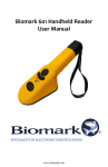
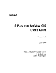
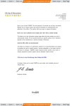
Superior Signal AccuTrak Model VPX-WR USER’S MANUAL Superior Signal Company LLC 2013 AccuTrak ® VPX-WR User’s Manual Superior Signal Company LLC CONTENTS QUICK GETTING STARTED _________________________________ 2 INTRODUCTION & GENERAL DESCRIPTION___________________ 3 PHYSICAL DESCRIPTION___________________________________ 4 OPERATION_______________________________________________ 5 AIRBORNE APPLICATIONS__________________________________ 7 Air or Gas Leaks (Pressure Leaks) Vacuum Leaks_____________________________________________ 9 NOSE CONE & ATTACHMENTS______________________________ 10 Touch Probe Waveguides_______________________________________________ 11 TOUCH PROBE APPLICATIONS______________________________ Steam Leaks (SteamTraps) Valves Internal Leaks in Hydraulic Systems___________________________ Mechanical Vibrations & Troubleshooting______________________ Bearing Inspection_________________________________________ 12 13 14 15 DATA COLLECTION & TRENDING____________________________ 16 ELECTRICAL APPLICATIONS________________________________ 17 Arcing Corona SOUND GENERATOR APPLICATIONS_________________________ 18 Tanks Enclosures CARE AND SERVICE_______________________________________ Battery Information Service Information 19 WARRANTY_______________________________________________ 20 SPECIFICATIONS__________________________________________ 21 GLOSSARY_______________________________________________ 22 NOTES___________________________________________________ 23 1 AccuTrak ® VPX-WR User’s Manual Superior Signal Company LLC QUICK GETTING STARTED To use the VPX-WR, put the headset on, with the cloth band over your head and the metal behind. The cloth band is adjustable, adjust the Velcro to fit your head properly. Align the red dots between the headset connector and the connector in the back of the instrument, and push them together. To remove the connector pull on the knurled sleeve on the connector. The same connector is used to charge the instrument and to output the Het. signal, when the charger or the output cable is plugged in to it. CAUTION ! Be VERY careful while wearing the headset around machinery. The headset is also a hearing protector attenuating the background noise which can make you think there is no machine motion. Additionally keep track of the cable between the VPX-WR and the headset so that it does not get caught in machinery parts. Turn the knob, slowly clockwise until it stops. The ON light will illuminate to show that the instrument is ON. At this setting the instrument is set now to maximum sensitivity & low level noise rejection, and it is ready to search for a leak. Point the front towards a suspected area and listen for any sound that resembles a leak. This sound will be like a hiss or a whistle in the beginning, and will turn into a soft clicking sound as the DND begins to capture the signal. Once the signal has been captured the dominant frequency will be heard in the headset. Leaks normally sound like a harsh hissing noise, which ascends in pitch as you approach the source. When you reach that point this sound will change into a tone or a number of different tones. It may be beneficial to you to test the sounds the VPX-WR produces using an air gun or an aerosol can like a lubricant or a deodorizing spray and just listen to it. CAUTION: If you are going to use an air gun to generate the sound, turn the sensitivity knob to 5% of its range of travel. Do not point the air stream directly in the instrument as you could damage it. Dropping pins on a table or spring-like metal pieces will familiarize you with how mechanical ultrasounds sound through the VPX-WR. When you use the VPX-WR in a tight space and you need to find leaks in hoses and tubing in manifolds, attach the horn restrictor to the horn of the VPX-WR and search for the leaks. The VPX-WR will take you to the exact point. If the suspected point is difficult to reach, use the plastic waveguide. You can make your own waveguides to fit particular needs you may have. See instructions at the section about waveguides. When the ON light starts flashing, you will need to charge the instrument within an hour. If the battery charge is not sufficient, the instrument will shut down. However since batteries recover it may come back only to shut down again. At this point you must charge it. We recommend that you leave the instrument plugged in the charger in between uses when you use it daily. 2 AccuTrak ® VPX-WR User’s Manual Superior Signal Company LLC INTRODUCTION & GENERAL DESCRIPTION Thank you for selecting the VPX-WR. You have invested in the most sophisticated and technologically advanced yet easy to use ultrasonic leak detector-inspection system available. We at Superior Signal have dedicated thousands of man-hours developing the VPX-WR, which has the only sensor in the world that, combines high sensitivity and hermeticity. The internal signal processing is a multi-patented process the DND and Heterodyne working together to assure the rejection of noise, identification of the leak signal and the translation to the audible range without the need for manual frequency tuning. Power is provided by a unique Nickel-Metal Hydride (NiMH) battery pack conditioned through a voltage regulator and supervised by a battery protector & condition indicator. The housing for all this technology is hard anodized aluminum for durability and longevity. The headset that accompanies the VPX-WR is the finest in its class and is used exclusively by military and commercial aviation. It provides sound attenuation while wearing a hard hat, muffling loud machinery noise, which can be hazardous to hearing. The instrument is packaged in a pressure-molded plastic carrying case, which can be secured using small key locks when necessary. This booklet contains information necessary to use and interpret sounds with your VPXWR. To help avoid any future frustration, please take the time to read and understand this information. Again, thank you. We are sure you will be pleased by your choice. 3 AccuTrak ® VPX-WR User’s Manual Superior Signal Company LLC PHYSICAL DESCRIPTION The VPX-WR is a cylindrical instrument with the sensor located in a sensor horn at one end of the instrument and the control and multifunction connector at the other. It is covered with a ground rubber grip to prevent the slippage of the instrument when the user has greasy hands. Sensor Threads The sensor horn shown in the figure above, left, houses the sensor and provides with the threads a mounting to attach the horn restrictor which is used to collimate the sound to narrow the field of view to help isolate the location of the leaks as well as to support the touch probe and the waveguides. The rear of the instrument has the control, the multi-pin connector and the power indicator. A steady light indicates the instrument is ON and when flashing indicates a low battery. The connector is used to charge the VPX-WR, to connect the headset and for the optional output cable. 4 AccuTrak ® VPX-WR User’s Manual Superior Signal Company LLC OPERATION Due to the high degree of sophistication in its circuitry, the operation of the VPX-WR is extremely simple. Automatic Frequency Tuning (DND), makes it possible to detect and interpret a broad range of ultrasound, while utilizing only one control. In addition to DND, a narrow frequency band of ultrasound is translated using heterodyning, and it functions just below the set point of the DND. The DND frees the user from having to tune the instrument for different frequencies, and it provides a distinctively different sound especially when searching for vacuum leaks. To use the VPX-WR, put the headset on, with the cloth band over your head and the metal behind. Align the red dots between the headset connector and the connector in the back of the instrument, and push them together. CAUTION ! Be VERY careful while wearing the headset around machinery. The headset is also a hearing protector attenuating the background noise which can make you think there is no machine motion. Additionally keep track of the cable between the VPX-WR and the headset so that it does not get caught in machinery parts. Turn the knob, slowly clockwise until it stops. The ON light will illuminate to show that the instrument is ON. At this setting the instrument is set now to maximum sensitivity & low level noise rejection, and it is ready to search for a leak. The graph below shows the way the DND works and the interaction of the two signal processors. The DND in addition to the automatic tuning acts like a dynamic noise discriminator by cutting off signals below its threshold. As you can see in the graph signals that exceed this level but then fall below it will be tracked for a few milliseconds to help you not lose the signal and get back to the correct location of the leak. 5 AccuTrak ® VPX-WR User’s Manual Superior Signal Company LLC Setting the control at 10 sets the instrument at maximum sensitivity and lowest rejection of noise/unwanted leaks, where at the other end is at the opposite. When you first walk in an unknown area set the control at 10 and listen. If there is a lot of background sound in the headset point the VPX-WR in another direction. If the sound stays the same, turn the control to the left, while you are pointing the instrument in the same direction as before and listen until the sound disappears. You have now set the DND at the level above the area noise. As you approach leaks now, which are stronger than the background noise, the DND will turn on and indicate them while the Het. is always indicating the background noise. Leave the vinyl protector on the horn to protect the edge from becoming deformed when bumping it. This may save the horn threads if you drop it. Do not abuse the control knob in any way, there is a spring loaded seal at the rear cap of the instrument to prevent contaminants from entering the housing and it can deform when abused. When not in use cover the headset and charger plugs with their orange covers. The covers protect the connectors from contaminants. To clean the horn and the threads you can use a shop cloth with a little alcohol or glass cleaner. Lubricate the threads and the horn after cleaning with silicon grease. Be very gentle with the sensor. Similarly clean the Nose Cone and its threads. Inspect the O-Ring for cracks. If the O-Ring is cracked order one from Superior Signal or buy one locally. The O-ring part number is a Parker # 2-025, 70 durometer. 6 AccuTrak ® VPX-WR User’s Manual Superior Signal Company LLC AIRBORNE APPLICATIONS AIR OR GAS LEAKS Pressurized air leaks (gas) generate high intensity ultrasound. In places where no other noise is present, sonic or ultrasonic, finding the exact location of the leak is relatively easy. This is because ultrasound is like a microwave and microwaves propagate in straight lines. In loud industrial environments such as a mechanical room for a compressor, a leak might appear to originate from many spots. The sound reflects off walls, the ceiling and many other surfaces as it normally does with echo. None of these reflections are as strong as the true source of the sound, the leak. The DND incorporated into the VPX-WR makes it extremely easy to locate these strong signals while eliminating the weaker ones. Begin by turning the control clockwise until it stops. You are set now at full sensitivity for the heterodyne block and at the lowest detection threshold for the DND. If you are in an area with extensive background noise you will hear a lot of sound in the headset. Stand a few feet back from the general area you will be testing, and turn the sensitivity adjustment slowly to the left until the background noise disappears or is reduced. You can now go to work listening for leaks. The DND in the VPX-WR will only translate to the headset those sounds which are strong enough to peak above the "noise floor" which you have set with the control. Below this "noise floor" that you've set, and for a frequency band of ±4kHz around 38kHz the heterodyne section will give you an indication that there may be something there to check as you pass a point on the system you are checking. If a faint sound or even a change in the background noise is detected, turn the control a little clockwise. Depending on the cause of the sound the DND will kick in and confirm that you are on to something, otherwise it will remain quiet. The VPX-WR is capable of reproducing even the minutest variation in the level of the sound so you can decide which direction to follow. The leak can be located in seconds by a simple process of elimination, including approaching the sound from different directions. Leaks found in open installations, like trucks or railroad cars, pose little problems in locating them. Problem leaks are the ones in tight spaces, around engines and installations where reflections can be almost as strong as the source itself. At times the leak sound competes with other ultrasonic sources, like bearings and internal engine noises. In cases like these, turn the knob to the left to reduce the sensitivity of the instrument, thus setting a new threshold for the minimum strength that a leak must have to be detected. This way you eliminate most of the small leaks, or the reflections, and you can concentrate on the major ones. If you are searching for leaks from a large distance the size of the leak and the atmospheric conditions determine the detection distance. The figure on the right shows the attenuation (weakening) of sound from a leak as a function of distance from the leak point and humidity. 7 AccuTrak ® VPX-WR User’s Manual Superior Signal Company LLC Maximum sensitivity is normally used in locating very small leaks or leaks from far away. If you find that too much background sound is coming in at the minimum sensitivity setting of the instrument, the front must be muffled. The nose cone can do this very well. You can use the nose cone alone, or with the flexible wave guide (a piece of PVC or Nylon tubing that fits in its front). This will extend the reach of your instrument to very tight places. If you are in a very loud area searching for small leaks you should shield or change the direction you are using the VPX-WR if background noise “floods” the instrument. Loud areas contain ultrasonic sound which is unwanted noise. This noise is generated by leaks and other processes but it may not be what you want to find at the point where you are but they may be leaks that you have not found yet. Physically isolating this noise using the accessories and sometimes a piece of carton can help you use the VPX-WR at a higher sensitivity to locate very small leaks in loud areas. When you are searching for very low volume leaks in the order of 0.2 SCFH or less, the orifice is a very important factor in determining the sound strength. If the orifice is "large" the flow may not be turbulent thus generating very little sound. In these cases when you know by other means that there is a leak, install the nose cone and move the instrument very slowly around the suspect areas, along pipes or seams but with a tight zigzag along the path. This technique will help convert laminar flows into a shock wave when the gas hits the edge of the fitting of the nose cone. Generated ultrasonic sound will be detected by the VPX-WR and show the leak. Use a spray bottle and spray water on the suspected area if the system permits it. Air flowing through the water will generate bubbles which burst and create ultrasonic shock waves making it easier to detect. Another technique that may be applied, conditions permitting, is to cover a suspect spot with your finger. Do not rub because your finger can make sounds too. Just cover an area for five seconds then let it go. (This simply traps whatever gas or air is in the system and then lets it go, doing the same thing as squeezing a bottle while holding it closed and letting it open.) The sudden release again creates a shock wave that can be detected. Leaks originating from cuts or holes in membranes, or other rubber type materials, are very difficult to detect. The elasticity of the material makes the orifice smooth and reduces the turbulence to very low values. Here again, the zigzag technique must be used to find the leak point. Ultrasonic leak detectors will not indicate a leak if there is no flow producing sound when you check for it. High concentrations of fuel fumes in a storage room, for example, might have been caused by a leak when the temperature was high. Leaks of this nature are called static leaks, while leaks that are caused in pressurized systems, (positive or negative) are called dynamic leaks. Dynamic leaks are the leaks that do make sound and can be found with the VPX-WR. Make sure that you fully understand this important distinction. When searching for leaks from combustible or dangerous gasses you should also use other types of gas detectors like sniffers, which check for concentrations in the atmosphere. WARNING ! Ultrasonic detectors will not indicate a leak if there is no turbulent flow producing sound when you check it. If you suspect a toxic gas, combustible gas, or other dangerous gas leak, but you cannot find it with the VPX-WR, do not assume that it does not exist, as it may not be turbulent at the time when you check for it. Use another method as verification that there is no leaking dangerous gas present. 8 AccuTrak ® VPX-WR User’s Manual Superior Signal Company LLC VACUUM LEAKS Searching for vacuum leaks is fundamentally the same as with air leaks, with one difference: the sound generated at the leak is stronger towards the inside of the system that generates it. Fortunately, that remaining on the outside is strong enough to create a signal that can be picked up in some cases, several feet from the leak. Remember that the size and the shape of the orifice affect the intensity of the generated sound as significantly as the amount of air or gas rushing through it. Therefore judgments on the actual size of the leak should be reserved until a more thorough inspection is made. The VPX-WR helps you find the location of the leak, and by reproducing the sound fluctuations, it gives you an indication of its rate. Vacuum leaks sound the same as air leaks. When checking for vacuum leaks in intake manifolds of automobile engines, much sound activity is created from valves and other components. These sounds differ from leaks because they are rhythmic, i.e. they follow the engine motion, unlike leaks, which stay almost constant. The same is true with mechanical vacuum pumps. The nose cone may be necessary to help isolate other noises or to identify closely spaced leaks. If the system can be pressurized with nitrogen or any other gas, you will find its leaks faster with only one bar of pressure, (14.7 PSI) than trying to do the same with vacuum. Simply the sound is stronger on the outside of the system. A technique that could be used, if the system permits, is a spray of distilled water. Using a spray bottle to wet the suspect areas will increase the sensitivity of the detection. The droplets, as they enter the system, explode and generate shock waves that the VPX-WR can detect. You may use alcohol or acetone, but the choice is yours and depends on system requirements and safety. TIPS ON USE: Move the instrument slowly around the suspect areas. Use the nose cone with the plastic waveguide. Use pressure if the system permits it, it is more efficient. Use the touch probe. Be patient and plan your approach. Eliminate section by section the leak points by isolating areas. 9 AccuTrak ® VPX-WR User’s Manual Superior Signal Company LLC NOSE CONE & ATTACHMENTS INSERTING THE NOSE CONE ON THE HORN Remove the vinyl horn cover, place the Nose Cone at the front of the VPX-WR and make sure that the threads are engaged properly. Turn the Nose Cone slowly until it reaches the ORing and stops. Slightly tighten but DO NOT OVERTIGHTEN! To attach the touch-probe or the wave guide, simply slide it into the fitting at the tip of the Nose Cone, and tighten the nut until it is finger tight. INSERTING THE TOUCH PROBE IN THE NOSE CONE Insert the touch probe in the fitting in the horn restrictor and tighten the knurled nut. This nut must not be loose because it will generate noise in the measurement. Below is a sectional view of the probe-restrictor-horn of the VPX-WR. If the Nose Cone, or the knurled nut is not tight enough, the touch probe will not transfer the sound from the measurement point to the sensor. Conversely, if you tighten the Nose Cone too much or the set screw is loose it will overload the sensor, and in extreme cases of the screw being out, it may damage the sensor. It is important to note that the adjusting screw of the probe must touch the sensor to transfer the sound propagating in the rod. 10 AccuTrak ® VPX-WR User’s Manual Superior Signal Company LLC WAVEGUIDES Waveguides are tubes that carry the sound from a source point, such as a leak point, to the sensor of the VPX-WR. We have designed the VPX-WR so that standard 1/4” tubing can be used to make waveguides to fit the user’s needs. This is very useful in pneumatic systems found in tight spaces like the tail or nose of aircraft or industrial control panels. To make your own waveguide copy the one supplied. You will need a nut a ferrule set and an O-Ring or a piece of tape. The O-Ring is to keep the nut from falling. We use Swagelok brand components but you can use other brands that fit Swagelok. See the figure below for the alignment. All 1/4” tubing type fittings from Swagelok will fit into the Nose Cone. You can use tubing up to 15’ long (5m). Longer tubing lengths attenuate the sound. The easiest way to make a wave guide is to use the nose cone. Insert the nut and the two ferrule pieces on the tubing as shown in the following figure, then pass them through the female fitting in the nose cone and screw the nut finger tight. Use a 1/2” wrench on the fitting and 9/16” on the nut and turn the nut one full turn. Do not exceed the 0.23” length of the tube from the face of the nose cone, you will damage the sensor. The tubing material can be plastic, copper, steel etc. If you use metals ensure the nose cone is tight on the horn before inserting to minimize thread loading and potential stripping. Plastic is available from Superior Signal in precut pieces of 6”, 18”, and in bulk as well as the fittings, ferrules and O-rings. 11 AccuTrak ® VPX-WR User’s Manual Superior Signal Company LLC TOUCH PROBE APPLICATIONS (Touch Probe must be properly installed) STEAM LEAKS Steam leaks and faulty steam traps can cost a facility hundreds of thousands of dollars in energy loss and maintenance costs. These problems can be eliminated using the VPX-WR. If the leak is within a device, like a steam trap or a valve, the VPX-WR will indicate the leak by detecting the sound it generates. The sound of a leaky trap or valve will be the strongest at the point of the leak and it will be like a whistle that constantly blows. You can use the sensitivity adjustment to locate this point. Start with high sensitivity and touch the feed side of the trap and then reduce the sensitivity, until you lose the sound. You have effectively set the decision threshold and the DND will eliminate extraneous pipe sounds and let you concentrate on the item being tested. Touch here first To determine the condition of a steam trap, sample the sound before and After the trap. When the trap is closed, it should not make any sound. If the trap is continuously blowing steam, it will be very obvious by the constant rushing sound within the trap. There are a number of different types of traps, which make different sounds during normal operation. Thermostatic traps are the easiest to test since they make a lot of noise when they flow or leak. It is easy to tell when the trap is cycling, stuck or blowing steam. Inverted bucket or the float type are sometimes challenging but checking the pipes in/out may be the best way to determine if they are stuck open. TIPS ON USE: Make sure that you understand how the particular trap or valve that you are testing works. Do not confuse normal cycling sounds with problems. When touching the VPX-WR to a pipe or a valve, do not rub it. Just apply enough pressure to make a good contact. Bear in mind that sound travels through pipes, and what you are hearing may be coming from elsewhere. To determine if this is the case, touch the pipe at other locations to see if the sound intensity increases or decreases. Use the sensitivity control to eliminate other sounds. If at the lowest setting you are still getting too much sound, then turn the Nose Cone back to eliminate the contact between the sensor and the probe and repeat your tests. Use a thermometer, IR or other and check the temperature of the trap. Lower temperatures mean flooded or leaking valves. 12 AccuTrak ® VPX-WR User’s Manual Superior Signal Company LLC INTERNAL LEAKS IN HYDRAULIC SYSTEMS External leaks in hydraulic systems are usually easy to find. Following the fluid to the source is not a difficult task. Internal leaks, however, can be very tricky. The VPX-WR can be used to listen to the sound of the fluid internally and to indicate the fault. Generally when checking for an internal leak in a cylinder, the side that is leaking can be easily found. Valves of all kinds, even steam or water, can be checked without guessing about their condition. Touch here Typical Proportional Hydraulic Valve To carry out this test use the instrument as if you were searching for an air leak. The VPXWR can listen to the sound of the hydraulic fluid as it flows through a cut on the seal of a cylinder, or the spool of a valve. When testing hydraulics, make sure that there is no cavitation in the system because it generates added sound and can be detrimental on the system itself. This extra noise background may make it more difficult to find the leak. Again, pressurizing the system with nitrogen before fluid is introduced will indicate if there are any gross leaks. This can save much time when troubleshooting. For Internal leaks use the touch probe and proceed as you check a valve or steam trap. For External leaks the VPX-WR is the only instrument in the world that can track a hydraulic fluid leak to the source, and get wet by it without getting damaged or having its performance affected. TIPS ON USE: If you have a cylinder that slowly loses its position, listen around it to determine where the sound is the strongest. Mark the spot so the cylinder can be inspected after disassembly for marks and scratches on the inside. The dead center of the spool in a valve can be set by listening to the fluid sound while adjusting it. If you get hydraulic oil on the instrument, wipe most of it with a shop towel, then use a detergent solution on another towel to clean the rest. 13 AccuTrak ® VPX-WR User’s Manual Superior Signal Company LLC MECHANICAL VIBRATIONS & TROUBLESHOOTING The most common mechanical failure is a broken or seized bearing. However this type of failure does not happen instantly under normal conditions. When bearings begin to fail, their sound changes. This sound can be detected with the VPX-WR by touching the bearing housing with the instrument and listening for abnormal sounds. You need to know "healthy sounds" from previous experience so you can recognize the abnormal conditions. Periodic maintenance can prevent major disasters in both the machinery and down time and will teach you the sound patterns. The DND should be at a high threshold since it will distort the harmonic content of the sound because it is a digital process. However the Het-Block will faithfully reproduce the sound. The signal output from the VPX-WR is only from the Het-Block and when coupled to a spectrum analyzer or a vibration analyzer will show the ultrasonic activity of the bearing, the headset contains both the DND and Het. This sound can be used to determine the lubrication condition of a bearing. Lubricating and listening at the same time will tell you when to stop since the sound should decrease as you inject grease; when slightly increases you should stop. TIPS ON USE: The success of this technique relies on regular tests by the same person. People hear different things even if the sound is the same. When doing this test, listen when normal conditions exist also. This will set the background for future tests. Any change in the sound pattern will be easier to identify. Use an IR thermometer and check the temperature of the pillow block or the bearing housing before and after lubricating. Correlate the sound from the VPX-WR with the temperature and the number of shots from the grease gun. When the bearing is properly lubricated both the sound and the temperature will decrease. Record the sound with a tape or digital recorder and download it to a computer for analysis. Adobe Audition (Cool Edit) is a good entry level product to use and analyze the sounds. More sophisticated products like National Instruments sound and vibration modules can be used to analyze sounds in more detail. http://store.adobe.com/products/audition/overview.html http://www.ni.com/analysis/sound/toolset.htm 14 AccuTrak ® VPX-WR User’s Manual Superior Signal Company LLC BEARING INSPECTION To inspect and trend bearings the VPX-WR can be connected to a vibration analyzer to view the high frequency sounds generated in bearings of all types especially babbit type which have no rolling elements. Babbit type bearings are very difficult to trend with vibration analysis, using accelerometers, because they do not “move” like roller and ball bearings do. The friction generated within a bearing-shaft system when it loses lubrication, generates ultrasound which is then translated by the Het. block and sent to the output of the VPX-WR. Please refer to your vibration analyzer’s user manual for instructions as to how to configure its input parameters for a voltage input. The maximum output voltage of the VPX-WR is 750 mVpp The figure below is a screen capture from a vibration analyzer connected to the output of the VPX-WR testing a motor-gearbox combination. The spectra shown are from 38 kHz to 39 kHz and the RMS Average is the signal level. The large peak shown at 602.6 is from 38kHz+602.6 Hz = 38.602 kHz. 38 kHz is the internal Het. reference. Trending these peaks will indicate problems such as chipped gear teeth where the RMS average will indicate the overall wear. 15 AccuTrak ® VPX-WR User’s Manual Superior Signal Company LLC DATA COLLECTION AND TRENDING The VPX-WR provides the user with a narrow band signal that is used to detect and record ultrasonic sounds in the range of 34 to 42 kHz. Use the special cable option that converts the Multi-pin plug to a BNC. Plug the BNC to a spectrum or a vibration analyzer to record the waveform. Set the VPX-WR control to maximum. Set the analyzer attenuation at midrange. Take a reading. If the waveform fills the screen completely, increase the attenuation of the analyzer. (Less sensitive). If the waveform is barely visible decrease the attenuation, and repeat this process until you learn the settings for the analyzer. In certain situations you may need to decrease the sensitivity of the VPX-WR if there is strong background noise. Start testing new machines or new bearings first. This will help you establish a base line in the amplitude and the nature of the harmonics present at the test point. Periodic tests at the same location will show the difference between the normal condition and a developing fault. New frequencies that were not present in previous tests will appear, the amplitude of existing ones will change. Early frictional faults will appear as high frequencies. The amplitude of the output signal is 0 to 750 mV, and the frequency range is 0 to 4 kHz. The actual ultrasonic frequency is 38 kHz plus (or minus) the observed translated frequency. This means that if you observe a peak in your analyzer at 1600 Hz it comes from a 38+1.6=39.6 kHz source. (or 38-1.6=36.4 kHz). TIPS ON USE: Use Excel or a similar spreadsheet software tool to graph your results. Excel has an extensive graphing capability. If you need more graphing power including curve fitting use Axum. 16 AccuTrak ® VPX-WR User’s Manual Superior Signal Company LLC ELECTRICAL INSPECTION ARCING Arcing is a very catastrophic phenomenon that occurs in relays and contactors. Arcing sounds like a constant buzzing similar to the sound of frying potatoes. To test suspected equipment, use the plastic wave guide and cut it or make a new one with the length you need and test around the contactors and relays. CORONA Corona is a form of plasma current flow that is found around higher voltages like transmission lines. It is invisible in the visible spectrum, however under certain conditions a bluish glow can be seen at dusk. Thermography can detect this phenomenon but when it is coupled to ultrasonic inspection its presence will be confirmed and action must be taken fast. The sound of corona is similar to arcing, but with popping sounds in the spectrum. CAUTION ! Observe ALL safety rules for the voltage you will be close to. Make sure Arcing CANNOT take place from the parts you test to the VPX-WR, or to YOU. 17 AccuTrak ® VPX-WR User’s Manual Superior Signal Company LLC SOUND GENERATOR APPLICATIONS DESCRIPTION The Sound Generator and the VPX-WR form a non-invasive leak detection system capable of finding leaks in enclosures, such as tanks, vessels, automobiles, buildings or any other area that needs to be leak-free. The SG-2 is an ultrasonic sound source of miniature size that is used to "pressurize" rooms and enclosures with its sound. This sound is above the human hearing range, and cannot be heard. It can penetrate through minute cracks, even ones that are not directly behind the leak point, and exit through it. It can thus trace the path a gas, or a liquid, will take to cause a leak. The VPX-WR receives the ultrasonic sound that escapes from the leak point, processes it and displays its strength. The bigger the leak is, the higher the volume in the headset. OPERATION To use the system, the sound generator must be turned ON. Simply push the ON button on top once and the red LED will illuminate to indicate that it is ON. To turn it OFF, push the same button again and the red LED will go off. Place the SG-2 in a tank, hatch, aircraft, walk-in cooler etc, go to the other side and close the door or window or other cover and search with the VPX-WR to find where you can hear sound, just like as if you are searching for air leaks. TIPS ON USE: To prevent standing waves in a tank select the burst mode. Be sure the area to be tested is dry as capillary tension in the water may block the passage of sound. To test an enclosure, turn the Sound Generator ON and place it inside. Seal the enclosure, and turn the VPX-WR ON. Start from a low sensitivity and check if you can hear any sound. If you can, check the area of interest and note the points where the intensity is high. If you cannot hear any sound, increase the sensitivity and repeat the previous step. Use Post-it-Notes to stick at points where you have located the sound and write the perceived intensity or use different colors for different intensities. When you finish, step back and observe the pattern of the notes. It will show you where problems might be concentrated, like in the case of a warped door. Thin tanks may resonate, creating a false leak signal on the surface. If this happens put a small piece of open cell foam (like the type in the case) in the nose of the generator to reduce its power. 18 AccuTrak ® VPX-WR User’s Manual Superior Signal Company LLC CARE AND SERVICE CARE VPX-WR's hard anodized case resists scratches and corrosion. It is made from an aluminum alloy; therefore, prolonged exposure to acids or bases may alter the finish. If you find yourself working in damp areas or the instrument is exposed to chemical agents that corrode, make sure that you wipe it clean with a soft cloth and window cleaner. Be very gentle around the front of the instrument so that the sensor is not damaged. Periodically, use silicone grease on the case to bring back its original luster. Battery Information: The VPX-WR is powered by a unique NiMH battery pack. It is conditioned through a voltage regulator which means the instrument’s performance will not degrade as the battery life decreases. The power indicator will flash when there is approximately 1 hour of use remaining. At the end of the battery charge the battery supervisor will shut the instrument down. This may happen during the detection of a leak, which will require more power to be delivered to the headset thus causing the instrument to cycle ON-OFF until it is completely discharged. When this cycling condition occurs recharge it. A fully charged battery should allow 10 to 12 hours of uninterrupted use, and it will take approximately 16 hours to fully charge. The battery pack should give you at least two years of service when the VPX-WR is used daily as above. If you feel the battery charge does not last as long as it used to, please contact Superior Signal for service. NOTE: The VPX-WR Battery Pack is a sealed unit inside the instrument. Do NOT try to open the instrument to change the pack yourself. Doing so may damage the instrument beyond repair and it will void your warranty. SERVICE If you need service, please call Superior Signal Company and request an RMA number and instructions to return the instrument. Global Telephone number: +1-732-251-0800 E-Mail: [email protected] Web Address: www.SuperiorSignal.com 19 AccuTrak ® VPX-WR User’s Manual Superior Signal Company LLC Superior AccuTrak® Warranty ® Superior AccuTrak products are warranted unconditionally for 30 days, and may be returned for any reason during that time for a full refund of the purchase price. Instruments must be returned with all supplied components and accessories in “like new” condition. Note: Shipping charges and return shipping are not covered under any warranty. Please contact us for instructions prior to returning any product for any reason. ® Superior AccuTrak products are additionally warranted for 1 year to be free of manufacturing defects that adversely affect performance. Warranty does not cover any shipping charges to and/or from Superior. Should an instrument fail within the 1 year warranty period, the unit will be repaired or replaced, provided the instrument has not been tampered with or abused. All determinations are at the sole discretion of Superior Signal Company LLC. A minimum diagnosis fee will apply to warranty returns which are determined to have no flaws. Please contact us for instructions prior to returning any product for any reason. All warranty eligibility determinations are at the sole discretion of Superior Signal Company LLC. Maximum liability under any circumstance shall be limited to replacement of unsatisfactory product. Recommendations and product information are believed to be accurate, but the furnishing of it does not constitute the making of a good process warranty of Seller. Superior warrants that this product conforms to the product description contained in this literature. Superior Signal Company LLC makes no other warranty, whether expressed or implied, including warranties of merchantability or of fitness for a particular purpose or application. No statements or recommendations contained herein are to be construed as inducements to infringe any relevant patent, now or hereafter in existence. Superior neither assumes nor authorizes any representatives or other person to assume for it any obligation of liability other than such as expressly set forth herein. Under no circumstances shall Superior Signal Company LLC be liable for incidental, consequential or other damages from any alleged negligence, breach of warranty, strict liability or any other theory, arising out of the use or handling of this product. For Warranty questions, claims or assistance please contact us directly: Phone: 732-251-0800 Fax: 732-251-9442 E-Mail: [email protected] For more information please see our website: www.SuperiorSignal.com 20 AccuTrak ® VPX-WR User’s Manual Superior Signal Company LLC SPECIFICATIONS for VPX-WR Performance Sensitivity: Frequency Range, DND: Frequency Selection: Frequency Range, Het: -74 dB/V/μbar 20 kHz to 100 kHz Automatic, DND 34 kHz to 42 kHz Power Requirements Battery: Average Charge Duration: Average Charging Time: Low Battery Indicator: Rechargeable NiMH 8 hours of continuous use 4 hours Flashing LED when 1 hour of use remains Physical Construction, Hard Anodized Aluminum Housing with padded grip Dimensions: Outer Diameter: Length: Weight: Shipping Weight: Cylindrical 1.75" (44.5mm) 10.254" (260mm) 14 oz. (397gr.) 8 lbs. Headset: High quality, Noise attenuating for use with a hard hat Carrying Case: Pressure molded plastic, compartmentalized, with locks Accessories: Contact Probe, Flexible Wave Guide, Nose Cone, Charger Specifications are subject to change without notice 21 AccuTrak ® VPX-WR User’s Manual Superior Signal Company LLC GLOSSARY DND Automatic Frequency Tuning Collimate: To make parallel Dynamic leak: A leak caused by active pressure Hermeticity: Air tightness Heterodyning: A process where two signals are mixed (multiplied) to produce two others which are their sum and difference in frequency. Laminar flow: Smooth flow where the fluid is in non-mixed layers Leak rate: The amount of gas, in cubic feet per minute or liters per minute Noise: Any unwanted signal competing with the one of interest Reynolds number: An index which shows if the flow is turbulent or not. (Numbers under 2000 are laminar and over 3000 turbulent) SCFM / SCFH: Standard cubic feet per minute or per hour. These are units of flow. Sonic sound: Sound humans can hear Static leak: A leak caused by low pressure that does not generate sound Turbulent flow: Random, mixed flow Ultrasonic sound: Sounds above the human hearing range Viscosity: The internal friction of a fluid or gas. The higher the viscosity the slower the fluid moves 22 AccuTrak ® VPX-WR User’s Manual Superior Signal Company LLC NOTES 23