1
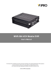
Mobile DVR (MDR)
User Manual
1
1. Overview
1.1 Introduction
Mobile DVR adopt highly integrated H.264 ASIC, using the SD card or hard disk as a video
storage medium. The system is with strong anti-vibration capability. Sealed housing is suitable for
use in vehicle environment.
In addition to integrated vehicle status monitor, MDVR support built-in GPS, 3G and WIFI
modules.
The MDVR system support CMS software for PC and mobile phones. The playback software of
MDR achieve multi-channel playback with GPS ,speed information etc.
MDVR is widely used in buses, taxis, police cars, law enforcement vehicles, and other various
types of vehicles
1.2 Features
H.264 Compression, Record Resolution Up to D1
Dual Stream for Recording and Network transmit
Support Hard disk / SD card recording,
SD card and Network Backup
6-36V power input
Vent-free enclosure design
2
2. Installation Notes
MDR is not waterproof; please install it in dry environment, to avoid the wet, drip, sprinkler
and other places.
MDR should be installed in the vehicle ventilated area, and to ensure that the vehicle away
from the heat source. Should not be installed in a closed space.
To extend life of MDR, if possible, installed MDR at weaker vibration space in vehicles,
such as space behind the driver
Topping red gum between all screws and nuts or fixed components to prevent loosening.
Comply with all regulatory requirements for electronic products during the installation and
operation of MDR, as well as vehicles and other connected equipment.
MDR DC power input range is 6V to 36V, please be careful not to take anti-polarity, the
output can not be shorted. Please note that the power supply capacity of the power cord.
MDR power output is 12V, only to be used to power the allowing equipment; power off the
MDR before connecting with external device
Handle and transfer MDR with care. Fall May cause internal hard drive and other precision
parts damage
3
3. Device Interface description (sample)
3.1 Front Panel Description
Indicator Description
Indicator
IR
REC
3G
PWR
SD
GPS
STAT
Function
IR
Record
status
3G
status
Power
SD
status
GPS
status
Run
status
Interface Function Description
Video Out
Front panel video output (optional)
SD1
SD card slot
SD2
SD card slot
IR
Infrared receiver window
LOCK
SD card tray lock
SIM
SIM card slot (built-in 3G models have this interface)
3.2 Rear Panel Description
4
AV1-AV4
Camera connector 1-4, including 12V power supply output, video input,
audio input
AV_out
Monitor connector, including 12V power supply output, video output, audio
output
PWR_IN
Power input connector, including power input, GND, ACC, Door
signals
I/O
IO connectors:4 SENSOR_IN ,1 SIN,1GND,2 ALARM_OUT,1 RS 232,
1 RS 485
NET
Ethernet port
GPS
GPS Antenna Interface (optional)
3G
Mobile Communication Module Antenna Interface (optional)
WLAN antenna interface (optional)
WiFi
3.2.1 Camera connector
AV 1-4 is defined as follows
Audio
In
GND
12V
OUT
Video
in
3.2.2 Monitor Connector
AV_OUT is defined as follows
Audio
Out
GND
12V
OUT
Video
Out
3.2.3 Power in Cable
Power in Cable Defined as follow
5
DC
PWR_IN +
DC
PWR_IN -
GND
DC
PWR_IN +
DC
PWR_IN -
ACC
3.2.4 I/O combination Cable
I/O port, includes vehicle status interface, RS232, RS485, RS422, alarm input and
output , Vehicle status interface 2-6 also can be used as active alarm input。Signal is
defined as follow:
6
Speed sensor input connection:
+24V
Braking LED
Braking
Sensor input
Alarm output connection:
MDVR Alarm output
24V
4.Operating
4.1 Remote Controller
7
MDVR product panel has no direct control button on the need to use the remote control
with the operation.
Remote control buttons and functions are introduced:
A numeric keypad:
[0-9] key: setting status, digital input keys used to select the numbers. 1,2,3,4
keys for switching between channels in the playback and preview
(2) Set the menu navigation:
, : Under the cursor moving key;
, : Left and right cursor direction keys;
[ENTER]: In the set state, said the selection and preservation;
Other function keys as follows:
Shutdown
LOGIN
INFO
On/Off button,Shutdown when the MDR is on,Turn on when the
MDR is off
When MDVR have set password, press the LOGIN to enter the
password.
Noted the system without restore and factory default function,
please do remember the password;
If the MDVR without password, press LOGIN could visit the main
menu;
Information, press INFO to quickly view the configuration
information of GPS, 3G and other modules;
Press the key switch between no split and 4 split,Press 【1】—【4】
Layout
to switch to Zoom the image to full screen
switch,
RTURN /
Return to upper level menu. exit the setup menu to the monitor
screen Finally;
CANCEL
Pause when playback,press STEP to play in frame.
PAUSE /
STEP
Jump to a specified time to play during the playbak
GOTO
PLAY
PLAY
Fast forward,Switch between 2/4/8/16x
FWD
Fast rewind,Switch between 2/4/8/16x
REW
Stop
STOP
manual record
RECORD
8
Slow motion key, switch between 1/2, 1/4, 1/8;
NEXT
4.2.1 Login
The default login username is 000000, password is 122222.
4.2.2 Menu
Menu and corresponding function:
Video search
search the record file from hard disk /SD card to playback
Record setting
set the video、 audio parameters,and
System setting
Set the alarm, PTZ, time, network
System
Information
Display the serial number, version information, MAC address..
etc system information
Vehicle
information
set the vehicle license plate number, timer switch on/off,
WIFI..etc
Display Settings
Set the monitor screen and the content of the video data,
including the display of information, regional, color, volume, etc
9
recording mode
Password
management
Set the machine password
Exit
exit the menu interface, returns to direct the monitoring interface
4.2.3. The preview interface
Figure With card video recording and without card prompts on the monitor screen
Straight through the preview screen will display the message of the state of equipment
and each channel state, the meaning of the message is as follows:
2011-8 - 31 09:54:34
shows the system time
CH1/2/3/4
channel name
● REC
Said video recording is in progress
NO DISK
that there is no video recording
The GPS: NO ...
when you press the remote control "INFO" key quickly to
display system information, such as GPS and other state
10
4.2.4 video retrieval
Figure 11 video retrieval map
And video retrieval interface provide to retrieval, playback and backup video files stored in
the disk
Retrieval methods can choose to fast and precise time positioning, time period recording
status browsing and detailed video file browsing.
Instructions:
1. Go to the video search interface, click Search - file list directly to the current time
by default, you can playback or read the video file.
2. Fast and precise positioning retrieval methods:
Enter the date and time of the recoding video you want to play (defaults as
the last minute of the video search interface).
Recording mode color-coded, red for alarm recording time, green for
ordinary video file recording time, no colors represent the time period has
no any recording files.
Month recording status in days mode, daily recording in half-an-hour mode.
Select the recording video in recording status in the day, then can play the
video recorded in that period directly.
3.
Detailed video recording file browse and retrieval:
If the retrieved time period recording, Click the <detailed file> Button to open
a browsing interface of the detailed files, the list shows the recording video
by date selected, then you can flip pages to browse .
Display content, including video files, start time, end time, file size, video type.
Screening by record type file.
You can select the video file, and select the video files are backed
up.
4.2.5 video playback instructions
A single-channel playback and multi-channel synchronous playback in two ways.
2 player mode control, including:
11
Select normal playback, single frame playback, slow motion, fast forward and
rewind.
Adjust the volume.
(1) Fast forward: 2X (2x)-16X (16x)
(2) Rewind: 2X (1 minutes back)-16X (Back 8 minutes)
(3) jump (GOTO): pop-up input box to display the change to play the beginning of
the file (start) to end (end) time scope, the time edit box is set to jump time (must between
start and end time), exit edit box, select OK.>, OK!
Such as:
Start: [02:00:00] end: [02:30:00]
Editor [02:18:00] to determine after the jump to the time to play around
[02:18:00]
5. 3G network & platform using
5.1 3G network instructions
1)Confirming which Telecom operator you use ,China Telecom, China Unicom or China
Telecom?
2)Inserting the 3G card (SIM card),make sure the 3G card balance)
3)Checking the 3G antenna is connected properly
4)The product’s setting which need reconfirming
Main Menu -Recording Setting- Small stream configuration. The remote 3G watching‘s
channel code need setting as open. The user could change different channels resolution
(CIF or QCIF) and frame rate based on different conditions
12
Main Menu - Vehicle management- Wireless internet access function need to set as open
Main Menu - vehicle management - basic settings, need to confirm with the supplier
whether the vehicle number (such as 04017 ) assigned correctly
Main page - Settings - Network setting -CMS configuration, confirm with the supplier
whether the center IP address and IP port number are correct
5)Confirm whether the device is dial successfully
13
Main page - vehicle management - wireless settings, check the wireless status if the IP
display normally. If the IP address is blank, it means unsuccessfully setting; if IP address
is 172.45.144.251, it means successfully setting
5.2 3G platform using instruction
1)installing client software
New client downloading address:http://210.22.8.99/download.html, or ask the supplier to
provide, Pls press Next STEP to install
2)Sign in
14
Ask the Supplier for administrator and password, the server and port
After a successful login , Double-click the device channel you would like
5.3 3G Checking
1)Checking if it dials successfully
15
As above means successful
As above means fail
2)check the server IP (such as 116.255.233.211)
If all work well. It means OK
16