1
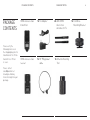
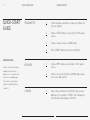
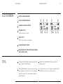
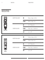
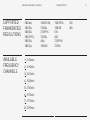
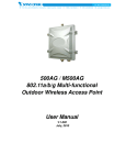
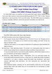
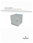
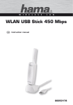
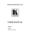
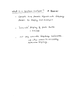
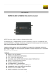
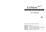
USER MANUAL Check our knowledge base at www.paralinx.net/support Copyright 2015 Paralinx LLC All Rights Reserved TABLE OF CONTENTS PARALINX TRITON 1 Important Notice 10 LCD Screen 2 Safety Instructions 11 Indicators 3 Overview 12 Specifications 4 Package Contents 14 Troubleshooting 5 Transmitter 16 Available Frequency Channels 7 Receiver 17 Triton Accessories 9 Quick-Start Guide 1 IMPORTANT NOTICE IMPORTANT NOTICE PARALINX TRITON Paralinx reserves the right to make corrections, modifications, enhancements, improvements, and other changes to its products and services at any time and to discontinue any product or service without notice. Customers should obtain the latest relevant information before placing orders and should verify that such information is current and complete. All products are sold subject to Paralinx’s terms and conditions of sale supplied at the time of order acknowledgment. machine, or process in which Paralinx products or services are used. Information published by Paralinx regarding third-party products or services does not constitute a license from Paralinx to use such products or services or a warranty or endorsement thereof. Use of such information may require a license from a third party under the patents or other intellectual property of the third party, or a license from Paralinx under the patents or other intellectual property of Paralinx. Paralinx warrants performance of its hardware products to the specifications applicable at the time of sale in accordance with Paralinx’s standard warranty. Testing and other quality control techniques are used to the extent Paralinx deems necessary to support this warranty. Except where mandated by government requirements, testing of all parameters of each product is not necessarily performed. Reproduction of information in Paralinx data books or data sheets is permissible only if reproduction is without alteration and is accompanied by all associated warranties, conditions, limitations, and notices. Reproduction of this information with alteration is an unfair and deceptive business practice. Paralinx is not responsible or liable for such altered documentation. Paralinx assumes no liability for applications assistance or customer product design. Customers are responsible for their products and applications using Paralinx components. To minimize the risks associated with customer products and applications, customers should provide adequate design and operating safeguards. Paralinx does not warrant or represent that any license, either express or implied, is granted under any Paralinx patent right, copyright, mask work right, or other Paralinx intellectual property right relating to any combination, Resale of Paralinx products or services with statements different from or beyond the parameters stated by Paralinx for that product or service voids all express and any implied warranties for the associated Paralinx product or service and is an unfair and deceptive business practice. Paralinx is not responsible or liable for any such statements. All company, brand, product, and service names are trademarks or registered trademarks of their respective holders. SAFETY INSTRUCTIONS SAFETY INSTRUCTIONS When operating this equipment, read and follow all the instructions in this manual. Keep these instructions in a safe and accessible place for future reference. Do not use this apparatus near water. Clean only with a dry cloth. Do not install near any heat sources such as radiators, heat registers, stoves, or other apparatus (including amplifiers) that produce heat. Use only accessories specified or recommended by Paralinx. Do not defeat the safety purpose polarized or grounding-type plug. A polarized plug has two blades with one wider than the other. A grounding-type plug has two blades and a third grounding prong. The wide blade or the third prong is provided for your safety. If the provided plug does not fit into your outlet, consult an electrician for replacement of your obsolete outlet. Caution! To reduce the risk of electrical shock, grounding of the center pin of this plug must be maintained. Protect the power cord from being walked on or pinched--particularly at the plugs, convenience receptacles, and the point where they exit from the apparatus. PARALINX TRITON 2 Do not block the air ventilation openings. Airflow is required in order to maintain proper operating temperature of the device. Unplug this apparatus during lightning storms or when unused for long periods of time. Caution! Shock Hazard. Do not open the unit or this will void your Warranty. Refer to qualified service personnel. All repairs must be performed by a Certified Paralinx Technician. Contact [email protected] for more information. Servicing is required when the apparatus has been damaged in any way, such as power-supply cord or plug is damaged, liquid has been spilled or objects have fallen into the apparatus, the apparatus has been exposed to rain or moisture, does not operate normally, or has been dropped or damaged in any way. 3 OVERVIEW OVERVIEW PARALINX TRITON The Paralinx Triton System is a compact HD Video Transmission system offering realtime uncompressed wireless HD with robust long range, capable of sending full-HD video with a range of up to 450 feet (140m) while maintaining less than 1ms latency. POWER INPUT WARNING! The Triton system accepts 6-17 volts DC maximum input current. Subjecting the system to higher voltage will result in damage or destruction! PACKAGE CONTENTS PACKAGE CONTENTS Please verify the following items are in the shipping box, prior to installation of the Triton transmitter or Triton receiver: Please contact [email protected] should you find any items missing from your package. PARALINX TRITON HDMI wireless video transmitter 1x 12v Adapter 2x 2dBi OMNI directional antennas for Tx HDMI wireless video receiver 1x 18” PTap power cable 1x Antenna Mounting Tool 4 1x Cold Shoe Mounting Bracket 5 TRANSMITTER TRANSMITTER 1 Model No. TR888T DC IN PARALINX TRITON 8 Connect to power adapter LCD SCREEN Displays the operating status of transmitter (network video status, channel, mode, battery charge) 2 HDMI IN Connect to HD video device for signal input 9 POWER INDICATOR On: power supply is normal 3 MINI USB Off: power supply is OFF or abnormal Software upgrade only 4 AUDIO IN (3.5mm) 10 LOW-BATTERY INDICATOR Flashes when the battery charge is low. Connect to active microphone or other audio source 5 POWER ON/OFF 11 SCREW HOLE MOUNTING 1/4 20” threaded mounting insert Press for 2 seconds to power on the transmitter Press again for 2 seconds to Power OFF. *(The transmitter does not charge external battery 12 COLD SHOE MOUNT For mounting transmitter to a DSLR/DV camera when connected to a DC power source) 6 SELECT BUTTON 13 BATTERY (*NOT INCLUDED) LP-E6 style and other compatible types Push to confirm selection on LCD screen 7 CHANNEL BUTTON 14 2dBi ANTENNAS (2) RP-SMA type Press to switch between the 8 frequency channels 15 BATTERY CLIP Push to release external battery *The battery is not included. Available for purchase at paralinx.net/store TRANSMITTER PARALINX TRITON 6 15 4 10 3 1 2 8 5 6 7 11 12 7 RECEIVER RECEIVER 1 Model No. TR888R DC IN PARALINX TRITON 8 Connect to power adapter POWER INDICATOR On: power supply is normal Off: power supply is OFF or abnormal 2 HDMI OUT Connected to HD display devices for video output. 9 LOW BATTERY INDICATOR Flashes when the battery charge is low MINI USB 3 Used for Software upgrade 10 SCREW HOLE FOR MOUNTING 1/4 20” threaded mounting insert POWER ON/OFF 4 Press for 2 seconds to power on the receiver. Press again for 2 seconds to Power OFF. 11 BATTERY (*NOT INCLUDED) NP-F style Note: (The transmitter does not charge external battery when connected to a DC power source) 5 12 Tally feature availability TBD CHANNEL BUTTON Press to switch between the 8 frequency channels 6 7 SELECT BUTTON *The battery is not included. Available for Push to confirm selection on LCD screen purchase at paralinx.net/store LCD SCREEN Displays the operating status of receiver (network video status, channel, mode, battery charge) RECEIVER PARALINX TRITON 11 12 10 8 9 QUICK-START GUIDE QUICK-START GUIDE TRANSMITTER IMPORTANT NOTE: For best results, when using multiple systems in close quarters, select channel with at least a one-number gap. For instance: Camera A on channel 1 and Camera B on channel 3. RECEIVER LINKING PARALINX TRITON 1 Install antennas and rotate clockwise to tighten. Do not over-tighten. 2 Connect LP-E6 battery or external 6-17V DC power source. 3 Connect a video source via HDMI cable 4 Press ON/OFF button to turn on transmitter 1 Connect NP-F battery or external 6-17v DC power source 2 Connect receiver to monitor via HDMI cable, power on receiver and monitor 1 Select same channel on transmitter and receivers. Wait up to 10 seconds for ‘VIDEO’ icon to display on LCD and video will display on monitor LCD SCREEN LCD SCREEN 1 BATTERY CHARGE INDICATOR 2 SIGNAL STRENGTH INDICATOR 3 CURRENT CHANNEL SELECTION 4 NETWORK STATUS PARALINX TRITON ‘LINK’ means unit is linked 5 VIDEO STATUS ‘VIDEO’ means video is transmitting 6 B MEANS BROADCAST MODE 7 MICROPHONE INPUT INDICATOR (WHEN EXTERNAL AUDIO IS BEING USED] TIPS 1 *All operations should be saved and implemented by pressing the SELECT button 3 *When the LCD backlight is off, press any key to illuminate LCD 2 *If the SELECT button is not pressed after changing a setting, the system will revert to its original status after about 10 seconds and the LCD backlight will turn off 4 *To turn the device on or off, press and hold the ON/ OFF button until the device turns on or off 10 11 INDICATORS PARALINX TRITON INDICATORS BATTERY INDICATOR POWER INDICATOR TRANSMITTER BATTERY INDICATOR POWER INDICATOR RECEIVER ON Battery charge is normal FLASH Battery charge is low ON Unit is Powered on FLASH Power source is insufficient OFF Unit is OFF ON Battery charge is normal FLASH Battery charge is low ON Unit is Powered on FLASH Power source is insufficient OFF Unit is OFF SPECIFICATIONS SPECIFICATIONS Transmitter Both units should be stored between -40~80˚C (-40~176˚F) Both units have an operating humidity level of 15~85% PARALINX TRITON Transmission Frequency 5.10-5.80GHz Video Communication MIMO Modulation Mode OFDM Frequency Stability ±20PPM Bandwidth 40MHz Standard Protocol HMDI 1.3, HDCP 1.2 System Latency ≤ 1ms Antennas 2 External Antennas Transmission Power 14dBm Transmission Distance Up to 450ft / 140m, line of sight Power Supply options 1. DC (6V~17V) 2. Li-battery (LP-E6, or other compatible types) Dimensions (W x D x H) 4.65 x 2.13 x 1.69 (in) / 118 x 54 x 43 (mm) Operating Temperature 14~122˚F / -10~50˚C With Li- Battery: 32~104˚F / 0~40˚C 12 13 SPECIFICATIONS SPECIFICATIONS Receiver PARALINX TRITON Transmission Frequency 5.10-5.80GHz Video Communication MIMO Modulation Mode OFDM Frequency Stability ±20PPM Bandwidth 40MHz Receiving Sensitivity ≤-70dBm System Latency ≤ 1ms Antennas Built-in Antenna Standard Protocol HDMI 1.3, HDCP 1.2 Transmission Distance Up to 450ft / 140m, line of sight Power Supply 1. DC (6V~17V) 2. Li-battery (NP-F style) Dimensions (W x D x H) 4.65 x 2.36 x 1.77 (in) / 118 x 60 x 45 (mm) Operating Temperature 14~104˚F / -10~40˚C TROUBLESHOOTING TROUBLESHOOTING PARALINX TRITON 14 1 “LINK” Icon is Not Displaying - Make sure transmitter and receiver are powered ON - Make sure both units are on the same channel - Make sure the transmitter and receiver are within range. Ideal range for linking is within 250 feet (75 meters) - If problem persists, powercycle both transmitter and receiver 2 “VIDEO” Icon is Not Displaying on LCD Screen - Make sure transmitter and receiver(s) are powered ON - Make sure all units are on the same channel (1-8) - Make sure the transmitter and receiver are within range. Maximum range is 450 feet (140 meters) - Check the HDMI cable from the video source into the transmitter. Unplug and plug it back in again. Try a different HDMI cable if the problem persists. - If you have changed framerates on your video source, you may need to powercycle the transmitter and receiver(s) for the video signal to be sent. - If problem persists, check that your video source supports HDCP authentication. 3 “VIDEO” Icon is ON, but Video Signal Will Not Display on Monitor - Make sure your monitor is powered ON and not in standby mode - Make sure your HDMI cable is plugged into the selected video input - Make sure the transmitter and receiver are within range. Maximum range is 450 feet (140 meters) - Check the HDMI cable from receiver to the monitor. Unplug and plug it back in again. - Try a different HDMI cable if the problem persists. - Check to see that your monitor supports the video framerate being sent from source 15 TROUBLESHOOTING TROUBLESHOOTING 4 5 IMPORTANT NOTE: For best results, when using multiple systems in close quarters, select channel with at least a one-number gap. For instance: Camera A on channel 1 and Camera B on channel 3. PARALINX TRITON Abnormal Color/Tint on Video Signal - Unplug the HDMI cables on the transmitter & receiver and plug them back in again. - Powercycle the transmitter and receiver - Try different HDMI cables Digital Noise on the Image - Make sure the transmitter and receiver are within range (maximum 450 ft/140m). - Bring them closer together to see if the problem persists - If there are several walls or obstacles in between the transmitter and receiver, try to remove them or raise the units to send the signal over them 6 Video Signal is Fine but There is No Audio - Make sure the video source is not muted - Make sure the volume on your monitor is turned up - Check to make sure your monitor supports the audio format sent by the video source. - Change audio format if necessary. If audio format has been changed, powercycle both transmitter and receiver - Try different HDMI cables on your receiver and transmitter in case it is a problem with the cable(s) - If the Microphone icon is displayed on the transmitter LCD, make sure an audio signal is being sent through the 3.5mm audio input on the transmitter - If the Microphone icon is NOT displayed on the transmitter LCD, make sure an audio signal is being sent through the HDMI cable FOR ADDITIONAL INFORMATION AND SUPPORT VISIT OUR KNOWLEDGE BASE AT: WWW.PARALINX.NET/SUPPORT AVAILABLE FREQUENCY CHANNELS SUPPORTED FRAMERATES/ RESOLUTIONS AVAILABLE FREQUENCY CHANNELS 1080/60p 1080/50p 1080/30p 1080/29.97p 1080/25p 1080/24p 1 - 5150mhz 2 - 5190mhz 3 - 5210mhz 4 - 5230mhz 5 - 5735mhz 6 - 5755mhz 7 - 5775mhz 8 - 5795mhz 1080/23.98p 720/60p 720/59.94 720/50p 480p 1080/60i PARALINX TRITON 1080/59.94i 1080/50i 576i 480i 720/59.94i 720/50i 16 576i 480i 17 OPTIONAL ACCESSORIES TRITON ACCESSORIES PARALINX TRITON GO TO PARALINX.NET/STORE TO CHECK OUT ALL TRITON ACCESSORIES AND BUILD YOUR OWN CUSTOMIZED KIT CONTACT US AT [email protected] SHOULD YOU REQUIRE ANY ASSISTANCE WITH YOUR PURCHASE CONTACT [email protected] SHOULD YOU REQUIRE ASSISTANCE WITH TROUBLESHOOTING YOUR SYSTEM TABLE OF CONTENTS PARALINX TRITON 21