1
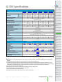
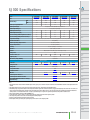
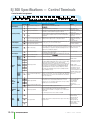
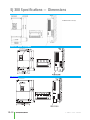
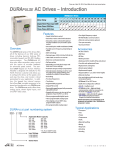
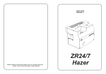
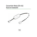
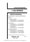
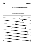
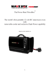
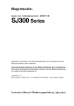
Hitachi SJ300 Series Introduction
SJ300 Series Drives
Motor Rating
The Hitachi SJ300
Series drives are
robust and particularly suited for
constant
torque
and high-starting
torque
applications. The SJ300
offers many features and options that
make this series suitable for a wide range
of applications.
Features
kW
Hp
Three-phase 230V
Three-phase 460V
.4 .75 1.5 2.2 3.7 5.5 7.5 11
.5 1
2
3
5 7.5 10 15
15 18.5 22
20 25 30
✔
✔
✔
✔
✔
remote digital keypad with serial communications (SC-OPE3I), or the optional
Windows-based programming software
DOP-PRO, available for free downlaod
at
www.drivemanager.com.
The
DOP-PRO-CBL programming cable is
required to download configurations to
the drive.
Control and monitoring
• V/F control
• Sensorless vector control
• Flux vector control
• Internal dynamic braking circuit (15 hp)
• PID control
• P/PI control tuning for load sharing applications
• 16 programmable speed levels
• Two-stage accel/decel selection
• Feed-back option board allows for closed
loop vector control and electronic gearing
• Power phase loss detection
• Automatic fan on/off selection
• Modular construction
There are a variety of choices for controlling and monitoring the SJ300 drive.
Some of the choices are listed below:
Digital keypad — The OPE-SRE digital
keypad comes standard with every SJ300
drive. This keypad display allows you to
program your drive as well as monitor
specific parameters during operation. The
OPE-SRE can be mounted on the SJ300
or mounted remotely with an optional
cable.
Configuration methods
The SJ300 Series drives can be configured
multiple ways. The drive can be configured using the removable keypad that
comes with the drive (OPE-SRE), the
Intelligent terminal system — The built-in
intelligent terminal system allows
you
to
connect
a
sourcing
4-20 mA / 0-10 VDC device, such as a
PLC, to control the frequency and run/stop
functions of the drive.
Remote digital keypad with serial communications — The SC-OPE3I has a 4-line,
20-character back-lit LCD display and
built-in EEPROM program storage. The
Hitachi Model Number Convention
SJ3 00--004 L F U
U: USA (North America)
E: European version
(for Europe, Australia, Singapore, etc.)
Series name
✔
✔
✔
✔
✔
✔
✔
✔
✔
✔
✔
✔
✔
✔
✔
✔
SC-OPE3I gives your drive RS-232/
RS-422/RS-485 connectivity and enables
you to communicate with your drive using
multiple serial protocols. The SC-OPE3I has
complete programming and monitoring functionality. The SC-OPE3I can be mounted
on the SJ300 drive in place of the standard keypad, or it can be remotely
mounted.
Accessories
• AC line reactors
• Braking resistors
• Filters
• Remote operator interface
• Remote digital keypad with serial communications
• Windows configuration software
Option cards
The SJ300 Series drives have two option
card slots located on the interior panel of
the drive. The option slots can be used for
an encoder feedback card.
The detailed descriptions and specifications for the
SJ300 accessories and option cards are available
later in this section. See our Web site for future additions.
Typical applications
• Web handling
• Grinders
• Extruding
• Strip forming
• Conveyors
• Fans/Pumps
• Spindles
F: Operator panel equipped
Input power specification
N: 1 or 3 phase (200V class)
L: 3 phase (200V class)
H: 3 phase (400V class)
Applicable motor rating
002 (0.2 kW) to 075 (7.5 kW)
13–2
Drives/Motors/Motion
1 - 80 0 - 633 - 0405
SJ300 Specifications
PLC
Overview
DL05/06
PLC
200V Class Three-phase Input
Model
SJ300-004LFU
SJ300-007LFU
SJ300-015LFU
SJ300-022LFU
SJ300-037LFU
SJ300-055LFU
Price
<--->
<--->
<--->
<--->
<--->
<--->
Motor Rating1
HP
kW
Rated Capacity (240V) kVA
Rated Input Voltage
Rated Output Voltage 2
Rated Input Current (A)
Rated Output Current (A)
1/2HP
1HP
2HP
3HP
5HP
7.5HP
0.4kW
0.75kW
1.5kW
2.2kW
4.0kW
5.5kW
1.2
2.0
3.1
4.3
6.8
9.9
Corresponds to input voltage
3.8
5.5
8.3
12.0
18.0
26.0
3.0
5.0
7.5
10.5
16.5
24
50%
200%
200%
Field I/O
20%
200%
160%
100%
80%
Software
C-more
HMIs
IP20 (NEMA1)
-10 to 40°C (14-104°F)
Other HMI
-20 to 65°C (-68-149°F)
20 to 90% humidity, (no condensation)
Vibration 7
Location
Coating Color
AC Drives
5.9m/s2 (0.6G), 10 to 55 Hz
Motors
Altitude 1,000 m or less, indoors, (no corrosive gases or dust)
Gray
70W
88W
125W
160W
235W
325W
Steppers/
Servos
3.5 (7.7)
Motor
Controls
255x150x140
Accessories
AC Reactor
Braking Resistor
Braking Unit
RF Capacitive Filter
RF Inductive Filter
EMI Filter
Remote Operator Interface
Remote Operator Interface Cables
DL405
PLC
Performs at start under set frequency at deceleration via an external input (braking force, time and operating frequency)
Protective Structure 4
Ambient Operating Temperature 5
Storage Temperature 6
Humidity
Watt Loss 100% (I) 8
Weight: kg (lb)
Dimensions (HxWxD) (mm)
DL205
PLC
DL305
PLC
Three-phase three-wire 200-240V ±10%, 50/60Hz ±5%
Dynamic Braking (without external resistor) 3
Dynamic Braking (with external resistor) 3
DC Injection Braking
DL105
PLC
HRL005L
HRL010L
HRL030L
HRL020L
HRL050L
HRL075L
Refer to “SJ300 Dynamic Braking Resistor Selection Charts” in the “SJ300 Accessories” section of this chapter
built into drive
Pulse Width Modulation Filter for Analog
Output Metering
Photo
Sensors
Limit
Switches
CFI-L
ZCL-B40
NF-CEH7
Proximity
Sensors
NF-CEH10
NF-CEH20
NF-CEH30
SC-OPE3I
Encoders
Current
Sensors
SC-OPE3BK
Pushbuttons/
Lights
FA-4PWM
Process
Notes:
1: The applicable motor refers to Hitachi standard 3-phase motor (4 pole). To use another motor, the rated motor current must NOT exceed the rated output current of
the inverter.
2: The output voltage decreases as the main power supply voltage decreases. (Except when using the AVR function.)
3: The braking torque at capacitive feedback is the average deceleration torque at the shortest deceleration (stoppage from 50/60 Hz) of the motor itself. It is not the
continuous regenerative braking torque. And the average deceleration torque varies with motor loss. This value decreases when operating beyond 50/60 Hz. Note that
a braking resistor is not included in the inverter. If a large regeneration torque is required, the optional regenerative braking resistor should be used.
4: The protection method conforms to JEM 1030/NEMA (U.S.)
5: To use the inverter at 40°C or higher, it is necessary to reduce the output current and carrier frequency values.
6: The storage temperature refers to the short-term temperature during transport.
7: Conforms to the test method specified in JIS CO911 (1984).
8: Rated output current (In). Based upon output frequency 50 Hz or 60 Hz. Carrier frequency 5kHz.
Relays/
Timers
Comm.
TB’s &
Wiring
Power
Circuit
Protection
Enclosures
Appendix
Part Index
w w w. a u to m at i o n d i re c t . c o m / d r i ves
Drives/Motors/Motion
13–3
SJ300 Specifications
200V Class Three-phase Input
Model
SJ300-075LFU
Price
Motor Rating 1
HP
kW
Rated Capacity (240V) kVA
Rated Input Voltage
Rated Output Voltage 2
Rated Input Current (A)
Rated Output Current (A)
SJ300-110LFU
SJ300-150LFU
SJ300-185LFU
SJ300-220LFU
<--->
<--->
<--->
<--->
<--->
10HP
15HP
20HP
25HP
30HP
7.5kW
11.5kW
15kW
18.5kW
22kW
13.3
19.1
26.6
31.5
39.4
Three-phase three-wire 200-240V ±10%, 50/60Hz ±5%
Corresponds to input voltage
35
51
70
84
105
32
46
64
76
95
Dynamic Braking (without external resistor) 3
20%
10%
10%
10%
10%
Dynamic Braking (with external resistor) 3
DC Injection Braking
80%
70%
110%
90%
110%
Starts at set frequency at deceleration via an external input (braking force, time and operating frequency)
Protective Structure 4
Ambient Operating Temperature 5
Storage Temperature 6
Humidity
IP20 (NEMA 1)
-10 to 40°C (14-104ZX°F)
-20 to 65°C (-68-149°F)
25 to 90% humidity, (no condensation)
Vibration 7
Location
Coating Color
Watt Loss 100% (I) 8
Weight: kg (lb)
Dimensions (HxWxD) (mm)
5.9m/s2 (0.6G), 10 to 55 Hz
Altitude 1,000 m or less, indoors, (no corrosive gases or dust)
Gray
425W
600W
800W
975W
5 (11)
12 (26.4)
260x210x170
390x250x190
1150W
Accessories
AC Reactor
Braking Resistor
Braking Unit
RF Capacitive Filter
RF Inductive Filter
EMI Filter
Remote Operator Interface
Remote Operator Interface Cables
Pulse Width Modulation Filter for Analog Output
Metering
HRL110L
HRL115L
HRL120L
HRL130L
HRL130L
Refer to “SJ300 Dynamic Braking Resistor
Selection Charts” in the accessories section
Refer to “Resistor and Braking Unit Combinations” selection tables
(Braking Unit required)
built into drive
Not available from AutomationDirect; visit www.hitachi.us/inverters
CFI-L
ZCL-B40
NF-CEH40
NF-CEH60
NF-CEH80
NF-CEH100
NF-CEH150
SC-OPE3I
SC-OPE3BK
FA-4PWM
Notes:
1: The applicable motor refers to Hitachi standard 3-phase motor (4 pole). To use another motor, the rated motor current must NOT exceed the rated output current of the
inverter.
2: The output voltage decreases as the main power supply voltage decreases. (Except when using the AVR function.)
3: The braking torque at capacitive feedback is the average deceleration torque at the shortest deceleration (stoppage from 50/60 Hz) of the motor itself. It is not the continuous regenerative braking torque. And the average deceleration torque varies with motor loss. This value decreases when operating beyond 50/60 Hz. Note that a braking
resistor is not included in the inverter. If a large regeneration torque is required, the optional regenerative braking resistor should be used.
4: The protection method conforms to JEM 1030/NEMA (U.S.)
5: To use the inverter at 40°C or higher, it is necessary to reduce the output current and carrier frequency values.
6: The storage temperature refers to the short-term temperature during transport.
7: Conforms to the test method specified in JIS CO911 (1984).
8: Rated output current (In) based upon output frequency 50 Hz or 60 Hz. Carrier frequency 5kHz.
13–4
Drives/Motors/Motion
1 - 80 0 - 633 - 0405
SJ300 Specifications
PLC
Overview
400V Class Three-phase Input
Model
Price
Motor Rating 1
HP
kW
Rated Capacity (480V) kVA
Rated Input Voltage
SJ300-007HFU
SJ300-015HFU
SJ300-022HFU
SJ300-040HFU
SJ300-055HFU
<--->
<--->
<--->
<--->
<--->
1HP
2HP
3HP
5HP
7.5HP
.75kW
1.5kW
2.2kW
3.7kW
5.5kW
2.1
3.1
4.4
7.1
9.9
Three-phase three-wire 380-480V ±10%, 50/60Hz ±5%
2.8
4.2
5.8
9.5
13
2.5
3.8
5.3
8.6
12
Dynamic Braking (without optional resistor) 3
50%
50%
20%
20%
20%
Dynamic Braking (with optional resistor) 3
200
200
200
140%
100%
Corresponds to input voltage
Starts at set frequency at deceleration via an external input (braking force, time and operating frequency)
Protective Structure 4
Ambient Operating Temperature 5
Storage Temperature 6
Humidity
IP20 (NEMA 1)
DL405
PLC
Field I/O
Software
-10 to 40°C (14-104°F)
C-more
HMIs
-20 to 65°C (-68-149°F)
Other HMI
AC Drives
5.9m/s2 (0.6G), 10 to 55 Hz
Altitude 1,000 m or less, indoors, (no corrosive gases or dust)
Motors
Gray
88W
125W
160W
235W
325W
Steppers/
Servos
3.5 (7.7)
Motor
Controls
255x150x140
Accessories
AC Reactor
Braking Resistor
Braking Unit
RF Capacitive Filter
RF Inductive Filter
EMI Filter
Remote Operator Interface
Remote Operator Interface Cables
Pulse Width Modulation Filter for Analog
Output Metering
DL205
PLC
25 to 90% humidity, (no condensation)
Vibration 7
Location
Coating Color
Watt Loss 100% (I) 8
Weight: kg (lb)
Dimensions (mm) (HxWxD)
DL105
PLC
DL305
PLC
Rated Output Voltage 2
Rated Input Current (A)
Rated Output Current (A)
DC Injection Braking
DL05/06
PLC
HRL010H
HRL030H
HRL030H
HRL050H
HRL075H
Refer to “SJ300 Dynamic Braking Resistor Selection Charts” in the “SJ300 Accessories” section of this chapter
built into drive
CFI-H
Photo
Sensors
Limit
Switches
ZCL-B40
NF-CEH7
Proximity
Sensors
NF-CEH10
NF-CEH20
SC-OPE3I
Encoders
Current
Sensors
SC-OPE3BK
Pushbuttons/
Lights
FA-4PWM
Notes:
1: The applicable motor refers to Hitachi standard 3-phase motor (4 pole). To use another motor, the rated motor current must NOT exceed the rated output current of the
inverter.
2: The output voltage decreases as the main power supply voltage decreases. (Except when using the AVR function.)
3: The braking torque at capacitive feedback is the average deceleration torque at the shortest deceleration (stoppage from 50/60 Hz) of the motor itself. It is not the continuous regenerative braking torque. And the average deceleration torque varies with motor loss. This value decreases when operating beyond 50/60 Hz. Note that a
braking resistor is not included in the inverter. If a large regeneration torque is required, the optional regenerative braking resistor should be used.
4: The protection method conforms to JEM 1030/NEMA (U.S.)
5: To use the inverter at 40°C or higher, it is necessary to reduce the output current and carrier frequency values.
6: The storage temperature refers to the short-term temperature during transport.
7: Conforms to the test method specified in JIS CO911 (1984).
8: Rated output current (In). Based upon output frequency 50 Hz or 60 Hz. Carrier frequency 5kHz.
Process
Relays/
Timers
Comm.
TB’s &
Wiring
Power
Circuit
Protection
Enclosures
Appendix
Part Index
w w w. a u to m at i o n d i re c t . c o m / d r i ves
Drives/Motors/Motion
13–5
SJ300 Specifications
400V Class Three-phase Input
Model
SJ300-075HFU
Price
Motor Rating 1
HP
kW
Rated Capacity (480V) kVA
Rated Input Voltage
Rated Output Voltage 2
Rated Input Current (A)
Rated Output Current (A)
SJ300-110HFU
SJ300-150HFU
SJ300-185HFU
SJ300-220HFU
<--->
<--->
<--->
<--->
<--->
10HP
15HP
20HP
25HP
30HP
7.5kW
11kW
15kW
18.5kW
22kW
13.3
19.1
26.6
31.5
39.9
Three-phase three-wire 380-480V ±10%, 50/60Hz ±5%
Corresponds to input voltage
18
25
35
42
53
16
23
32
38
48
Dynamic Braking (without optional resistor) 3
20%
10%
10%
10%
10%
Dynamic Braking (with optional resistor) 3
100
70%
200%
200%
200%
DC Injection Braking
Starts at set frequency at deceleration via an external input (braking force, time and operating frequency)
Protective Structure 4
Ambient Operating Temperature 5
Storage Temperature 6
Humidity
IP20 (NEMA 1)
-10 to 40°C (14-104°F)
-20 to 65°C (-68-149°F)
25 to 90% humidity, (no condensation)
Vibration 7
Location
Coating Color
Watt Loss 100% (I) 8
Weight: kg (lb)
Dimensions (mm) (HxWxD)
5.9m/s2 (0.6G), 10 to 55 Hz
Altitude 1,000 m or less, indoors, (no corrosive gases or dust)
Gray
425W
600W
800W
975W
5 (11)
12 (26.4)
260x210x170
390x250x190
1150W
Accessories
AC Reactor
Braking Resistor
Braking Unit
RF Capacitive Filter
RF Inductive Filter
EMI Filter
Remote Operator Interface
Remote Operator Interface Cables
Pulse Width Modulation Filter for Analog Output
Metering
HRL110H
HRL115H
HRL120H
HRL130LH
HRL130H
Refer to “SJ300 Dynamic Braking Resistor
Selection Charts” in the accessories section
Refer to “Resistor and Braking Unit Combinations” selection tables
(Braking Unit required)
built into drive
Not available from AutomationDirect; visit www.hitachi.us/inverters
CFI-H
ZCL-A
NF-CEH20
NF-CEH30
NF-CEH40
NF-CEH50
NF-CEH60
SC-OPE3I
SC-OPE3BK
FA-4PWM
Notes:
1: The applicable motor refers to Hitachi standard 3-phase motor (4 pole). To use another motor, the rated motor current must NOT exceed the rated output current of the
inverter.
2: The output voltage decreases as the main power supply voltage decreases. (Except when using the AVR function.)
3: The braking torque at capacitive feedback is the average deceleration torque at the shortest deceleration (stoppage from 50/60 Hz) of the motor itself. It is not the continuous regenerative braking torque. And the average deceleration torque varies with motor loss. This value decreases when operating beyond 50/60 Hz. Note that a braking
resistor is not included in the inverter. If a large regeneration torque is required, the optional regenerative braking resistor should be used.
4: The protection method conforms to JEM 1030/NEMA (U.S.)
5: To use the inverter at 40°C or higher, it is necessary to reduce the output current and carrier frequency values.
6: The storage temperature refers to the short-term temperature during transport.
7: Conforms to the test method specified in JIS CO911 (1984).
8: Rated output current (In). Based upon output frequency 50 Hz or 60 Hz. Carrier frequency 5kHz.
13–6
Drives/Motors/Motion
1 - 80 0 - 633 - 0405
SJ300 Specifications — General
PLC
Overview
SJ300 Drives Specifications
DL05/06
PLC
Control Method
Sine-wave pulse width modulation (PWM) control
Voltage/Frequency Characteristics
V/F free setting (30-400Hz of base frequency), constant torque and reduced torque of V/F control, sensorless vector control
Speed Fluctuation
Overload Current Rating
Acceleration/Deceleration Time
±0.5% (sensorless vector control)
Starting Torque
200% at 0.5Hz (sensorless vector control), 150% at 0Hz (sensorless vector control with a motor one size frame down
Output Frequency Range 1
0.1 to 400 Hz
Frequency Accuracy
Digital command: ±0.01% of the max. frequency. Analog command:±0.2% of the max frequency (25°C ± 10°C)
Frequency Setting Resolution
Digital: 0.1 Hz, analog: max. frequency/4000 (O terminal: 12bit 0 to 10V, O2 terminal: 12bit -10 to 10V)
150% for 60 seconds, 200% for 0.5 seconds
DL205
PLC
0.1-3000 sec. (linear/curve, acceleration/deceleration selection), two-stage acceleration/deceleration
Forward/Reverse
Start/Stop
Digital Operator Panel
Up and Down keys & value setting and potentiometer
External Signal
0 to 10VDC (input impedance 10k)
-10V to 10V (input impedance 10k), 4-20mA (input impedance 100),
External Port
Digital Operator Panel
Set by external device
External Signal
External Port
Intelligent Input Terminal
Thermistor Input
Intelligent Monitor Output Terminals
Display Monitor
Other Functions
Carrier Frequency Range
Protective Functions
DL405
PLC
Software
C-more
HMIs
Run key/Stop key (Forward/reverse run change by function command)
Forward run/stop (NO contact), Reverse operation command available at terminal assignment
(NO/NC selectable), 3-wire input connection
set by external device
Other HMI
AC Drives
Selection of 8 functions from:
RV(Reverse), CF1-CF4(Multispeed command), JG(Jogging), DB(External DC braking),
SET(Second motor constants setting), 2CH(Second accel./decel.), FRS(Free-run stop), EXT(External trip), USP(Unattended start
protection), CS(Change to/from commercial power supply), SFT(Software lock), AT(Analog input selection), SET3(Third motor
constants setting), RS(Reset), STA(3-wire start),
STP(3-wire stop), F/R(3-wire fwd./rev.), PID(PID On/Off), PIDC(PID reset), CAS(Control gain setting), UP/DWN(Remote-controlled accel./decel.) UDC(Remote-controlled data clearing),
OPE(Operator control), SF1-SF7(Multispeed bit command 1-7), OLR(Overload limit change),
TL(Torque limit enable), TRQ1,TRQ2(Torque limit selection (1)(2)), PPI(P/PI selection),
BOK(Brake verification), ORT(Orientation), LAC(LAD cancel), PCLR(Positioning deviation reset), STAT(90-degree phase difference permission), NO(Not selected)
One terminal (PTC characteristics)
Motors
Steppers/
Servos
Motor
Controls
Proximity
Sensors
Photo
Sensors
Control Output Signal
Intelligent Output Terminals
DL305
PLC
Field I/O
Control Input Signal
Frequency Setting
DL105
PLC
Five open collector terminals and one NO-NC combined contact. Selection from:
RUN(Run signal), FA1(frequency arrival signal (at the set frequency)), FA2(Frequency arrival signal (at or above the set frequency)), OL(Over-load advance notice signal), OD(Output deviation for PID control), AL(Alarm signal), FA3(Frequency arrival signal
(only at the set frequency)),OTQ(Over-torque), IP(Instantaneous power failure signal), UV(Under-voltage signal), TRQ(In torque
limit), RNT(Operation time over), ONT(Plug-in time over), THM(Thermal alarm), BRK(Brake release), BER(Brake error), ZS(Zero
speed), Frequency arrival signal (at or above the set frequency)(2)), Frequency arrival signal (only at the set frequency)(2),
OL2(Overload advance notice signal(2)),(Terminal 11-13 or 11-14 are automatically configured as AC0-AC2 or AC0-AC3
when alarm code output is selected at C62.)
Analog voltage, analog current, pulse line output
Output frequency, output current, motor torque, scaled value of output frequency, trip history, I/O terminal condition, input power,
output voltage
V/f free-setting (up to 5 points), frequency upper/lower limit, frequency jump, accel./decel. curve selection, manual torque boost
value and frequency adjustment, analog meter tuning, start frequency setting, carrier frequency setting, electronic thermal freesetting, external frequency output zero/span reference, external frequency input bias start/end, analog input selection, retry after
trip, restart after instantaneous power failure, various signal outputs, reduced voltage start, overload restriction, default value setting, deceleration and stop after power failure, AVR function, fuzzy accel./decel., auto-tuning (on-line/off-line), high-torque multioperation
0.5-15kHz
Over-current protection, overload protection, braking resistor overload protection, over-voltage protection, EEPROM error, undervoltage error, CT (Current transformer) error, CPU error, external trip, USP error, ground fault, input over-voltage protection,
instantaneous power failure, option 1 connection error, option 2 connection error, inverter thermal trip, phase failure detection,
IGBT error, thermistor error
Note: To operate the motor above 60 Hz, refer to the motor manufacturer’s specification of maximum rotation speed.
Limit
Switches
Encoders
Current
Sensors
Pushbuttons/
Lights
Process
Relays/
Timers
Comm.
TB’s &
Wiring
Power
Circuit
Protection
Enclosures
Appendix
Part Index
w w w. a u to m at i o n d i re c t . c o m / d r i ves
Drives/Motors/Motion
13–7
SJ300 Specifications — Installation
It is important to understand the installation requirements for your SJ300 drive.
This will help to insure that the SJ300
series drives operate within their environmental and electrical limits.
Never use only this catalog for installation or operation of equipment; refer to the user manual.
Environmental Specifications
Protective Structure 1 IP20 (NEMA 1)
Ambient Operating -10 to 40°C (14-104°F)
Temperature 2
Storage
-20 to 65°C (-68-149°F)
Temperature 3
Humidity
20 to 90% RH
(no condensation)
Vibration 4
5.9 m/S2 (0.6G),
10 to 55 Hz
Altitude 1,000 m or less,
indoors (no corrosive
gases or dust)
Location
Coating Color
Temperature probe
4
100
Power source
Gray
Bus Bar
1: The protection method conforms to JEM 1030/
NEMA (U.S.)
2: To use the inverter at 40°C or higher, it is
necessary to reduce the output current and carrier
frequency values.
3: The storage temperature refers to the
short-term temperature during transport.
4
100
4: Conforms to the test method specified in JIS CO911
(1984)
Installation Notes
Panel
Ground braid
copper lugs
Panel ground
terminal
OK
Earth
ground
Watt-loss Chart
Star Washers
Airflow
Panel or Single
Point Ground
SJ300 Drive Model
004LFU/HFU
007LFU/HFU
015LFU/HFU
022LFU/HFU
037LFU/040HFU
055LFU/HFU
075LFU/HFU
110LFU/HFU
150LFU/HFU
185LFU/HFU
220LFU/HFU
300LFU/HFU
370LFU/HFU
450LFU/HFU
550LFU/HFU
100% I*
70W
88W
125W
160W
235W
325W
425W
600W
800W
975W
1150W
1550W
1900W
2300W
2800W
*Rated output current
Based on output frequency 50 Hz or 60 Hz
Carrier frequency 5kHz
13–8
Drives/Motors/Motion
1 - 80 0 - 633 - 0405
SJ300 Specifications — Terminals
PLC
Overview
Main Circuit Terminals
DL05/06
PLC
Symbol
Description
R(L1), S(L2), T(L3)
P(+), N(-)
Main power supply input
terminals
Inverter output terminals
DC link choke
connection terminals
External braking resistor
connection terminals
External braking unit
connection terminals
G or
Ground terminal
R0(R0), T0(T0)
Control power supply input terminals
U(T1), V(T2), W(T3)
PD(+1), P(+)
P(+), RB(RB)
DL105
PLC
DL205
PLC
DL305
PLC
DL405
PLC
RJ45 port
Option card slots
Control circuit terminals
Field I/O
Terminal arrangement
Software
004LFU, 007-055LFU/HFU
075-110LFU/HFU
R
S
T
U
V
W
R
S
T
U
V
W
L1
L2
L3
T1
T2
T3
L1
L2
L3
T1
T2
T3
PD
P
N
RB
G
G
+1
+
-
RB
G
G
R0
T0
PD
P
N
RB
R0
T0
+1
+
-
RB
R0
T0
R0
T0
Other HMI
220LFU
150-185LFU, 150-220HFU
G
C-more
HMIs
R0
T0
R0
T0
R0
T0
R0
T0
R
S
T
PD
P
N
U
V
W
L1
L2
L3
+1
+
-
T1
T2
T3
G
AC Drives
R
S
T
PD
P
N
U
V
W
L1
L2
L3
+1
+
-
T1
T2
T3
Motors
Steppers/
Servos
SJ300-004LFU
G
G
Motor
Controls
Standard Wiring
Inverter Model
SJ300004LFU
007LFU
015LFU
022LFU
037LFU
055LFU
075LFU
110LFU
150LFU
185LFU
220LFU
007HFU
015HFU
022HFU
040HFU
055HFU
075HFU
110HFU
150HFU
185HFU
220HFU
Motor Output
kW (Hp)
Wiring
Power Wires
Signal Lines
0.4 (0.5)
AWG 16
5A
0.75 (1)
AWG 16
10A
1.5 (2)
AWG 14
15A
2.2 (3)
AWG 14
20A
3.7 (5)
AWG 10
30A
5.5 (7.5)
AWG 8
40A
7.5 (10)
AWG 6
60A
11 (15)
AWG 4
80A
15 (20)
AWG 2
100A
18.5 (25)
AWG 1
22 (30)
AWG 1/0
0.75 (1)
AWG 16
1.5 (2)
AWG 16
2.2 (3)
AWG 16
0.75mm
shielded wire
18AWG
2
Proximity
Sensors
Fuse
(Class J)
Photo
Sensors
Limit
Switches
Encoders
Current
Sensors
Pushbuttons/
Lights
120A
Process
150A
6A
10A
Relays/
Timers
Comm.
3.7 (5)
AWG 14
15A
5.5 (7.5)
AWG 12
20A
7.5 (10)
AWG 10
30A
11 (15)
AWG 8
40A
15 (20)
AWG 6
50A
18.5 (25)
AWG 6
60A
22 (30)
AWG 4
80A
TB’s &
Wiring
Power
Circuit
Protection
Enclosures
Appendix
Part Index
w w w. a u to m at i o n d i re c t . c o m / d r i ves
Drives/Motors/Motion
13–9
SJ300 Specifications — Control Terminals
Control terminal arrangement
Control Terminal Specifications
Symbol Name
Power Supply
L
H
Digital monitor (Voltage)
P24
Power terminal for interface
Maximum frequency is attained at DC 10V in DC 0-10V range. Set the voltage at A014 to command maximum frequency below DC 10V.
Power Supply
Contact
Input
Open
Collector
Output
CM1
Common terminal for interface
Run
Command
FW
Forward command input
Functions
1
2
3
4
5
6
7
8
Common
Terminal
PLC
State
11
12
13
14
15
CM2
Thermistor Sensor
Input
TH
Intelligent input terminals
Common terminal for intelligent input
terminals
Intelligent output terminals
Common terminal for intelligent output
terminals
State/
Alarm
AL1
Internal power supply for input terminals. In case of source type logic, comDC 24V, 100mA max.
mon terminal for contact input terminals.
Common terminal for P24, TH, and FM. In case of sink type logic, common termi—
nal for contact input terminals. Do not ground.
Forward command input
Input ON condition
Selection of 8 functions from: RV(Reverse), CF1-CF4(Multispeed command),
Voltage between each termiJG(Jogging), DB(External DC braking), SET(Second motor constants setting),
nal and PLC: DC 18V min.
2CH(Second accel./decel.), FRS(Free-run stop), EXT(External trip),
USP(Unattended start protection), CS(Change to/from commercial power supply), SFT(Software lock), AT(Analog input selection), RS(Reset), STA(3-wire Input OFF condition
start), STP(3-wire stop), F/R(3-wire fwd./rev.), PID(PID On/Off), PIDC(PID
Voltage between each termireset), UP/DWN(Remote-controlled accel./decel.) UDC(Remote-controlled
nal and PLC: DC 3V max.
data clearing), SF1-SF7(Multispeed bit command 1-7), OLR(Overload limit
Input impedance between
change), and NO(Not selected)
each terminal and PLC: 4.7
Allowable maximum voltage
Select sink or source logic with the short-circuit bar on the control terminals.
between each terminal and
Sink logic: Short P24 to PLC / Source logic: Short CM1 to PLC. When apply- PLC: DC 27V
ing external power source, remove the short-circuit bar and connect PLC terminal to the external device.
Decrease in voltage between
Select 5 functions of inverter state and configure them at terminal 11-15.
each terminal and CM2:
When the alarm code is selected at C062, terminal 11-13 or 11-14 are
4V max. during ON
reserved for error codes of inverter trip. Both sink and source logic is always
Allowable maximum
applicable between each terminal and CM1.
voltage: DC 27V
Allowable maximum current:
Common terminal for intelligent output terminal 11-15.
50mA
Thermistor input terminal
Alarm output terminals
Maximum capacity of relays
AL1-AL0: AC 250V,
2A(R load)/0.2A(I load)
In default setting, an alarm is activated when inverter output is turned off by a AL2-AL0: AC 250V,
protective function.
1A(R load)/0.2A(I load)
Minimum capacity of relays
AL1-AL0: AC100V,
10mA DC5V, 100mA
AL2
13–10
DC0-10V output (PWM output) Selection of one function from: Output frequency, output current, torque, output voltage, input power, electronic thermal Digital output frequency range:
load ratio. Digital pulse output (Pulse voltage DC 0/10V) Outputs the value of 0-3.6kHz, 1.2mA max.
output frequency as digital pulse (duty50%)
The inverter trips when the external thermistor detects abnormal temperature.
Common terminal is CM1 [recommended thermistor characteristics].
Allowable rated power: 100mW or over. Impedance in case of abnormal temperature: 3k
Note: Thermal protection level can be set between 0-9999
AL0
Relay
Output
—
FM
AM
Monitor Output
Ratings
Common terminal for H, O, O2, OI, AM, and AMI.
Do not ground.
Power supply for frequency command input
AMI
O2
OI
Monitor Output
Explanation of Terminals
DC 10V, 20mA max.
Input impedance: 10k,
Frequency command terminal
Allowable input voltage range:
DC -0.3 to +12V
O2 signal is added to the frequency command of O or OI in DC 0-±10V
Input impedance: 10k,
Frequency command extra terminal
range. By changing configuration, frequency command can be inputted also Allowable input voltage range:
(Voltage)
at O2 terminal.
DC 0 to±12V
Input impedance: 100k,
Maximum frequency is attained at DC 20mA in DC 4-20mA range. When the
Frequency command terminal (Current)
Allowable input voltage range:
intelligent terminal configured as AT is on, OI signal is enabled.
DC 0-24mA
Analog output monitor (Voltage)
DC 0-10V, 2mA max
Selection of one function from: output frequency, output current, torque, output voltage, input power, electronic thermal load ratio
DC 4-20mA, 250 max.
Analog output monitor (Current)
O
Frequency Setting
Common terminal for analog power
source
Power source for frequency
Drives/Motors/Motion
—
1 - 80 0 - 633 - 0405
SJ300 Specifications — Dimensions
PLC
Overview
SJ300 -004LFU, 007–055LFU/HFU
DL05/06
PLC
DL105
PLC
2 - Ø 6 (Ø 0.24)
All Dimensions in mm (in)
DL205
PLC
DL305
PLC
3 - Ø 27.5 (Ø 1.08)
DL405
PLC
Field I/O
Software
C-more
HMIs
Other HMI
SJ300 -075 – 110LFU/HFU
AC Drives
Motors
2 - Ø 7 (Ø 0.28)
Steppers/
Servos
4 - Ø 30 (Ø 1.18)
Motor
Controls
Proximity
Sensors
Photo
Sensors
Limit
Switches
Encoders
Current
Sensors
SJ300 -150 – 220LFU/HFU
Pushbuttons/
Lights
Process
Relays/
Timers
Comm.
TB’s &
Wiring
Power
Circuit
Protection
Enclosures
Appendix
Part Index
w w w. a u to m at i o n d i re c t . c o m / d r i ves
Drives/Motors/Motion
13–11
SJ300 Specifications — Dimensions
SJ300 -300LFU/HFU
All Dimensions in mm (in)
SJ300 -370 – 450LFU, SJ370-550HFU
2 - Ø 12 (Ø 0.47)
SJ300-550LFU
2 - Ø 12 (Ø 0.47)
13–12
Drives/Motors/Motion
1 - 80 0 - 633 - 0405