1
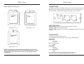
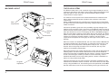
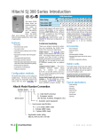
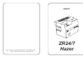
USER GUIDE
VERSION 1.1
Martin Professional A/S,Olof Palmes Allé 18, DK-8200,Aarhus N
Phone: +45 87 40 00 00 Internet: www.martin.dk
ZR24/7
Hazer
ZR24/7 Hazer
ZR24/7 Hazer
CONNECTIONS
Fluids Suitable for this system:
The DMX connections and Status LEDs are mounted on the panel below the
display unit. The following drawing shows the functions and connections.
The 5 pin DMX connections are placed above the 3 pin connectors.
Pro-Haze
Fluid
DJ
Fluid
DMX
1 GND
2 COLD
3 HOT
LED
POWER
FLUID CAL
TEMP CAL
AVR PORT
OUT
IN
LED FUNCTIONS
Temperature = ‘Lo’
Temperature = ‘nor’
Pro-Smoke
Fluid
Temperature = ‘Hi’
NOTE! The warranty on this machine is conditional on the use of
genuine JEM / Martin fluid only. Other fluids may represent a health
hazard when used in this machine, and may damage the internal
components.
Power LED: Shows that the main power supply is operating.
Fluid Cal LED: Not used on this model.
Temp Cal LED: Shows that the system is calibrating the temperature control
system.
FUSE RATINGS
The ZR24/7 Hazer uses three fuses.
They should be replaced with the value and type detailed below:
230V model
Power PCB
F1 6.3AT
F2 3.15AT
Main Fuse (IEC inlet)
6.3AT
115V model
Power PCB
F1 10AT
F2 3.15AT
Main Fuse (IEC inlet)
10AT
Two of these fuses are located internally and should not be
accessed without first disconnecting the power supply.
17
ZR24/7 Hazer
SPECIFICATION
HEAT EXCHANGER
900W
Wide bore steel vaporizing coil
Non resettable over-temperature protection
Electronic Temperature control using thermocouple
ZR24/7 Hazer
USER
GUIDE
USER
GUIDE
USER GUIDE CONTENTS
Introduction
2
Features
2
Safety Guidelines
3
Machine Layout
4
Commissioning The Machine
5
REMOTE CONTROL OPTIONS
DMX512 decoder:
Required Channels = 2
Output is proportional for all levels above 8%
Channels supported = 1 to 509
Valid start codes = 0 (dimmer data only)
Full framing error detection implemented
Digital control via Digital Multifunction Controller.
Digital Machine to Machine link
Remote Control Options
5
DMX Operation
6
Machine to Machine Link
7
The Display
8
The Remote Control
10
CONTROL PANEL
LED display with 4 button keypad
Output level control from 0 to 20
Fan speed control from 0 to 20
Timer range:
Delay time (toF) 0 seconds - 90 seconds
Run time (ton) 0 seconds - 90 seconds
The Timer
11
Basic Operation
12
The Fluid System
13
Display Messages
14
OUTPUT DIRECTION CONTROL
Airflow inclination can be set in the range 0 to 60 degrees.
Basic Fault Finding
15
Specification
16
Connections
17
Fuse Ratings
17
FLUID SYSTEM
Electronic low fluid detection
2.5L fluid container
Maximum fluid consumption 410mL/hour (Haze fluid, HOT = Lo)
POWER REQUIREMENTS (dependant on model)
Input voltage 200 - 250Vac
Input power (max) 975W @ 230V
Main fuse 6.3AT
Input voltage 100 - 130Vac
Input power (max) 975W @ 115V
Main Fuse 10AT
Frequency 50/60Hz both models
16
© 2002 Martin Professional A/S, Denmark.
All rights reserved. No part of this manual may be reproduced, in any form or
by any means, without permission in writing from Martin Professional A/S,
Denmark.
1
ZR24/7 Hazer
ZR24/7 Hazer
USER
GUIDE
USER
GUIDE
INTRODUCTION
BASIC FAULT FINDING
The ZR24/7 Hazer is the first of a new generation of professional Haze
machines, designed for touring and installation in a variety of applications.
Provision has been made for easy integration into most common control
systems currently used in the entertainment industry. As well as providing
remote control options via DMX, the machine comes with a comprehensive
control panel for local operation and display of operating parameters.
The ZR24/7 Hazer is a complex machine and will require a competent
service technician to repair any major faults. However, the following guide
will allow the user to overcome the more common problems.
When replacing fuses, always use one of the correct type and rating (see
specifications in this book).
The effect is provided by a conventional heat exchanger based vaporiser, fed
from a unique liquid atomizer system. This technique is the key to a smooth
and uniform production of effect at the machine’s output duct, along with low
specific fluid consumption. Air is added to the effect, prior to exit, from the
fan mounted in the side of the machine. This increases the volume of the
effect and allows the output to be dispersed over a wide area.
The output angle of the airflow can be adjusted using the thumb-wheels in
the fluid compartment, thus allowing the user to control the vertical
dispersion of the effect.
A container with 2.5L capacity is provided for fluid. To allow reliable
unattended operation, the fluid level is monitored electronically, and the
machine shut down if necessary. No fluid sensor is used, but an indirect
measurement is made based on an energy balance calculation.
FEATURES
2.5L fluid capacity
Electronic low fluid detection
Continuous operation
High pressure piston pump.
All digital control system
LED display for User settings
900W heat exchanger
Fog and Fan controls for easy setup.
DMX512 interface (two channel)
Accurate timer
Non-volatile memory for user
settings and calibration data
2
SYMPTOM
CAUSE
CURE
No haze output when
the machine is in run
mode.
Machine is not ready
Fluid is below min level
Machine faulty
Allow time to reheat
Add fluid
Consult distributor
No haze output when
using DMX to fire the
machine.
Incorrect DMX address
Machine not ready
No DMX termination
Check settings
Allow time with DMX on
Fit 120 ohm resistor
Flu/Out is displayed on
the display
Fluid level is below min Add more fluid, and use
prime menu to restart
machine
Machine is not ready
after 4 minutes.
DMX ch2 is > 245
Blown fuse on Power
control PCB
Haze disperses too
quickly
Wrong grade of fluid
Choose a longer lasting
used for the application fluid (see front cover)
Fan level too high
Reduce fan speed
Increase DMX level
Disconnect supply and
replace fuse.
Digital remote interface.
15
ZR24/7 Hazer
ZR24/7 Hazer
USER
GUIDE
USER
GUIDE
DISPLAY MESSAGES
SAFETY GUIDELINES
The following list shows the messages possible, and the context under which
they are displayed. Only the messages available under normal operation are
shown. Messages shown when using the menus, are detailed in other
sections of this handbook.
Always use JEM / Martin approved fluid in the container supplied with the
machine. Do not attempt to override the fluid sensing system, as this could
cause damage to the machine.
Ht
Displayed when the heater is running but the machine is not
ready.
rdy
The machine is ready to run using the run menu options.
Not displayed when using DMX.
FLu/out
Indicates that the fluid in the container is below the minimum
level to operate the machine. Only visible when the machine
has reached the ready state. Reset using the Pri menu,
after refilling the fluid container.
Fog/08
The run menu is set to ‘on’. The number displayed is the
current Fog output level in the range 0 to 20
Use level 0 to operate the fan without haze output.
Ht/Err
An over-temperature condition has occured on the heat
exchanger. Reset by power off.
CAL/Err
The control software has detected corrupt calibration
settings in the EEprom memory, and has shut the machine
down.
Check that the local supply voltage is correct for use with the machine. The
voltage setting is printed on the serial label.
The machine must be operated in a horizontal position and should not be
suspended overhead.
Observe the warnings displayed on the machine.
Always use smoke machines in well ventilated areas. High smoke density
could affect sufferers of asthma or other severe respiratory disorders.
Smoke machines can cause condensation to form. Floors and surfaces may
become slippery and should be checked regularly.
This machine is not waterproof, and should not be exposed to wet outdoor
conditions.
Do not spill fluid over the machine. If fluid is spilt, disconnect the power
supply and clean with a damp cloth.
Refer servicing to qualified service personnel. Disconnect the machine from
the power supply before removing any covers.
Mains Cable Wiring Instructions
UK/EU cable colours:
Brown = Live
Blue = Neutral
Green / Yellow = Earth
14
The ZR24/7 Hazer is fitted with an
IEC power inlet with integral fuse
draw. A suitable IEC mains cable
should be used to connect to the
supply system.
This equipment must be earthed.
3
ZR24/7 Hazer
ZR24/7 Hazer
USER
GUIDE
MACHINE LAYOUT
USER
GUIDE
THE FLUID SYSTEM
The ZR24/7 Hazer uses a 2.5L container to give approximately 6 hours of
continuous operation at full output. Power supply voltage fluctuations should
have little effect on this, since the unit has automatic supply voltage
compensation for pump speed.
Display unit
Fluid
compartment
DMX in/out
3/5 pin
Remote
input
On/Off switch
Power inlet
with fuse
The machine control system uses a water based fluid to create the haze
effect, and has adequate power to produce the maximum haze output
continuously.
Supply voltage and frequency variations are measured and compensated
for, within the limits of the specified operating voltage/frequency range for the
model concerned.
Continuous operation gives rise to the possibility of pump damage if the
machine runs out of fluid. This is overcome in the ZR24/7 Hazer by using an
indirect electronic fluid sensing system, ensuring that the pump is shut down
when the fluid level is too low. The display will show a Flu Out message to
warn the user that the machine is shut down due to lack of fluid. The indirect
nature of the system means that it is slow to respond, and may take up to 10
minutes to recognize a low fluid condition. However, the fluid system
components are capable of running dry for this length of time, with no risk of
damage.
When the machine is refilled with fluid, the user must reset the Flu Out error
by entering the Pri menu and choosing ‘y’, followed by the enter key. This
will clear the error and prime the fluid system ready for use. The prime
function will run the pump at maximum for 10 seconds, but only if the
machine is at operating temperature.
Remember that the type of fluid used will play a large part in determining the
resulting effect. The list of fluids inside the front cover of this handbook
shows the main fluids compatible with this machine. Choose a fluid suitable
for the venue and type of effect you want to create. Generally, use the
standard Haze fluid, but for longer lasting effects, contact a distributor for
advice on using another fluid grade.
Haze outlet
Air-guide
adjustment
4
Changing the fluid type may also require the operating temperature of the
machine to be altered to suit the new fluid. This can be done from the display
unit by using the Hot menu, and selecting from the options Hi, Lo and Nor.
See the inside front cover for the correct setting for the type of fluid in use.
13
ZR24/7 Hazer
USER
GUIDE
ZR24/7 Hazer
BASIC OPERATION
COMMISSIONING THE MACHINE
The following instructions explain how to operate the basic functions of the
machine. It is assumed that the machine is being started from cold.
Unpack the machine and look for any obvious signs of damage.
Starting with the run menu showing oFF, go through the following sequence.
Allow the machine to reach operating temperature.
Display shows Ht
When the machine is ready (after approx. 2 minutes warm-up time) haze can
be produced.
Display shows rdy
Set the run menu to on
Set the fog menu to 8
Set the fan menu to 15
Check that the Hot menu suits the fluid type
Display shows FOG/08
If starting the machine for the first time, or after the fluid has been changed,
the pump may need to be primed.
Do this by selecting the Pri menu and selecting ‘y’ followed by the enter key.
The pump will run at full output for 10 seconds, but only if the machine is at
operating temperature. Refer to the Fault Finding section of the handbook
for advice if the unit does not prime correctly.
Set the run menu to ON to produce continuous output.
Fog display shows FOG/08
Set the run menu to tr to produce timed output (read the Timer section to
see how to configure the timer).
Fog display shows ton/04,toff/03 etc
The output angle of the airflow can be adjusted using the V.G.A system.
Alterations are made using the two thumb wheels located in the fluid
compartment. Slacken the lower screw by ¾ of a turn, and then the upper,
while sliding the unit up or down as required.
Do not remove either of the screws, since this will require dismantling of the
machine to repair.
Note that setting the FOG level, will override the fan speed setting and run
the fan at the minimum speed allowed for this output level. If a higher fan
speed is required, use the fan menu to set the level. When the fan is in
override, a flashing bar is displayed in front of the speed value.
12
USER
GUIDE
Place the machine on a level surface and fit a container of JEM/Martin
approved fluid into the fluid compartment. Fit the fluid line and cap to the
container.
Check the wiring instructions in the Safety Guidelines section of this
handbook and connect the machine to the power supply.
Set the power switch on the rear panel to the ON position, and look for the
start-up message on the displays (software revision number).
Refer to the Basic Operation section of this handbook for information on how
to use the main functions of the machine. Read the Safety Guidelines before
using the machine.
REMOTE CONTROL OPTIONS
The ZR24/7 Hazer provides the user with 3 ways to implement a remote
control on the machine. The main control panel is fixed and can not be
removed for remote operation. The DMX interface is located on the panel
adjacent to the control panel and the remote interface sits alongside the
mains switch.
The options are:
DMX 512 Digital Interface
The interface uses the two XLR 3/5 connectors marked DMX on the
interface panel, and uses the usual DMX electrical standards (RS 485). The
inputs are protected against overvoltage and an ouput connector is provided
to allow multidrop operation of the link.
Remote Interface
The remote interface uses a male XLR 3 connector to allow an optional
digital remote to control the machine.
Full control of the output and timers can be achieved, at distances of up to
25m.
Machine to machine link
By using one machine as a master, and linking the DMX out to other
machines, a digital slave system can be created. This allows all machines to
be slaved to the operation of the first machine in the link. Only use cables
that meet the DMX specification. The master machine may be controlled
using a remote if required.
5
ZR24/7 Hazer
ZR24/7 Hazer
USER
GUIDE
USER
GUIDE
DMX OPERATION
THE TIMER
The machine may be operated using the industry standard DMX 512 digital
control protocol. This allows the control of the fog system to be easily
integrated with the lighting system in most installations.
DMX may be used without changing any of the settings on the main control
panel. When the system detects a valid DMX data stream on the input, the
control will default to the DMX system levels. Any attempts to control the
machine from the control panel will have no effect until the DMX signal is
removed. The display will show the current DMX base address.
The timer system is implemented in software using the machine’s main
control PCB. As such, the timing is crystal controlled and will be of good
accuracy when compared to the usual analogue timers commonly found on
fog machines. The timer is enabled by setting the run menu to ‘tr’.
Selecting this option will cause the timer to start from the beginning of the
ON period and run through to the end of the OFF period, the cycle will then
repeat until the run menu is set to OFF. The timer will only function when the
run menu is set to ‘tr’ and the machine is ready (RdY). Switching the run
menu to OFF at any time during the cycle will halt the operation.
The machine requires two channels, with the address of the first channel set
using the Adr menu. The channels control the Fog and Fan settings in the
following manner.
While the timer is running, the display will show the elapsed time in seconds.
The display will alternate between the period name (ton/toF) and the elapsed
time in seconds.
Channel 1
Fog output level
0 - 19 zero output (dead-band)
20 - 220 proportional output level control
Implemented in 20 discrete steps
220 - 230 Prime function
To set the time periods, use the Menu key on the display to set the ton menu
as current. Press the Enter key to see the current value for the On Time
(ton), and make adjustments using the Up/Down keys. Now press enter to
store the value and use the menu key to select the Off Time (toF) menu.
Adjust the value as for the On Time, and then set the run menu to ‘tr’ to test
the settings.
Channel 2
Fan speed setting
0 - 19 Fan off
20 - 220 proportional speed control
Implemented in 20 discrete steps
220 - 230 Auto fan mode
245 - 255 Fan off, Fog off, Heater off
The current Fog and Fan levels will be used by the timer system when in the
ON period.
The system implements true proportional control of the fog output rather than
the simple switching functions found on some other equipment.
The DMX base address can be set to any channel in the range 1 - 509 using
the Adr menu.
The onboard timer functions are not accessable via the DMX system. Any
timing of the output must be done using the programming capabilities of the
DMX console being used to control the system.
5 pin DMX connections, are provided as standard, along with the lower cost
3 pin types, thus allowing for all types of installation.
6
11
ZR24/7 Hazer
USER
GUIDE
ZR24/7 Hazer
USER
GUIDE
THE REMOTE CONTROL
MACHINE TO MACHINE LINK
The ZR24/7 Hazer is not supplied with a remote control as standard. This is
a reflection of the increasing popularity of DMX control, which can be used
directly with the ZR24/7 Hazer.
However, there is always a situation where DMX is not available or
appropriate, and the digital remote control available for the ZR24/7 Hazer
provides a solution.
This feature is designed for users who do not have DMX equipment, but who
need to link multiple machines and control them from a single source.
The Universal Digital Remote allows access to all the key control parameters
via the digital interface connector mounted on the rear of the machine. The
unit uses a high brightness LED display, and will allow the adjustment of all
parameters supported by this machine.
The remote is supplied with a 5m link cable, but can be used with cables up
to 25m long.
The pin allocations on the remote connector are as follows:
Pin
1
2
3
Function
Ground
+15V
Data (0 - 5V)
By linking the machines using the DMX sockets in a multi-drop cable
arrangement, a single master machine can be used to operate a maximum
of 16 machines. Since the data transmission is done over DMX compatible
media, the distances of the cable runs need only comply with the normal
limitations of a DMX system. Equally, DMX system components (isolators
etc.) can be used if required. To avoid driver contention, the link system
should never be connected to a live DMX installation.
To use the system, one machine must be selected as the master, and the
Lnk menu set to tr (transmit). This machine will transmit the current settings
to the other machines in the link, and may use a remote control. All
machines other than the master will have Lnk set to rc for receive only.
All machines are now ‘slaved’ to the master machine and perform the same
actions; no individual control is possible.
All slave machines should have their DMX base address set to 1. The
address of the master machine is not important. No status information for
any of the slave machines will be available at the master, only that of the
master machine itself.
Note that the remote allows access to the Auto Fan mode and the Prime
function via the Alt menu. The functions of the menu are as follows:
Alt:
0 All Alt Menu functions are disabled.
1 Auto Fan Mode, in which the fan will cycle between 50% and 100%
over a 2 minute (approx) cycle time.
2 An alternative way to engage the Prime Mode.
3 This option is currently not allocated, but may support new features
on future versions of the machine.
10
7
ZR24/7 Hazer
USER
GUIDE
ZR24/7 Hazer
USER
GUIDE
THE DISPLAY
An LED display is used in the ZR24/7 Hazer to show status and control
information.
Located below the display are 4 function keys that can be used to control the
display and the settings on the machine. The functions of the keys are
shown in the following drawing.
To store the new value into non-volatile memory, the enter key must be
pressed before moving on to another menu or leaving the edit mode. The
display will show SEt when the operation is complete.
When not in edit mode, the display will show information appropriate to the
current operating mode. To do this, the display will alternate between two
messages. The duration of the first message is typically 1 second, whilst the
second message will be visible for 2 seconds. Some messages are
compounded together to form one message, eg FLu/out indicating low fluid
in the fluid container.
As an example, when the run menu is set to on with an ouput level of 08,
the display will alternate between Fog and 08. For more information about
the messages to expect, see the sections covering the different control
functions on the machine, eg ‘THE TIMER’. The section entitled ‘DISPLAY
MESSAGES’ contains a complete list of the messages and the
circumstances under which they are displayed.
The menus available and the functions they perform are as follows:
MENU
KEY
ENTER UP KEY
KEY
DOWN
KEY
The message displayed will depend on the operating mode of the machine at
the time. However, pressing the menu key at any time will cause the display
to go into the edit mode, allowing the operating parameters to be adjusted.
After approximately 25 seconds since the last keystroke, the display will
leave the edit mode and revert to displaying the current status information.
Pressing the menu key will display the current menu function, whilst pressing
and holding will scroll through the available menus. All keys work the same
way, and can be operated with single keystrokes or held down to force the
display to scroll through the available options/values. The scrolling function
comes into operation 1 second after the key is pressed.
When the user has set the required menu function, pressing the enter key
will display the current value associated with that menu item. The user can
now use the UP/DOWN keys to move through the available options/values
either by single keystrokes or by scrolling.
8
Fog: Sets the current Fog output level in the range 0 to 20.
Fan: Sets the output Fan level (0-20).
Ton: Sets the ON time of the Timer in the range 0 to 90 (seconds).
ToF: Sets the OFF time of the Timer in the range 0 to 90 (seconds).
Run: Allows local operation without the remote.
Adr: Sets the base address for DMX operation.
Hot: Allows the user to adjust the operating temperature.
Lnc: Sets the operating mode of the DMX input.
Alt:
0 All Alt Menu functions are disabled.
1 Auto Fan Mode, in which the fan will cycle between 50% and 100%
over a 2 minute (approx) cycle time.
2 An alternative way to engage the Prime Mode without using the
Prime Menu. This allows the prime function to be used from the remote
control.
3 This option is currently not allocated, but may support new features
on future versions of the machine.
Rst: Allows the user to return all menu items to default values.
Pri: Starts the 10 second priming cycle.
9