1
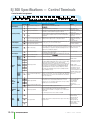
SJ300 Specifications — Control Terminals
Control terminal arrangement
Control Terminal Specifications
Symbol Name
Power Supply
L
H
Digital monitor (Voltage)
P24
Power terminal for interface
Maximum frequency is attained at DC 10V in DC 0-10V range. Set the voltage at A014 to command maximum frequency below DC 10V.
Power Supply
Contact
Input
Open
Collector
Output
CM1
Common terminal for interface
Run
Command
FW
Forward command input
Functions
1
2
3
4
5
6
7
8
Common
Terminal
PLC
State
11
12
13
14
15
CM2
Thermistor Sensor
Input
TH
Intelligent input terminals
Common terminal for intelligent input
terminals
Intelligent output terminals
Common terminal for intelligent output
terminals
State/
Alarm
AL1
Internal power supply for input terminals. In case of source type logic, comDC 24V, 100mA max.
mon terminal for contact input terminals.
Common terminal for P24, TH, and FM. In case of sink type logic, common termi—
nal for contact input terminals. Do not ground.
Forward command input
Input ON condition
Selection of 8 functions from: RV(Reverse), CF1-CF4(Multispeed command),
Voltage between each termiJG(Jogging), DB(External DC braking), SET(Second motor constants setting),
nal and PLC: DC 18V min.
2CH(Second accel./decel.), FRS(Free-run stop), EXT(External trip),
USP(Unattended start protection), CS(Change to/from commercial power supply), SFT(Software lock), AT(Analog input selection), RS(Reset), STA(3-wire Input OFF condition
start), STP(3-wire stop), F/R(3-wire fwd./rev.), PID(PID On/Off), PIDC(PID
Voltage between each termireset), UP/DWN(Remote-controlled accel./decel.) UDC(Remote-controlled
nal and PLC: DC 3V max.
data clearing), SF1-SF7(Multispeed bit command 1-7), OLR(Overload limit
Input impedance between
change), and NO(Not selected)
each terminal and PLC: 4.7
Allowable maximum voltage
Select sink or source logic with the short-circuit bar on the control terminals.
between each terminal and
Sink logic: Short P24 to PLC / Source logic: Short CM1 to PLC. When apply- PLC: DC 27V
ing external power source, remove the short-circuit bar and connect PLC terminal to the external device.
Decrease in voltage between
Select 5 functions of inverter state and configure them at terminal 11-15.
each terminal and CM2:
When the alarm code is selected at C062, terminal 11-13 or 11-14 are
4V max. during ON
reserved for error codes of inverter trip. Both sink and source logic is always
Allowable maximum
applicable between each terminal and CM1.
voltage: DC 27V
Allowable maximum current:
Common terminal for intelligent output terminal 11-15.
50mA
Thermistor input terminal
Alarm output terminals
Maximum capacity of relays
AL1-AL0: AC 250V,
2A(R load)/0.2A(I load)
In default setting, an alarm is activated when inverter output is turned off by a AL2-AL0: AC 250V,
protective function.
1A(R load)/0.2A(I load)
Minimum capacity of relays
AL1-AL0: AC100V,
10mA DC5V, 100mA
AL2
13–10
DC0-10V output (PWM output) Selection of one function from: Output frequency, output current, torque, output voltage, input power, electronic thermal Digital output frequency range:
load ratio. Digital pulse output (Pulse voltage DC 0/10V) Outputs the value of 0-3.6kHz, 1.2mA max.
output frequency as digital pulse (duty50%)
The inverter trips when the external thermistor detects abnormal temperature.
Common terminal is CM1 [recommended thermistor characteristics].
Allowable rated power: 100mW or over. Impedance in case of abnormal temperature: 3k
Note: Thermal protection level can be set between 0-9999
AL0
Relay
Output
—
FM
AM
Monitor Output
Ratings
Common terminal for H, O, O2, OI, AM, and AMI.
Do not ground.
Power supply for frequency command input
AMI
O2
OI
Monitor Output
Explanation of Terminals
DC 10V, 20mA max.
Input impedance: 10k,
Frequency command terminal
Allowable input voltage range:
DC -0.3 to +12V
O2 signal is added to the frequency command of O or OI in DC 0-±10V
Input impedance: 10k,
Frequency command extra terminal
range. By changing configuration, frequency command can be inputted also Allowable input voltage range:
(Voltage)
at O2 terminal.
DC 0 to±12V
Input impedance: 100k,
Maximum frequency is attained at DC 20mA in DC 4-20mA range. When the
Frequency command terminal (Current)
Allowable input voltage range:
intelligent terminal configured as AT is on, OI signal is enabled.
DC 0-24mA
Analog output monitor (Voltage)
DC 0-10V, 2mA max
Selection of one function from: output frequency, output current, torque, output voltage, input power, electronic thermal load ratio
DC 4-20mA, 250 max.
Analog output monitor (Current)
O
Frequency Setting
Common terminal for analog power
source
Power source for frequency
Drives/Motors/Motion
—
1 - 80 0 - 633 - 0405