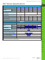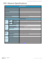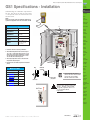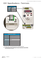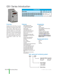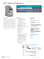
1
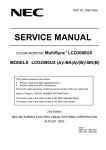
Prices as of April 16, 2014. Check Web site for most current prices.
GS1 Series Introduction
GS1 Series Drives
Hp
kW
Motor Rating
115V Single-Phase Input / 230V Three-Phase Output
230V Single-Phase Input / 230V Three-Phase Output
230VThree-Phase Input / Output
Overview
The GS1 series of AC drives is our most
affordable and compact inverter, offering
V/Hz control with general purpose application features. These drives can be
configured using the built-in digital keypad
(which also allows you to set the drive
speed, start and stop, and monitor specific
parameters) or with the standard RS-485
serial communications port. Standard
GS1 features include one analog input,
four programmable digital inputs and
one programmable normally open relay
output.
Features
• Simple Volts/Hertz control
• Pulse Width Modulation (PWM)
• 3 – 10 kHz carrier frequency
• IGBT technology
• 130% starting torque at 5Hz
• 150% rated current for one minute
• Electronic overload protection
• Stall prevention
• Adjustable accel and decel ramps
• S-curve settings for acceleration and deceleration
• Manual torque boost
• Automatic slip compensation
• DC braking
• Built-in EMI filter
• Three skip frequencies
• Trip history
• Integral keypad and speed potentiometer
• Programmable jog speed
• Three programmable preset speeds
• Four programmable digital inputs
• One programmable analog input
• One programmable relay output
• RS-485 Modbus communications up to
19.2K
• Optional Ethernet communications
• Two-year warranty
• UL/cUL/CE listed
0.25
0.2
0.5
0.4
1
0.75
4
4
4
4
4
2
1.5
4
Accessories
• AC line reactors
• RF filter
• Fuse kits and replacement fuses
• Ethernet interface
• Four and eight-port RS-485 multi-drop
termination board
• Serial communication cables available for
creating plug and play RS-232/RS-485 networks with AutomationDirect PLCs. See the
comm cable matrix on page DR-93.
• KEPDirect I/O or OPC Server
• GSoft drive configuration software
• USB-485M – USB to RS-485 PC adapter
(see “Communications Products”
chapter for detailed information)
Detailed descriptions and specifications for GS
accessories are available in the “GS/DURApulse
Accessories” section.
Typical Applications
• Conveyors
• Fans
• Pumps
• Shop tools
GS1 series part numbering system
GS1 - 2 0P5
Applicable Motor Capacity
0P2: 1/4hp
1P0: 1hp
0P5: 1/2hp
2P0: 2hp
Input Voltage
1: 100-120VAC
2: 200-240VAC
Series Name
Book 2 (14.1)
eDR-14
AC Drives
1-800-633-0405
Prices as of April 16, 2014. Check Web site for most current prices.
GS1 Series Specifications
Company
Information
Drives
115V/230V CLASS GS1 Series
Model
GS1-10P2
GS1-10P5
GS1-20P2
GS1-20P5
GS1-21P0
GS1-22P0
Price
$99.00
$117.00
$113.00
$117.00
$134.00
$164.00
Motor Rating
HP
1/4 hp
1/2 hp
1/4 hp
1/2 hp
1hp
2hp
kW
0.2 kW
0.4 kW
0.2 kW
0.4 kW
0.7 kW
1.5 kW
0.6
1.0
0.6
1.0
1.6
Rated Output Capacity (200V) kVA
Single-phase: 100–120 VAC ±10%;
50/60 Hz ±5%
Rated Input Voltage
Single/three-phase: 200–240 VAC ±10%; 50/60 Hz ±5%
Three-phase corresponds to double the
input voltage
Rated Output Voltage
2.7
Three-phase:
200–240 VAC±10%;
50/60 Hz ±5%
6
9
4.9/1.9
6.5/2.7
9.7/5.1
9
Rated Output Current (A)
1.6
2.5
1.6
2.5
4.2
7.0
Watt Loss @ 100% I (W)
19.2
19.2
18.4
26.8
44.6
73
Weight: kg (lb)
2.10
2.20
2.20
2.20
2.20
2.20
132.0 x 68.0 x128.1 [5.20 x 2.68 x 5.04]
Accessories
Line Reactor *
Fuse Kit **
Replacement Fuses
RF220X00A
Single-Phase** GS-10P2-FKIT-1P GS-10P5-FKIT-1P GS-20P2-FKIT-1P GS-20P5-FKIT-1P GS-21P0-FKIT-1P
Three-Phase
Single-Phase
Three-Phase
Ethernet Communications module for GS Series
Drives (DIN rail mounted)
USB to RS-485 PC Communication Adapter
RS-485 Communication Distribution Module
(for creating plug and play RS-485 networks)
RS-485 Serial Cable, GS Drive to DL06/D2-260
RS-485 Serial Cable,
GS Drive to ZIPLink CDM Module
Software
–
–
GS-20P2-FKIT-3P GS-20P5-FKIT-3P GS-21P0-FKIT-3P
GS-10P2-FUSE-1P GS-10P5-FUSE-1P GS-20P2-FUSE-1P GS-20P5-FUSE-1P GS-21P0-FUSE-1P
–
–
OPC Server
Power
Transmission
Motion: Servos
and Steppers
Motor Controls
Sensors:
Photoelectric
Sensors:
Encoders
Sensors:
Limit Switches
Sensors:
Current
LR-1xxPx-xxx (refer to “GS/DURApulse Drives Accessories – Line Reactors” section for exact part #)
RF Filter
Motors
Sensors:
Proximity
Three-phase corresponds to the input voltage
Rated Input Current (A)
Dimensions (HxWxD) (mm [in])
Soft Starters
–
GS-22P0-FKIT-3P
–
GS-20P2-FUSE-3P GS-20P5-FUSE-3P GS-21P0-FUSE-3P GS-22P0-FUSE-3P
Sensors:
Pressure
Sensors:
Temperature
Sensors:
Level
Sensors:
Flow Switches
GS-EDRV100
USB-485M
Pushbuttons
and Lights
ZL-CDM-RJ12X4 / ZL-CDM-RJ12X10
Stacklights
GS-485HD15-CBL-2
GS-485RJ12-CBL-2
Signal
Devices
GSoft / KEPDirect
Process
KEPDirect
Relays and
Timers
* GS1-1xxx drives require 115V class input line reactors and 230V class output line reactors.
** Single-phase fuse kits and fuses are used only with GS1-1xxx drives.
Pneumatics:
Air Prep
Pneumatics:
Directional Control
Valves
Pneumatics:
Cylinders
Pneumatics:
Tubing
Pneumatics:
Air Fittings
Appendix
Book 2
Terms and
Conditions
Book 2 (14.1)
www.automationdirect.com/drives
AC Drives
eDR-15
Prices as of April 16, 2014. Check Web site for most current prices.
GS1 General Specifications
General Specifications
Control Characteristics
Control System
Sinusoidal Pulse Width Modulation, carrier frequency 3kHz–10kHz
Rated Output Frequency
1.0 to 400.0 Hz limited to 9999 motor rpm
Output Frequency Resolution
0.1 Hz
Overload Capacity
150% of rated current for 1 minute
Torque Characteristics
Includes manual torque boost, auto-slip compensation, starting torque 130% @ 5.0Hz
DC Braking
Operation frequency 60–0Hz, 0–30% rated voltage. Start time 0.0–5.0 seconds. Stop time 0.0–25.0 seconds
Acceleration/Deceleration Time
0.1 to 600 seconds (can be set individually)
Voltage/Frequency Pattern
V/F pattern adjustable. Settings available for Constant Torque – low and high starting torque, Variable Torque –
low and high starting torque, and user configured
Stall Prevention Level
20 to 200% of rated current
Operation Specification
Frequency
Setting
Inpus
Operation
Setting
Outputs
Keypad
Setting by <UP> or <DOWN> buttons or potentiometer
External Signal
Potentiometer - 5kh 0.5W, 0 to 10 VDC (input impedance 47kh), 0 to 20 mA / 4 to 20 mA (input impedance
250h), Multi-function inputs 1 to 3 (3 steps, JOG, UP/DOWN command), RS485 communication setting
Keypad
Setting by <RUN>, <STOP> buttons
External Signal
DI1, DI2, DI3, DI4 can be combined to offer various modes of operation, RS485 communication port
Multi-Function Input Signal
Multi-step selection 0 to 3, Jog, Accel/decel inhibit, First/second accel/decel switch, Counter, PLC operation,
External base block (N.C., N.O.) selection
Multi-Function Output Signal
AC drive operating, Frequency attained, Non zero speed, Base Block, Fault indication, Local/remote indication,
PLC operation indication
Operating Functions
Automatic voltage regulation, S-curve, Over-voltage stall prevention, DC braking, Fault records, Adjustable carried frequency, Starting frequency setting of DC braking, Over-current stall prevention, Momentary power loss
restart, Reverse inhibition, Frequency limits, Parameter lock/reset
Protective Functions
Operator
Interface
Environment
Overcurrent, overvoltage, undervoltage, electronic thermal motor overload, Overheating, Overload, Self testing
Operator Devices
5-key, 4-digit, 7-segment LED, 3 status LEDs, potentiometer
Programming
Parameter values for setup and review, fault codes
Parameter Monitor
Master Frequency, Output Frequency, Scaled Output Frequency, Output Voltage, DC Bus Voltage, Output
Direction, Trip Event Monitor, Trip History Monitor
Key Functions
RUN/STOP, DISPLAY/RESET, PROGRAM/ENTER, <UP>, <DOWN>
Enclosure Rating
Protected chassis, IP20
Ambient Operating Temperature
-10° to 40°C (14°F to 104°F) w/o derating
Storage Temperature
-20° to 60 °C (-4°F to 140°F) during short-term transportation period)
Ambient Humidity
0 to 90% RH (non-condensing)
Vibration
9.8 m/s2 (1G), less than 10Hz; 5.88 m/s2 (0.6G) 20 to 50 Hz
Installation Location
Altitude 1000m or lower above sea level, keep from corrosive gas, liquid and dust
Options
Programming Software (GSOFT)
Book 2 (14.1)
eDR-16
AC Drives
1-800-633-0405
Prices as of April 16, 2014. Check Web site for most current prices.
GS1 Specifications - Installation
Company
Information
Drives
Understanding the installation requirements
for your GS1 drive will help to ensure that
it will operate within its environmental and
electrical limits.
Soft Starters
Motors
NOTE:
Never use only this catalog for installation instructions or
operation of equipment; refer to the user manual, GS1-M.
Power
Transmission
Motion: Servos
and Steppers
Environmental Specifications
Protective Structure 1
Ambient Operating
Temperature 2
Storage
Temperature 3
Humidity
Vibration
4
Location
Motor Controls
Fan
IP20
Sensors:
Proximity
6"
150mm
min
-10 to 40°C
-20 to 60°C
Sensors:
Photoelectric
2"
50mm
min
to 90% (no condensation)
Sensors:
Encoders
5.9 m/s2 (0.6g), 10 to 55 Hz
Sensors:
Limit Switches
Altitude 1,000 m or less,
indoors (no corrosive
gases or dust)
2"
50mm
min
Sensors:
Current
Sensors:
Pressure
1: Protective structure is based upon EN60529
Sensors:
Temperature
2: The ambient temperature must be in the range of
-10° to 40° C. If the range will be up to 50° C, you
will need to set the carrier frequency to 2.1 kHz or
less and derate the output current to 80% or less.
See our Web site for derating curves.
6"
150mm
min
Sensors:
Level
3: The storage temperature refers to the short-term
temperature during transport.
Sensors:
Flow Switches
4: Conforms to the test method specified in JIS CO911
(1984)
Pushbuttons
and Lights
Stacklights
Panel
Watt Loss Chart
Ground braid
copper lugs
Input
Power
To
Motor
Signal
Devices
GS1 Drive Model
At full load
GS1-10P2
19.2
* For painted sub-panels,
GS1-10P5
19.2
scrape the paint from under-
GS1-20P2
18.4
neath the star washers
GS1-20P5
26.8
GS1-21P0
44.6
GS1-22P0
73
Star washers*
Air Flow
Panel or single
point ground*
before tightening them.
Warning: AC drives generate a large
amount of heat, which may damage the
AC drive. Auxiliary cooling methods
are typically required in order to not
exceed maximum ambient
temperatures.
Process
Relays and
Timers
Pneumatics:
Air Prep
Pneumatics:
Directional Control
Valves
Pneumatics:
Cylinders
Pneumatics:
Tubing
Pneumatics:
Air Fittings
Appendix
Book 2
Terms and
Conditions
Book 2 (14.1)
www.automationdirect.com/drives
AC Drives
eDR-17
Prices as of April 16, 2014. Check Web site for most current prices.
GS1 Specifications - Terminals
Main Circuit Wiring
Terminal
Description
L1, L2, L3
Input power
T1, T2, T3
AC drive output
Ground
Control Circuit Terminals
Terminal Symbol
Description
R1O
Relay output 1 normally open
R1
Relay output 1 common
DI1
Digital input 1
DI2
Digital input 2
DI3
Digital input 3
DI4
Digital input 4
AI
1
1
Analog input
+10V
Internal power supply (10 mA @ 10 VDC)
CM
Common
0 to +10 VDC, 0 to 20 mA, or 4 to 20 mA input represents zero to maximum output frequency.
Note: U
se twisted-shielded, twisted-pair or shielded-lead wires for the control signal wiring. It is recommended
all signal wiring be run in a separate steel conduit. The shield wire should only be connected at the drive.
Do not connect shield wire on both ends.
Book 2 (14.1)
eDR-18
AC Drives
1-800-633-0405
Prices as of April 16, 2014. Check Web site for most current prices.
GS1 Specifications - Basic Wiring Diagram
Company
Information
Drives
Note: Users MUST connect wiring according to the circuit diagram shown below. (Refer to user manual GS1-M for additional specific wiring information.)
Soft Starters
Note: Refer to the following pages for explanations and information regarding line reactors and RF filters: DR-50, DR-80.
Motors
Power
Transmission
Power Source 3-phase*
100-120V±10%
(50/60Hz ±5%)
200-240V±10%
(50/60Hz±5%)
L1
L2
AC Motor
GS1-xxxx
T1
IM
T2
T3
L3
Sensors:
Limit Switches
R1O
External Fault (N.0)
DI1
R1
Multi-function output contacts
120VAC/24VDC @5A
230VAC @2.5A
DI3
6
1
Jog
Analog voltage
0-10VDC
Potentiometer
3~5k
Analog current
0-20mA; 4-20mA
Communication Port
+10V 10mA
(max)
AI
Sensors:
Pressure
Sensors:
Level
RJ-12 (6P4C)
CM
Sensors:
Current
Sensors:
Temperature
Fault Indication
DI2
DI4
Common Signal
Sensors:
Proximity
Sensors:
Encoders
Grounding resistance
less than 0.1
Reverse/Stop
Motor Controls
Sensors:
Photoelectric
* Use terminals L1 and L2 for 120V, or
select any two of the power terminals
for 240V single-phase models
Forward/Stop
Motion: Servos
and Steppers
RJ-12 Serial Comm Port*
Interface (See Warning)
RS-485
2: GND
3: SG4: SG+
5: +5V
Sensors:
Flow Switches
Pushbuttons
and Lights
Stacklights
Signal
Devices
Process
*Optional ZIPLink serial communication cables available for plug and play
connectivity to AutomationDirect PLCs.
See the comm cable selection
matrix on page DR-93.
Relays and
Timers
Pneumatics:
Air Prep
Pneumatics:
Directional Control
Valves
Pneumatics:
Cylinders
CM
Pneumatics:
Tubing
Pneumatics:
Air Fittings
Factory default setting
Appendix
Book 2
Factory default source of frequency command is via the keypad potentiometer
Terms and
Conditions
Main circuit (power) terminals
Control circuit terminal
Shielded leads
Warning: Do not plug a modem or telephone into the GS1 RJ-12 Serial Comm Port, or permanent damage may result.
Terminals 2 and 5 should not be used as a power source for your communication connection.
Book 2 (14.1)
www.automationdirect.com/drives
AC Drives
eDR-19
Prices as of April 16, 2014. Check Web site for most current prices.
GS1 Specifications - Dimensions
68.0 (2.68)
56.0 (2.20)
.
.5
dia
)
20
0.
0(
STOP
RUN
FWD
REV
0
PROG
ENTER
100
132.0 (5.20)
RUN
STOP
120.0 (4.72)
DISPL
RESET
V
I
R1 R1O+ 10V AI DI1 DI2 DI3 DI4 CM
eDR-20
AC Drives
128.1 (5.04)
123.4 (4.86)
128.1 (5.04)
Unit: mm (in)
1-800-633-0405
Prices as of April 16, 2014. Check Web site for most current prices.
Wiring Solutions
Company
Information
Drives
Soft Starters
Wiring Solutions using the ZIPLink Wiring System
ZIPLinks eliminate the normally tedious process of wiring between
devices by utilizing prewired cables and DIN rail mount connector
modules. It’s as simple as plugging in a cable connector at either
end or terminating wires at only one end. Prewired cables keep
installation clean and efficient, using half the space at a fraction
of the cost of standard terminal blocks. There are several wiring
solutions available when using the ZIPLink System ranging from
PLC I/O-to-ZIPLink Connector Modules that are ready for field
termination, options for connecting to third party devices, GS,
DuraPulse and SureServo Drives, and specialty relay, transorb
and communications modules. Pre-printed I/O-specific adhesive
label strips for quick marking of ZIPLink modules are provided
with ZIPLink cables. See the following solutions to help determine
the best ZIPLink system for your application.
Solution 1: DirectLOGIC, CLICK and Productivity3000
I/O Modules to ZIPLink Connector Modules
When looking for quick and easy I/O-to-field termination, a ZIPLink
connector module used in conjunction with a prewired ZIPLink cable,
consisting of an I/O terminal block at one end and a multi-pin
connector at the other end, is the best solution.
Motors
Power
Transmission
Motion: Servos
and Steppers
Motor Controls
Sensors:
Proximity
Using the PLC I/O Modules to ZIPLink Connector
Modules selector tables located in this section,
1. Locate your I/O module/PLC.
2. Select a ZIPLink Module.
3. Select a corresponding ZIPLink Cable.
Sensors:
Photoelectric
Sensors:
Encoders
Sensors:
Limit Switches
Sensors:
Current
Sensors:
Pressure
Sensors:
Temperature
Sensors:
Level
Sensors:
Flow Switches
Solution 2: DirectLOGIC, CLICK and Productivity3000
I/O Modules to 3rd Party Devices
When wanting to connect I/O to another device within close proximity
of the I/O modules, no extra terminal blocks are necessary when using
the ZIPLink Pigtail Cables. ZIPLink Pigtail Cables are prewired to an
I/O terminal block with color-coded pigtail with soldered-tip wires on
the other end.
Pushbuttons
and Lights
Using the I/O Modules to 3rd Party Devices selector
tables located in this section,
1. Locate your PLC I/O module.
2. Select a ZIPLink Pigtail Cable that is compatible
with your 3rd party device.
Stacklights
Signal
Devices
Process
Relays and
Timers
Pneumatics:
Air Prep
Pneumatics:
Directional Control
Valves
Solution 3: GS Series and DURAPulse Drives
Communication Cables
Need to communicate via Modbus RTU to a drive or a
network of drives?
Using the Drives Communication selector tables located in
this section,
1. Locate your Drive and type of communications.
2. Select a ZIPLink cable and other associated hardware.
ZIPLink cables are available in a wide range of
configurations for connecting to PLCs and SureServo,
SureStep, Stellar Soft Starter and AC drives. Add a ZIPLink
communications module to quickly and easily set up a
multi-device network.
Pneumatics:
Tubing
Pneumatics:
Air Fittings
Appendix
Book 2
Terms and
Conditions
Book 2 (14.1)
www.automationdirect.com/drives
Pneumatics:
Cylinders
AC Drives
eDR-91
Prices as of April 16, 2014. Check Web site for most current prices.
Wiring Solutions
Solution 4: Serial Communications Cables
ZIPLink offers communications cables for use with DirectLOGIC, CLICK,
and Productivity3000 CPUs, that can also be used with other communications devices. Connections include a 6-pin RJ12 or 9-pin, 15-pin and
25-pin D-sub connectors which can be used in conjunction with the RJ12
or D-Sub Feedthrough modules.
Using the Serial Communications Cables selector
table located in this section,
1. Locate your connector type
2. Select a cable.
Solution 5: Specialty ZIPLink Modules
For additional application solutions, ZIPLink modules are available in
a variety of configurations including stand-alone relays, 24VDC and
120VAC transorb modules, D-sub and RJ12 feedthrough modules,
communication port adapter and distribution modules, and SureServo
50-pin I/O interface connection.
Solution 6: ZIPLink Connector Modules to 3rd Party
Devices
If you need a way to connect your device to terminal blocks without all
that wiring time, then our pigtail cables with color-coded soldered-tip
wires are a good solution. Used in conjunction with any compatible
ZIPLink Connector Modules, a pigtail cable keeps wiring clean and
easy and reduces troubleshooting time.
Using the ZIPLink Specialty Modules selector table
located in this section,
1. Locate the type of application.
2. Select a ZIPLink module.
Using the Universal Connector Modules and Pigtail
Cables table located in this section,
1. Select module type.
2. Select the number of pins.
3. Select cable.
Book 2 (14.1)
eDR-92
AC Drives
1-800-633-0405
Prices as of April 16, 2014. Check Web site for most current prices.
Motor Controller Communication
Company
Information
Drives
Soft Starters
Drive / Motor Controller (GS/DURAPulse/SureServo/SureStep/Stellar) ZIPLink Selector
Drive / Motor Controller
Controller
Communications
Comm Port Type Network/Protocol Connects to
DL06 PLCs
RJ12
RS-485 Modbus RTU
Cable
Comm Port Type Cable
(2 meter length) Connectors
Port 2 (HD15)
GS-485HD15-CBL-2
GS-EDRV100
RJ12
GS-EDRV-CBL-2
ZL-CDM-RJ12Xxx*
RJ12
GS-485RJ12-CBL-2
FA-ISOCON
5-pin Connector
GS-ISOCON-CBL-2
D2-260 CPU
GS1
ZIPLink Cable
CLICK PLCs
DL05 PLCs
RJ12 to HD15
RJ12 to RJ12
RJ12 to 5-pin plug
Motors
Other Hardware
Required
–
–
Motion: Servos
and Steppers
–
Motor Controls
–
Sensors:
Proximity
–
–
Port 2 (RJ12)
Sensors:
Photoelectric
–
DL06 PLCs
RS-232 Modbus RTU
D2-250-1 CPU
Port 2 (HD15)
GS-RJ12-CBL-2
RJ12 to RJ12
FA-15HD
D2-260 CPU
GS2
RJ12
D4-450 CPU
Port 3 (25-pin)
FA-CABKIT
P3-550 CPU
Port 2 (RJ12)
–
DL06 PLCs
Port 2 (HD15)
GS-485HD15-CBL-2
GS-EDRV100
RJ12
GS-EDRV-CBL-2
ZL-CDM-RJ12Xxx*
RJ12
GS-485RJ12-CBL-2
FA-ISOCON
5-pin Connector
GS-ISOCON-CBL-2
D2-260 CPU
RS-485 Modbus RTU
DL06 PLCs
DuraPulse
(GS3)
RS-485 Modbus RTU
RJ12 to RJ12
RJ12 to 5-pin plug
Port 2 (HD15)
GS-485HD15-CBL-2
GS-EDRV100
RJ12
GS-EDRV-CBL-2
ZL-CDM-RJ12Xxx*
RJ12
GS-485RJ12-CBL-2
FA-ISOCON
5-pin Connector
GS-ISOCON-CBL-2
RJ12 to 5-pin plug
Port 2 (HD15)
SR44-485HD15-CBL-2
RJ45 to HD15
RJ12
SR44-485RJ45-CBL-2
RJ45 to RJ12
D2-260 CPU
RJ12
RJ12 to HD15
RJ12 to HD15
RJ12 to RJ12
RJ45**
RS-485 Modbus RTU
D2-250-1 CPU
D2-260 CPU
ZL-CDM-RJ12Xxx*
CLICK PLCs
–
DL05 PLCs
–
Sensors:
Temperature
–
–
Sensors:
Level
–
Sensors:
Flow Switches
–
–
Pushbuttons
and Lights
–
–
Stacklights
SR44-RS485**
D2-250-1 CPU
Port 2 (HD15)
Relays and
Timers
–
SVC-232RJ12-CBL-2
6-pin IEEE to RJ12
Pneumatics:
Air Prep
FA-15HD
D2-260 CPU
SureServo
IEEE1394 (CN3)
D4-450 CPU
Port 3 (25-pin)
FA-CABKIT
P3-550 CPU
Port 2 (RJ12)
–
DL06 PLCs
RS-485 Modbus RTU
SVC-485HD15-CBL-2
6-pin IEEE to HD15
ZL-CDM-RJ12Xxx*
RJ12
SVC-485RJ12-CBL-2
6-pin IEEE to RJ12
–
USB-485M
RJ45
SVC-485CFG-CBL-2
6-pin IEEE to RJ45
–
Port 2 (HD15)
STP-232HD15-CBL-2
HD15-pin to RJ12
DL06 PLCs
D2-250-1 CPU
SureStep
RJ12
RS-232 ASCII
DL05 PLCs
CLICK PLCs
Pneumatics:
Tubing
–
Pneumatics:
Air Fittings
–
D2-260 CPU (Port2)
Appendix
Book 2
–
Terms and
Conditions
–
RJ12
STP-232RJ12-CBL-2
RJ12 to RJ12
–
–
* When using the ZL-CDM-RJ12Xxx ZIPLink Communication Distribution Module, replace the lowercase “xx” with the number of RJ12 ports, i.e. “4” for four ports, or
“10” for ten ports. (ex: ZL-CDM-RJ12X4 or ZL-CDM-RJ12X10)
** The SR44-RS485 Communications Adapter must be installed for RS-485 communications with the Stellar soft starters.
Book 2 (14.1)
www.automationdirect.com/drives
AC Drives
Pneumatics:
Directional Control
Valves
Pneumatics:
Cylinders
–
Port 2 (HD15)
D2-260 CPU
Signal
Devices
Process
DL06 PLCs
RS-232 Modbus RTU
Sensors:
Limit Switches
Sensors:
Pressure
–
–
Port 2 (RJ12)
Sensors:
Encoders
Sensors:
Current
DL06 PLCs
Stellar
(Soft Starter)
SR44 Series
Power
Transmission
eDR-93
Prices as of April 16, 2014. Check Web site for most current prices.
Hitachi Drives Cross References
To find a suitable replacement for an SJ300
Hitachi drive, use the chart to the right to
determine control mode(s) required, and the
tables below to determine possible replacement part numbers. Suggested replacements do not necessarily have all control
modes of the original, so appropriate drives
will be application-dependent. Please call
Tech Support if there are any replacement
questions.
Drive
Series
Volts/Hz
PID
L100
3
3
SJ100
3
3
GS1
3
Sensorless
Vector
Full Flux
Vector
3
GS2
3
3
DURAPulse (GS3)
3
3
3
SJ300
3
3
3
3
Hitachi SJ300 Cross Reference
460V
230V
Hitachi SJ300 AC Drives
Possible Replacements
Part No.
Horsepower
GS1
Price
GS2
Price
DURAPulse (GS3)
Price
SJ300-004LFU
0.5 hp
GS1-20P5
$117.00
GS2-20P5
$158.00
GS3-21P0 **
$242.00
SJ300-007LFU
1.0 hp
GS1-21P0
$134.00
GS2-21P0
$177.00
GS3-21P0
$242.00
SJ300-015LFU
2.0 hp
GS1-22P0 *
$164.00
GS2-22P0
$251.00
GS3-22P0
$293.00
SJ300-022LFU
3.0 hp
–
–
GS2-23P0
$309.00
GS3-23P0
$347.00
SJ300-037LFU
5.0 hp
–
–
GS2-25P0 *
$363.00
GS3-25P0 *
$400.00
SJ300-055LFU
7.5 hp
–
–
GS2-27P5 *
$465.00
GS3-27P5 *
$549.00
SJ300-075LFU
10 hp
–
–
–
–
GS3-2010 *
$698.00
SJ300-110LFU
15 hp
–
–
–
–
GS3-2015 *
$889.00
SJ300-150LFU
20 hp
–
–
–
–
GS3-2020 *
$1,104.00
SJ300-185LFU
25 hp
–
–
–
–
GS3-2025 *
$1,298.00
SJ300-220LFU
30 hp
–
–
–
–
GS3-2030 *
$1,486.00
SJ300-007HFU
1.0 hp
–
–
GS2-41P0 *
$261.00
GS3-41P0 *
$323.00
SJ300-015HFU
2.0 hp
–
–
GS2-42P0 *
$303.00
GS3-42P0 *
$360.00
SJ300-022HFU
3.0 hp
–
–
GS2-43P0 *
$357.00
GS3-43P0 *
$385.00
SJ300-040HFU
5.0 hp
–
–
GS2-45P0 *
$410.00
GS3-45P0 *
$427.00
SJ300-055HFU
7.5 hp
–
–
GS2-47P5 *
$586.00
GS3-47P5 *
$613.00
SJ300-075HFU
10 hp
–
–
GS2-4010 *
$725.00
GS3-4010 *
$734.00
SJ300-110HFU
15 hp
–
–
–
–
GS3-4015 *
$957.00
SJ300-150HFU
20 hp
–
–
–
–
GS3-4020 *
$1,165.00
SJ300-185HFU
25 hp
–
–
–
–
GS3-4025 *
$1,383.00
SJ300-220HFU
30 hp
–
–
–
–
GS3-4030 *
$1,570.00
Notes: Replacement drives do not necessarily have the same physical dimensions, mounting hole patterns or wiring terminal arrangements.
* All SJ300 drives are specified for use with 3-phase power (but can be installed in single-phase applications). Replacement drive requires
3-phase power. Ensure that the existing SJ application uses 3-phase input power, or that 3-phase power is available.
** Replacement drive is higher horsepower than existing drive. Output power of new drive can be parameter-limited to the smaller horsepower.
Book 2 (14.1)
eDR-94
AC Drives
1-800-633-0405
Prices as of April 16, 2014. Check Web site for most current prices.
Hitachi Drives Cross References
To find a suitable replacement for an L100
or SJ100 Hitachi drive, use the chart to the
right to determine control mode(s) required,
and the tables below to determine possible replacement part numbers. Suggested
replacements do not necessarily have all
control modes of the original, so appropriate drives will be application-dependent.
Please call Tech Support if there are any
replacement questions.
Company
Information
Drive
Series
Volts/Hz
PID
Sensorless
Vector
L100
3
3
SJ100
3
3
GS1
3
GS2
3
3
DURAPulse
3
3
3
SJ300
3
3
3
Full Flux
Vector
Power
Transmission
3
230V
460V
Sensors:
Proximity
Possible Replacements
Part No.
Horsepower
GS1
Price
GS2
Price
DURAPulse
Price
L100-002NFU
0.25 hp
GS1-20P2
$113.00
GS2-20P5 **
$158.00
GS3-21P0 **
$242.00
L100-004NFU
0.5 hp
GS1-20P5
$117.00
GS2-20P5
$158.00
GS3-21P0 **
$242.00
L100-007NFU
1.0 hp
GS1-21P0
$134.00
GS2-21P0
$177.00
GS3-21P0
$242.00
L100-015NFU
2.0 hp
GS1-22P0 *
$164.00
GS2-22P0
$251.00
GS3-22P0
$293.00
L100-022NFU
3.0 hp
–
–
GS2-23P0
$309.00
GS3-23P0
$347.00
L100-037LFU
5.0 hp
–
–
GS2-25P0 *
$363.00
GS3-25P0 *
$400.00
L100-055LFU
7.5 hp
–
–
GS2-27P5 *
$465.00
GS3-27P5 *
$549.00
L100-075LFU
10 hp
–
–
–
–
GS3-2010 *
$698.00
L100-004HFU
0.5 hp
–
–
GS2-41P0 * **
$261.00
GS3-41P0 * **
$323.00
L100-007HFU
1.0 hp
–
–
GS2-41P0 *
$261.00
GS3-41P0 *
$323.00
L100-015HFU
2.0 hp
–
–
GS2-42P0 *
$303.00
GS3-42P0 *
$360.00
L100-022HFU
3.0 hp
–
–
GS2-43P0 *
$357.00
GS3-43P0 *
$385.00
L100-040HFU
5.0 hp
–
–
GS2-45P0 *
$410.00
GS3-45P0 *
$427.00
L100-055HFU
7.5 hp
–
–
GS2-47P5 *
$586.00
GS3-47P5 *
$613.00
L100-075HFU
10 hp
–
–
GS2-4010 *
$725.00
GS3-4010 *
$734.00
Sensors:
Photoelectric
Sensors:
Encoders
Sensors:
Limit Switches
Sensors:
Current
Sensors:
Pressure
Sensors:
Temperature
Sensors:
Level
Sensors:
Flow Switches
Pushbuttons
and Lights
Notes: Replacement drives do not necessarily have the same physical dimensions, mounting hole patterns or wiring terminal arrangements.
* = R eplacement drive requires 3-phase input power. Ensure that the existing application uses 3-phase input power, or that 3-phase power is available.
** = R eplacement drive is higher horsepower than existing drive. Output power of new drive can be parameter-limited to the smaller horsepower.
Stacklights
Signal
Devices
Hitachi SJ100 Cross Reference
230V
Motion: Servos
and Steppers
Motor Controls
Hitachi L100 AC Drives
460V
Soft Starters
Motors
3
Hitachi L100 Cross Reference
Hitachi SJ100 AC Drives
Drives
Process
Possible Replacements
Relays and
Timers
Part No.
Horsepower
GS1
Price
GS2
Price
DuraPulse
Price
SJ100-002NFU
0.25 hp
GS1-20P2
$113.00
GS2-20P5 **
$158.00
GS3-21P0 **
$242.00
SJ100-004NFU
0.5 hp
GS1-20P5
$117.00
GS2-20P5
$158.00
GS3-21P0 **
$242.00
SJ100-007NFU
1.0 hp
GS1-21P0
$134.00
GS2-21P0
$177.00
GS3-21P0
$242.00
SJ100-015NFU
2.0 hp
GS1-22P0 *
$164.00
GS2-22P0
$251.00
GS3-22P0
$293.00
SJ100-022NFU
3.0 hp
–
–
GS2-23P0
$309.00
GS3-23P0
$347.00
SJ100-037LFU
5.0 hp
–
–
GS2-25P0 *
$363.00
GS3-25P0 *
$400.00
SJ100-055LFU
7.5 hp
–
–
GS2-27P5 *
$465.00
GS3-27P5 *
$549.00
SJ100-075LFU
10 hp
–
–
–
–
GS3-2010 *
$698.00
SJ100-004HFU
0.5 hp
–
–
GS2-41P0 * **
$261.00
GS3-41P0 * **
$323.00
SJ100-007HFU
1.0 hp
–
–
GS2-41P0 *
$261.00
GS3-41P0 *
$323.00
SJ100-015HFU
2.0 hp
–
–
GS2-42P0 *
$303.00
GS3-42P0 *
$360.00
SJ100-022HFU
3.0 hp
–
–
GS2-43P0 *
$357.00
GS3-43P0 *
$385.00
SJ100-040HFU
5.0 hp
–
–
GS2-45P0 *
$410.00
GS3-45P0 *
$427.00
SJ100-055HFU
7.5 hp
–
–
GS2-47P5 *
$586.00
GS3-47P5 *
$613.00
SJ100-075HFU
10 hp
–
–
GS2-4010 *
$725.00
GS3-4010 *
$734.00
Pneumatics:
Air Prep
Pneumatics:
Directional Control
Valves
Pneumatics:
Cylinders
Pneumatics:
Tubing
Pneumatics:
Air Fittings
Appendix
Book 2
Terms and
Conditions
Notes: Replacement drives do not necessarily have the same physical dimensions, mounting hole patterns or wiring terminal arrangements.
* = Replacement drive requires 3-phase input power. Ensure that the existing application uses 3-phase input power, or that 3-phase power is available.
** = Replacement drive is higher horsepower than existing drive. Output power of new drive can be parameter-limited to the smaller horsepower.
Book 2 (14.1)
www.automationdirect.com/drives
AC Drives
eDR-95