1
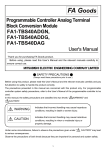
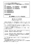
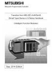
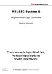
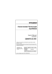
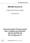
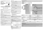
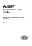
Programmable Controller Analog Terminal Block Conversion Module Programmable Controller High-Speed Counter Module Terminal Block Conversion Module FA Goods Model FA-LTB40ADG FA-LTB40DAG FA-LTB40ADGN FA-LTB40TDG FA-LTB40ADDG FA-LTB40RD3G FA-LTB40D63P6V5 FA-LTB40D63P6V12 FA-LTB40D63P6V24 FA-TB20TD FA-TB20TC User’s Manual SAFETY PRECAUTIONS (Always read these precautions prior to use.) Before using this product, please read this manual carefully and pay full attention to safety to ensure that the product is used correctly. The precautions presented in this manual are concerned with this product only. For programmable controller system safety precautions, refer to the user’s manual of the programmable controller to be used. In this manual, the ● SAFETY PRECAUTIONS ● are ranked as “DANGER“ and “CAUTION“. DANGER Indicates that incorrect handling may cause hazardous conditions, resulting in death or severe injury. CAUTION Indicates that incorrect handling may cause hazardous conditions, resulting in medium or minor injury and/or property damage. Note that failure to observe the CAUTION level instructions may lead to a serious consequence according to the circumstances. Always follow the precautions of both levels because they are important to personal safety. Please keep this manual in an easy-to-access location for future reference, and be sure to provide the manual to the end user. 1 [Installation Precautions] CAUTION Use this module in an environment that complies with the general specifications described in the catalog. Use in an environment outside the scope of general specifications may result in risk of electric shock, fire, malfunction, product damage, and deterioration. During installation, be sure to fully secure the module using a DIN rail or mounting screws and fully tighten the screws to the specified torque. Loosely tightened screws results in the risk of the module dropping and malfunction. Be careful to prevent foreign matter such as dust or wiring chips from entering the module. Failure to do so may result in the risk of fire, failure, and malfunction. Do not touch a powered terminal. Doing so results in the risk of malfunction. Do not directly touch a powered section of the module. Doing so results in the risk of module failure and malfunction. [Wiring Precautions] DANGER Be sure to shut off all phases of the external power supply used by the system before installation or wiring work. Failure to do so results in the risk of electric shock, module failure, and malfunction. CAUTION Be sure to ground the FG terminal by applying class D grounding (class 3 grounding) or higher. Failure to do so results in the risk of electric shock and malfunction. Correctly wire cables to the module after checking the rated voltage and terminal layout of the product. Connecting a power supply having a different rating or wiring the module incorrectly results in the risk of fire and malfunction. When wiring the input signal line and output signal line, do not bind the line with or have the line contact wiring having superimposed noise. Doing so results in the risk of malfunction. Tighten the terminal screws within the range of the specified torque. If a screw is too loose, a short circuit, or malfunction may result. If a screw is too tight, screw and/or module damage may result, causing the module to drop, a short circuit, or malfunction. 2 [Startup and Maintenance Precautions] DANGER Do not touch a terminal while the module is powered. Doing so results in the risk of electric shock and malfunction. Be sure to turn the power OFF before cleaning the module or retightening terminal screws. Failure to do so results in the risk of module failure and malfunction. CAUTION Do not disassemble or modify the module. Doing so results in the risk of failure, malfunction, injury, and fire. Be sure to shut off all phases of the external power supply module installation or removal. Failure to do so results in the risk of electric shock, module failure, and malfunction. [Disposal Precautions] DANGER At the time of disposal, treat the product as industrial waste. 3 INTRODUCTION Thank you for purchasing the FA Goods programmable controller analog terminal block conversion module and programmable controller high-speed counter module terminal block conversion module. Before using the product, please read this manual carefully to ensure correct and effective use. 1. PERFORMANCE SPECIFICATIONS FA-LTB40TDG Model name Item Thermocouple input terminal block conversion module FA-LTB40TDG Connectable module (Note 1) Q68TD-G-H01, Q68TD-G-H02 Connectable cable (Note 2) FA-CBL**Q68TDG Applicable wire: 0.5 to 1.25mm2 (conform to JIS C 2811 ) However, a 0.3 to 2mm2 cable is connectable by using an applicable crimping terminal. Terminal block (regular screws) Operating voltage: 8VDC or less, operating current: 1mA or less Terminal screw tightening torque range: 50 to 75N・cm (5.2 to 7.6kgf・cm) Terminal block screw: M3 screw Module Mounting screws mounting DIN rail M4 (with plain washer) x 0.7mm x 8mm or greater Tightening torque range: 78 to 118N・cm (8 to 12kgf・cm) Applicable DIN rail: TH35-7.5Fe, TH35-7.5Al (conform to JIS C 2812) Dielectric withstand voltage Between analog input CHs: 1000VAC for 1 minute; Other: 500VAC for 1 minute Insulation resistance (initial) 10MΩ or more by 500VDC insulation resistance tester Weight About 200g Note 1: Applies to the programmable controller MELSEC-Q series manufactured by Mitsubishi Electric Corporation. Note 2: The two asterisks (**) indicate cable length (05: 0.5m, 10: 1m, 20: 2m, 30: 3m). FA-TB20TD Model name Item Connectable module (Note 1) Connectable cable (Note 2) Thermocouple input terminal block conversion module FA-TB20TD Q64TD、Q64TDV-GH A1S68TD FA-CBLQ64TD** FA-CBLS68TD** 2 Applicable wire: 0.5 to 1.25mm (conform to JIS C 2811) However, a 0.3 to 2mm2 cable is connectable by using an applicable crimping terminal. Terminal block (Captive screws) Operating voltage: 5VDC or less operating current: 1mA or less Terminal block screw: M3 screw Terminal screw tightening torque range: 58.8 to 88.2N・cm (6 to 9kgf・cm) Terminal block screw pull force (axial direction): 78.4N or greater Module Mounting screws mounting DIN rail M4 x 0.7mm x 22mm or greater, tightening torque range: 78 to 118N・cm (8 to 12kgf・ cm) Applicable DIN rail: TH35-7.5Fe, TH35-7.5Al (conform to JIS C 2812) Dielectric withstand voltage 1500VAC (50/60Hz) for 1 minute Insulation resistance (initial) 100MΩ or more by 500VDC insulation resistance tester Weight 125g Note 1: Applies to the programmable controller MELSEC-Q series and AnS series manufactured by Mitsubishi Electric Corporation. Note 2: The two asterisks (**) indicate cable length (05: 0.5m, 10: 1m, 15:1.5m, 20: 2m, 25:2.5m, 30: 3m). 4 FA-TB20TC Model name Item Connectable module (Note 1) Connectable cable (Note 2) Temperature control terminal block conversion module FA-TB20TC Q64TCTT, Q64TCTTBW A1S64TCTRT, A1S64TCTRTBW FA-CBLQ64TC** FA-CBLS64TCTR** 2 Applicable wire: 0.5 to 1.25mm (conform to JIS C 2811) However, a 0.3 to 2mm2 cable is connectable by using an applicable crimping terminal. Terminal block (Captive screws) Operating voltage: 30VDC or less; Operating current: 400mA or less (common), 100mA or less (signal) Terminal block screw: M3 screw Terminal screw tightening torque range: 58.8 to 88.2N・cm (6 to 9kgf・cm) Terminal block screw pull force (axial direction): 78.4N or greater Module Mounting screws mounting DIN rail M4 x 0.7mm x 22mm or greater, tightening torque range: 78 to 118N・cm (8 to 12kgf・ cm) Applicable DIN rail: TH35-7.5Fe, TH35-7.5Al (conform to JIS C 2812) Dielectric withstand voltage 1500VAC (50/60Hz) for 1 minute Insulation resistance (initial) 100MΩ or more by 500VDC insulation resistance tester Weight 125g Note 1: Applies to the programmable controller MELSEC-Q series and AnS series manufactured by Mitsubishi Electric Corporation. Note 2: The two asterisks (**) indicate cable length (05: 0.5m, 10: 1m, 15: 1.5m, 20: 2m, 25:2.5m, 30: 3m). FA-LTB40RD3G Model name Item RTD input terminal block conversion module FA-LTB40RD3G Connectable module (Note 1) Q68RD3-G Connectable cable (Note 2) Terminal block (Regular screws) FA-CBL**Q68RD3G Applicable wire: 0.5 to 1.25mm2 (conform to JIS C 2811) However, a 0.3 to 2mm2 cable is connectable by using an applicable crimping terminal. Operating voltage: 8VDC or less, operating current: 1mA or less Terminal screw tightening torque range: 50 to 75N・cm (5.2 to 7.6kgf・cm) Terminal block screw: M3 screw Module Mounting screws mounting DIN rail M4 (with plain washer) x 0.7mm x 8mm or greater Tightening torque range: 78 to 118N・cm (8 to 12kgf・m) Applicable DIN rail: TH35-7.5Fe, TH35-7.5Al (conform to JIS C 2812) Dielectric withstand voltage Between analog input CHs: 1000VAC for 1 minute, Other: 500VAC for 1 minute Insulation resistance (initial) 10MΩ or more by 500VDC insulation resistance tester Weight About 200g Note 1: Applies to the programmable controller MELSEC-Q series manufactured by Mitsubishi Electric Corporation. Note 2: The two asterisks (**) indicate cable length (05: 0.5m, 10: 1m, 20: 2m, 30: 3m). 5 FA-LTB40ADG, FA-LTB40ADGN, FA-LTB40ADDG, FA-LTB40DAG Model name Q68AD-G conversion module FA-LTB40ADG Item Connectable module (Note 1) Connectable cable (Note 2) Terminal block (Regular screws) FA-LTB40ADGN Q66AD-DG conversion module Q66DA-G conversion module FA-LTB40ADDG FA-LTB40DAG Q66AD-DG Q66DA-G Q68AD-G FA-CBL**Q68ADG FA-CBL**Q68ADGN FA-CBL**Q66ADDG FA-CBL**Q66DAG Applicable wire: 0.5 to 1.25mm2 (conform to JIS C 2811) However, a 0.3 to 2mm2 cable is connectable by using an applicable crimping terminal. Terminal screw tightening torque range: 50 to 75N・cm (5.2 to 7.6kgf・cm) Terminal block screw: M3 screw Operating voltage 10VDC 10VDC 24VDC 24VDC Operating current 30mA or less 30mA or less 360mA or less 220mA or less Module Mounting screws mounting DIN rail M4 (with plain washer) x 0.7mm x 8mm or greater Tightening torque range: 78 to 118N・cm (8 to 12kgf・cm) Applicable DIN rail: TH35-7.5Fe, TH35-7.5Al (conform to JIS C 2812) Connector MIL40P Dielectric withstand voltage Between CHs: 1000VAC for 1 minute, Other: 500VAC for 1 minute Insulation resistance (initial) 10MΩ or more by 500VDC insulation resistance tester Weight About 200g Note 1: Applies to the programmable controller MELSEC-Q series manufactured by Mitsubishi Electric Corporation. Note 2: The two asterisks (**) indicate cable length (05: 0.5m, 10: 1m, 20: 2m, 30: 3m). FA-LTB40D63P6V5, FA-LTB40D63P6V12, FA-LTB40D63P6V24 QD63P6 terminal block conversion module Model name Item 5V signal input 12V signal input 24V signal input FA-LTB40D63P6V5 FA-LTB40D63P6V12 FA-LTB40D63P6V24 Connectable module (Note 1) Connectable cable (Note 2) QD63P6 FA-CBL**QD63P6 Applicable line: 0.5 to 1.25mm2 (conform to JIS C 2811) However, a 0.3 to 2mm2 cable is connectable by using an applicable crimping terminal. Terminal block (Regular screws) Terminal screw tightening torque range: 50 to 75N・cm (5.2 to 7.6kgf・cm) Terminal block screw: M3 screw Counter Voltage 5V±10% 12V±10% 24V±10% input signal Current 6.4 to 11.5mA 10.8 to 15.9mA 10.5 to 14.9mA Open collector output Open collector output Open collector output Connectable encoder CMOS voltage output M4 (with plain washer) x 0.7mm x 8mm or greater Module Mounting screws Tightening torque range: 78 to 118N・cm (8 to 12kgf・cm) mounting Applicable DIN rail: TH35-7.5Fe, TH35-7.5Al (conform to JIS C 2812) DIN rail Dielectric withstand voltage 500VAC for 1 minute Insulation resistance (initial) 10MΩ or more by 500VDC insulation resistance tester Weight About 200g Note 1: Applies to the programmable controller MELSEC-Q series manufactured by Mitsubishi Electric Corporation. Note 2: The two asterisks (**) indicate cable length (05: 0.5m, 10: 1m, 15:1.5m, 20: 2m). 6 2. EXTERNAL DIMENSIONS [unit: mm] Insulated thermocouple input terminal block conversion module (FA-LTB40TDG) Module Cable connector 191 181 169 mounting hole (44.7) 47 29 18 DIN rail Module mounting hole (4) 7.62 Input terminal block Simple lock (120 ° ) 14.3 5.5 Thermocouple input terminal block conversion module (FA-TB20TD) Module Cable connector 104 94 5 mounting hole 2-φ4.5 (32) 15 8.5 50 67.5 2-φ8 35.5 16 6 Module mounting (5) hole 5 DIN rail 12 7.62 Simple lock (120° ) Input terminal block Cold junction compensating resistor (supplied) 41.5 (3.2) Thermocouple input dedicated cable (For FA-CBL**Q68TDG MELSEC-Q series) Cable length: L Q68TD-G-H01 G68TD-G-H02 Connection side connector (6) (55.3) (18) φ7.4 (50) FA-LTB40TDG Connection side connector SLD SLD (300) (300) Shielded cable (with M4 round crimping terminal) Shielded cable (with M4 round crimping terminal) (For FA-CBLQ64TD** MELSEC-Q series) FA-TB20TD Cable length: L (22.8) FA-TB20TD (12.23) Connection side (22.8) FA-TB20TD side (12.23) Connection (50) connector 8 (51.03) φ10.0 Q64TD/Q64TDV-GH Q64TD/Q64TDV-GH Connection side terminal block (30) (For FA-CBLS68TD** MELSEC-AnS series) FA-TB20TD Cable length: L (50) connector (51.03) 10 φ10.0 A1S68TD A1S68TD Connection side terminal block (30) 7 Temperature control terminal block conversion module Module (FA-TB20TC) mounting hole (32) Cable connector 104 94 15 2-φ4.5 35.5 50 16 5 6 Module mounting (5) hole [Unit: mm] 5 DIN rail 8.5 2-φ8 Simple lock (120° ) 7.62 Input terminal block 12 41.5 (3.2) Temperature control cable with terminal block (For FA-CBLQ64TC** MELSEC-Q series) Q64TCTT/Q64TCTTBW Connection side terminal block FA-TB20TC Cable length: L (22.8) (12.23) Connection side connector 8 (51.03) φ10.0 (50) (150) (30) Shielded wire (with round crimping terminal) (For FA-CBLS64TCTR** MELSEC-AnS series) A1S64TCTRT/A1S64TCTRTBW Connection side terminal block FA-TB20TC Connection side connector Cable length: L (22.8) (50) (12.23) 10 (51.03) φ10.5 (30) (150) FG Insulated analog module terminal block conversion module, insulated RTD input module terminal block conversion module (FA-LTB40ADG/ADGN/ADDG/DAG, FA-LTB40RD3G) Module mounting hole (44.7) DIN rail Module mounting hole 7.62 Cable connector Input terminal block (4) 47 29 18 191 181 169 Simple lock (120° ) 14.3 5.5 Connection cable (FA-CBL**Q68ADG, FA-CBL**Q68ADGN, FA-CBL**Q66ADDG, FA-CBL**Q66DAG, FA-CBL**Q68RD3G) Cable length: L (6) (55.3) φ7.4 (50) (18) Q68RD3-G Q68AD-G Q66AD-DG Q66DA-G Connection side connector SLD SLD (300) Shielded wire (with M4 round crimping terminal) (300) Shielded wire (with M4 round crimping terminal) 8 FA-LTB40RD3G FA-LTB40ADG FA-LTB40ADGN FA-LTB40ADDG FA-LTB40DAG Connection side connector High-speed counter module terminal block conversion module (FA-LTB40D63P6V5/V12/V24) 191 181 169 [Unit: mm] Module mounting hole (44.7) 47 29 18 DIN rail 7.62 Cable connector (4) Module mounting hole Input terminal block Simple lock (120° ) 14.3 5.5 Connection cable (FA-CBL**QD63P6) Cable length: L QD63P6 Connection side connector (6) FA-LTB40D63P6V** Connection side connector (55.3) (7.4) (50) FG (200) High-speed counter module terminal block conversion module dedicated cable connection example Pulse generating device ** Phase A pulse input + Phase A Twisted shielded cable Shield Phase A pulse input - 5V signal 12V signal 24V signal Signal GND Phase B pulse input + Phase B Twisted shielded cable Shield Phase B pulse input - 9 5V signal 12V signal 24V signal Signal GND 3. INSTALLATION METHOD 3-1 Connecting the Connection Cable and Terminal Block Conversion Module with MELSEC-Q Series For MELSEC-Q series module with insulation between channels (Q68AD-G, Q66AD-DG, Q66DA-G, Q68TD-G-H01, Q68TD-G-H02, Q68RD3-G) Mitsubishi Electric Corporation MELSEC-Q series module with insulation between channels Q68AD-G Q66AD-DG Q66DA-G Q68TD-G-H01 Q68TD-G-H02 Q68RD3-G Q68TD-G RUN ALM ERR. Ground the FG wire in the same manner as the programmable controller module. Insert the connector to the back, and then fully install the connector to the programmable controller module using the mounting screws. Q68TD-G Connection cable FA-CBL**Q68ADG FA-CBL**Q68ADGN FA-CBL**Q66ADDG FA-CBL**Q66DAG FA-CBL**Q68TDG FA-CBL**Q68RD3G Ground the FG wire in the same manner as the programmable controller module. Insert the connector to the back, and then fully secure the connector with the clip. Terminal block conversion module FA-LTB40ADG FA-LTB40ADGN FA-LTB40ADDG FA-LTB40DAG FA-LTB40TDG FA-LTB40RD3G Voltage/Current input/output Dual wire transmitter input Thermocouple input RTD input 10 For MELSEC-Q series thermocouple input module [Q64TD, Q64TDV-GH, Q64TCTT (BW)] Q64TD RUN ERR. Q64TD Ground the FG wire in the same manner as the programmable controller module.(FA-CBLQ64T C** only.) For MELSEC-AnS series thermocouple input module [A1S68TD, A1S64TCTRT (BW)] MELSEC-Q series thermocouple input module manufactured by Mitsubishi Electric Corporation Q64TD Q64TDV-GH Q64TCTT(BW) MELSEC-AnS series thermocouple input module manufactured by Mitsubishi Electric Corporation A1S68TD A1S64TCTRT(BW) Ground the FG wire in the same manner as the programmable controller module.(FA-CBLS64T CTR** only.) Fully install the terminal block to the programmable controller module using the mounting screws. Fully install the terminal block to the programmable controller module using the mounting screws. Connection cable FA-CBLQ64TD** FA-CBLQ64TC** Connection cable FA-CBLS68TD** FA-CBLS64TCTR** Fully insert and secure the connector until you hear a click. Terminal block conversion module FA-TB20TD FA-TB20TC Fully insert and secure the connector until you hear a click. Terminal block conversion module FA-TB20TD FA-TB20TC Thermocouple input Temperature control input/output Thermocouple input Temperature control input/output 11 For MELSEC-Q series high-speed counter module (QD63P6) MELSEC-Q series counter module manufactured by Mitsubishi Electric Corporation QD63P6 QD63P6 RUN 1 2 3 4 5 6 CH φA φB ERR. Insert the connector to the back, and then fully install the connector to the programmable controller module using the mounting screws. QD63P6 Connection cable FA-CBL**QD63P6 Ground the FG wire in the same manner as the programmable controller module. Insert the connector to the back, and then fully secure the connector with a clip. Terminal block conversion module FA-LTB40D63P6V5 FA-LTB40D63P6V12 FA-LTB40D63P6V24 FA-LTB40D63P6V5 5V 12V 24V 12 Pulse input 3-2 Connecting the Terminal Block Conversion Module and External Devices FA-LTB40ADG 1 CH1 V+ 3 5 CH2 V+ - 2 CH1 V-/I- 4 CH1 I+ 7 CH2 V-/I6 Input2 Input3 Current input V+ 11 13 15 17 19 21 23 25 27 29 31 33 35 37 39 CH3 CH3 CH4 CH5 CH5 CH6 CH7 CH7 CH8 V+ I+ V-/IV+ I+ V-/IV+ I+ V-/I10 12 14 16 18 20 22 24 26 28 30 32 34 36 38 40 CH8 CH8 CH3 CH4 CH4 CH5 CH6 CH6 CH7 V-/IV+ I+ V-/IV+ I+ V-/IV+ I+ - 8 CH2 I+ - Input1 9 Input4 Input5 Input6 Input7 Input8 Voltage input I+ V+ V-/I- I+ V-/I- I- I+ V+ V- FA-LTB40ADGN 1 CH1 V+ 3 CH1 Is 2 CH1 V-/I- 5 CH2 V+ 4 CH1 I+ 7 CH2 Is 6 CH2 V-/I- Input1 9 11 13 15 17 19 21 23 25 27 29 31 33 35 37 39 CH3 CH3 CH4 CH4 CH5 CH5 CH6 CH6 CH7 CH7 CH8 CH8 V+ Is V+ Is V+ Is V+ Is V+ Is V+ Is 10 12 14 16 18 20 22 24 26 28 30 32 34 36 38 40 CH3 CH3 CH4 CH4 CH5 CH5 CH6 CH6 CH7 CH7 CH8 CH8 V-/II+ V-/II+ V-/I I+ V-/II+ V-/II+ V-/II+ - 8 CH2 I+ Input2 Current input(Note 1) V+ Input3 Is V+ V-/I- I+ I- I+ Input4 Input5 Input6 Input7 Input8 Voltage input(Note 2) Note 1: For current input, connect the (V+) and (Is) terminals. The screw terminal block short circuit bar FA-BAR20P can be used for the above connection. (For screw terminal block short circuit bar details, refer to our catalog.) Note 2: For voltage input, set the (Is) and (I+) terminals as NC, and do not connect external wiring. Is V-/I- I+ V+ V- FA-LTB40ADDG 1 CH1 P 3 5 I/CHK 2 4 I+ /CHK 7 CH2 P 9 11 13 15 17 19 21 23 25 27 29 31 33 35 37 39 ICH3 ICH4 ICH5 ICH6 IDC24V /CHK P /CHK P /CHK P /CHK P /CHK 8 10 12 14 16 18 20 22 24 26 28 30 32 34 36 38 40 I+ I+ I+ I+ I+ - DC24G /CHK /CHK /CHK /CHK /CHK 6 - Input1 Input2 Input3 P I-/CHK I+/CHK + - Dual wire transmitter Input5 Input6 24VDC Current input Dual wire transmitter input P Input4 I-/CHK I+/CHK + - I+ I- V FA-LTB40DAG 1 CH1 V+ 3 CH1 I+ 5 7 CH2 V+ - 9 CH2 I+ 11 - 2 4 6 8 10 COM1 - - COM2 - Output1 I+ COM V+ V- - Output2 Voltage output V+ 13 15 17 19 21 23 25 27 29 31 33 35 37 39 CH3 CH3 CH4 CH4 CH5 CH5 CH6 CH6 DC24V V+ I+ V+ I+ V+ I+ V+ I+ 12 14 16 18 20 22 24 26 28 30 32 34 36 38 40 COM3 Output3 - - COM4 Output4 Current output V+ I+ COM I- I+ 13 - - COM5 Output5 - - COM6 Output6 - - - DC24G 24VDC FA-LTB40TDG 1 CH1 + 3 5 CH2 + - 2 CH1 - 4 9 CH3 + - 6 CH2 - - Input1 7 8 - Input3 Input4 Input5 Input6 Input7 Input8 RTD · Install the module in a location having a constant ambient temperature. RTD input · Connect the thermocouple or compensation lead wire directly to the terminal RTDG block. (Note1) Thermocouple input + + 13 15 17 19 21 23 25 27 29 31 33 35 37 39 CH4 CH5 CH6 CH7 CH8 RTD + + + + + G 12 14 16 18 20 22 24 26 28 30 32 34 36 38 40 CH8 RTD RTD CH4 CH5 CH6 CH7 + - 10 CH3 - - Input2 11 - RTD+ RTD- - RTD (Note1) FA-LTB40RD3G 1 CH1 A1 3 CH1 b1 2 CH1 B1 5 7 CH2 B2 4 6 CH2 A2 - Input1 9 Note 1: For the cold junction compensating resistor (RTD), connect the supplied Q68TD-G-H01 and -H02 products to terminal numbers 38 and 40 as illustrated above. Terminal number 38 (RTD G) and terminal number 40 (RTD -) are connected inside the conversion module, and therefore do not require external wiring. 11 13 15 17 19 21 23 25 27 29 31 33 35 37 39 CH3 CH3 CH4 CH5 CH5 CH6 CH7 CH7 CH8 B4 A5 b5 B6 A7 b7 B8 A3 b3 10 12 14 16 18 20 22 24 26 28 30 32 34 36 38 40 CH8 CH8 CH3 CH4 CH4 CH5 CH6 CH6 CH7 B3 A4 b4 B5 A6 b6 B7 A8 b8 - 8 CH2 b2 Input2 Input3 Input4 Input5 Input6 Input7 Input8 RTD input A B b A B A B b b A B b FA-TB20TD(With Q64TD and Q64TDV-GH connection) Input2 1 3 5 7 - - - SLD 2 RTD + 4 RTD - 6 SLD Thermocouple input + 11 13 15 17 19 CH2 CH4 CH4 SLD + 10 12 14 16 18 20 CH1 CH3 CH3 SLD + - Input1 Input3 RTD input RTD+ RTDRTD - + (Note2) FA-TB20TD(With A1S68TD connection) Input1 9 CH2 + 8 CH1 + RTD Input4 1 CH1 + Input2 3 CH1 - 2 RTD + 5 CH2 + 4 RTD - Input4 7 CH2 - 6 CH3 + Input6 Input8 9 CH4 + 8 CH3 - 11 13 15 17 19 CH4 CH6 CH6 CH8 CH8 + + 10 12 14 16 18 20 CH5 CH5 CH7 CH7 SLD SLD + + - RTD Input3 Input5 Input7 · Install the module in a location having a constant ambient temperature. · Connect the thermocouple or compensation lead wire directly to the terminal block. · For FA-CBLQ64TD** and FA-CBLS68TD**, a ground wire is not wired. Grounding with FA-TB20TD is not possible. Ground Q64TD with terminal number 18 of the programmable controller module side terminal block of FA-CBLQ64TD. Ground A1S68TD with terminal number 20 of the programmable controller module side terminal block of FA-CBLS68TD**. Note 2: The cold junction compensating resistor (RTD) is supplied with FA-TB20TD. FA-TB20TC(With Q64TCTT(BW) connection) Input1 Control output 1 3 L1 5 COM - L3 7 CH1 + 2 4 6 L2 L4 - Control output Input3 9 CH1 - 8 CH2 + 15 17 19 CH3 CH3 + 10 12 14 16 18 20 CH2 CH4 CH4 + - Input2 11 Thermocouple input + - + - 13 Input4 · Install the module in a location having a constant ambient temperature. · Connect the thermocouple or compensation lead wire directly to the terminal block. · The cold junction compensating resistor (RTD) is built into FA-TB20TC. 14 FA-TB20TC(With A1S64TCTRT(BW) connection : Standard Control (thermocouple)) Input1 Control output 1 3 L1 L3 5 COM - 7 2 4 6 L4 - 8 CH2 + Thermocouple input Monitor input - + - 11 13 15 17 19 CH1 CH3 CH3 + 10 12 14 16 18 20 CH2 CH4 CH4 + - FA-TB20TC (With A1S64TCTRT (BW) connection : Standard control (platinum RTD)) Input1 Control output 1 3 L1 L3 5 COM - 2 4 L2 L4 7 CH1 A 6 CH2 A Control output Platinum RTD input Monitor input - A B b A B b 8 CH2 B 3 5 7 CH1 CH1 A+(5) B+(5) 2 4 6 CH1 CH1 AB- 3 5 7 CH1 CH1 A+(12) B+(12) 2 4 6 CH1 CH1 AB- 3 5 7 CH1 CH1 A+(24) B+(24) 2 4 6 CH1 CH1 AB- Input1 9 MT1 + - 2 4 6 L1C L2C - 8 CH1 + 11 13 15 17 19 MT1 MT2 MT2 + 10 12 14 16 18 20 CH1 CH2 CH2 + - Input2 MonitorInput1 Control output 1 3 L1H L2H 5 COM - 2 4 L1C L2C 7 MT1 A 6 CH1 A MonitorInput2 9 MT1 B 8 CH1 B 11 13 15 17 19 MT1 MT2 MT2 MT2 A B b b 10 12 14 16 18 20 CH1 CH2 CH2 CH2 A B b b Input2 (For 5V signal) Input2 Input3 Input4 Input5 Input6 (For 12V signal) 9 11 13 15 17 19 21 23 25 27 29 31 33 35 37 39 CH2 CH2 CH3 CH3 CH4 CH4 CH5 CH5 CH6 CH6 A+(12) B+(12) A+(12) B+(12) A+(12) B+(12) A+(12) B+(12) A+(12) B+(12) 8 10 12 14 16 18 20 22 24 26 28 30 32 34 36 38 40 CH2 CH2 CH3 CH3 CH4 CH4 CH5 CH5 CH6 CH6 ABABABABAB- Input2 FA-LTB40D63P6V24 - 7 9 11 13 15 17 19 21 23 25 27 29 31 33 35 37 39 CH2 CH2 CH3 CH3 CH4 CH4 CH5 CH5 CH6 CH6 A+(5) B+(5) A+(5) B+(5) A+(5) B+(5) A+(5) B+(5) A+(5) B+(5) 8 10 12 14 16 18 20 22 24 26 28 30 32 34 36 38 40 CH2 CH2 CH3 CH3 CH4 CH4 CH5 CH5 CH6 CH6 ABABABABAB- Input1 1 Input3 11 13 15 17 19 CH1 CH3 CH3 CH3 A B b b 10 12 14 16 18 20 CH2 CH4 CH4 CH4 b A B b FA-LTB40D63P6V12 - 5 COM - Control output Input1 Input4 Input2 · Install the module in a location having a constant ambient temperature. · Connect the thermocouple or compensation lead wire directly to the terminal block. · The cold junction compensating resistor (RTD) is built into FA-TB20TC. Input1 1 3 L2H FA-TB20TC (With A1S64TCTRT (BW) connection : Heating and cooling control (platinum RTD)) 9 CH1 B FA-LTB40D63P6V5 1 1 L1H Monitor Input2 Control output Input1 Input4 Input2 · Install the module in a location having a constant ambient temperature. · Connect the thermocouple or compensation lead wire directly to the terminal block. · The cold junction compensating resistor (RTD) is built into FA-TB20TC. Control output + Monitor Input1 Control output Input3 9 CH1 + - L2 FA-TB20TC (with A1S64TCTRT (BW) connection : Heating and cooling Control (thermocouple)) Input3 Input4 Input5 Input6 (For 24V signal) 9 11 13 15 17 19 21 23 25 27 29 31 33 35 37 39 CH2 CH2 CH3 CH3 CH4 CH4 CH5 CH5 CH6 CH6 A+(24) B+(24) A+(24) B+(24) A+(24) B+(24) A+(24) B+(24) A+(24) B+(24) 8 10 12 14 16 18 20 22 24 26 28 30 32 34 36 38 40 CH2 CH2 CH3 CH3 CH4 CH4 CH5 CH5 CH6 CH6 ABABABABAB- Input2 Input3 Input4 15 Input5 Input6 Pulse input A+ B+ A- B- + - + Phase A Phase B 4. USAGE PRECAUTIONS (1) For wiring to the terminal block, refer to the manual of the programmable controller module to be connected, published by Mitsubishi Electric Corporation. (2) Ground the FG wire provided with the cable in the same manner as the programmable controller module. Note that rolling up extra wire without grounding the wire may cause the wire to function as an antenna, resulting in the risk of noise. For Your Safety This product has been manufactured as a general-purpose product for general industry applications, etc. The product is not intended for use in devices or systems used under conditions in which human life could be greatly affected. When considering application of this product to special applications, such as nuclear power, electrical power, aerospace, medical, or manned transport devices or systems, contact our sales service desk. Although this product was manufactured under a strict quality management system, the product shall be systematically provided with backup and fail-safe functions when applied to equipment that may lead to a major accident or damage in the unlikely event any failure or defect should occur in the product. MITSUBISHI ELECTRIC ENGINEERING CO., LTD. 1-13-5 Kudankita, Chiyoda-ku, Tokyo, Japan 102-0073 Homepage URL: http://www.mee.co.jp/ Direct any technical inquiries to: Nagoya office (PC Engineering Dept.) Phone: +81 (52) 723-8058 Fax: +82 (52) 723-8062 During product use, be sure to ensure safety in the unlikely event failure occurs. Mitsubishi Electric Engineering assumes no responsibility whatsoever for any secondary damage caused by the failure of this product. 50D-FB0035 (0906) MEE Information such as specifications is subject to change without notice. Developed June 2009 16