1
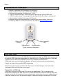
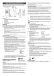
GSM Mi ni
SMS-operated 230V Socket
User manual
CEE 7/4 « Schuko » Edition
OVERVIEW OF GSM MINI .................................................................................................. 2
BEFORE USE....................................................................................................................... 2
Preparation of SIM card ................................................................................................... 2
Inserting the SIM card ...................................................................................................... 3
Start-up.............................................................................................................................. 3
Signal strength .................................................................................................................. 3
Reset of personal access code........................................................................................ 3
SMS CONTROL ................................................................................................................... 4
Sending SMS messages.................................................................................................. 4
CONTROL COMMANDS ..................................................................................................... 4
R
S
C
T
M
P
U
for switching the Relay (output socket) on/off.......................................................... 4
for requesting a Status message per SMS .............................................................. 4
for changing the personal access Code................................................................... 4
for Timer control (hourly countdown)........................................................................ 5
for timer control by Minutes....................................................................................... 5
for producing a Pulse ................................................................................................ 5
for resetting e.g. a PC ............................................................................................... 5
PRECONDITIONS AND ADVICE ....................................................................................... 6
Troubleshooting ................................................................................................................ 6
TECHNICAL SPECIFICATIONS ......................................................................................... 7
WARRANTY ......................................................................................................................... 8
RECYCLING ......................................................................................................................... 8
R
Schuko Edition
Copyright © 2009, Hulaas IT Solutions
www.EcoStarter.com
Page 2
OVERVIEW OF GSM MINI
•
•
•
•
•
•
•
•
Based on standard GSM networks. Quad-band.
Relay (output socket) rating: 230V 16A, 3600W.
Personal access code. Factory set to “1234”.
1 LED for signal strength. A blinking green light signals a faulty SIM card.
1 LED for relay status. A steady green light signals that the relay is switched on.
1 push-button to switch the relay on/off locally.
Remote control with the possibility to retrieve the current status of the unit.
Control by SMS or by Internet (discover the offer at www.EcoStarter.com).
Signal strength
LED
Status LED
(“Relay”)
SIM card slot
On/Off switch
(both on bottom faceplate)
BEFORE USE
All remote communication with GSM Mini takes place through the GSM network. In order
to receive SMS command messages (for controlling e.g. a heating appliance), GSM Mini
needs to have a SIM card installed, just like any standard mobile phone.
SIM cards from any mobile phone operator will work, both pre-pay and subscription
based, as long as they enable SMS messaging.
Remember that pre-pay solutions will often have a limited life span, and need to be
recharged with credit at least once a year.
Preparation of SIM card
GSM Mini requires the SIM card PIN code to be deactivated. This is carried out by
temporarily inserting the SIM card into a normal GSM mobile phone where the PIN code
can be turned off via its security menu (please refer to the manual of your mobile phone).
After this, when you turn the phone on again, it should no longer request this PIN code.
Page 3
NB! It has become common that mobile phones are locked to a specific operator, i.e. that
they will only accept SIM cards from the operator that sold the phone. Hence you may be
unable to use your mobile phone to deactivate the PIN code of the SIM card intended for
the GSM Mini if this new SIM card is not from the same operator as the phone. In such a
case, you will have to borrow a phone from someone else or get help in a mobile phone
shop.
Inserting the SIM card
Always ensure that GSM Mini is powered off (i.e., it is not plugged into a socket) when
manipulating the SIM card. Insert the SIM-card into GSM Mini as shown in the picture
below, with the clipped corner to the left and the gold contacts down. Push the SIM-card
inwards until you hear a "click". Similarly, to later take the card out, gently push until you
hear a "click".
Start-up
When GSM Mini is plugged into the wall socket (and its SIM card has been activated),
the Signal LED will first turn green after 5 seconds. Then GSM Mini will continue the
start-up procedure and be ready for use after about 15 seconds.
Signal strength
The Signal LED shows the strength of the GSM signal, as follows:
1. Green:
Good signal.
2. Red:
Medium quality signal.
3. Off (no light):
Bad or no signal.
In case situation (2) or (3) occurs, the antenna should be re-oriented for better coverage.
Reset of personal access code
GSM Mini is factory set with “1234” as personal access code. Should you lose or forget
your code, the following procedure will reset it to “1234”:
•
Pull GSM Mini out of the wall socket
•
Press and hold the on/off switch on the bottom faceplate
•
Plug GSM Mini into the wall socket and continue to hold the switch for another
5-10 seconds before releasing it
•
Access code is now set back to “1234”
Page 4
SMS CONTROL
GSM Mini is configured and controlled using regular SMS messages sent from mobile
phones. The factory-set personal access code “1234” will be used in the following
examples. You should set a new access code as soon as possible – and remember it!
Sending SMS messages
SMS messages must always contain the following:
•
First, the 4-digit access code
•
Then, any control commands (several can be sent in the same SMS)
“” (quotation marks) shall not be written in the SMS.
Send the SMS messages to your GSM MINI by using the phone number of the SIM card
inside the GSM Mini.
CONTROL COMMANDS
R
for switching the Relay (output socket) on/off
R is followed by 1 for on or 0 for off.
E.g.:
E.g.:
“1234 R1” switches on the relay (output socket) of GSM Mini.
“1234 R0” switches off the relay (output socket) of GSM Mini.
S
for requesting a Status message per SMS
The S command makes GSM Mini reply with a status message returned by SMS.
E.g.:
“1234 S” obtains current status by SMS.
The returned status message will usually be like this:
Either “Relay On” or “Relay Off”, followed by
“Sikom GSM Mini V1.0 Telit” (software version of GSM Mini).
If timer control is active, the status message will be like this:
Example 1: “Relay 02Tim” (relay is on, with 2 hours left)
Example 2: “Relay 04Min” (relay is on, with 4 minutes left)
followed by “Sikom GSM Mini V1.0 Telit” (software version of GSM Mini).
C
for changing the personal access Code
Change the current personal access code to a new 4-digit value.
E.g.:
“1234 C9898” changes the code from 1234 to 9898.
NB: Remember the new code!
Page 5
T
for Timer control (hourly countdown)
The relay (output socket) can be turned on for a programmable duration, between 1 and
99 hours.
T is followed by the desired number of hours (always a 2-digit value: 01 = 1 hour, 05 = 5
hours, etc.)
E.g.:
E.g.:
“1234 T01” switches relay on for 1 hour.
“1234 T11” switches relay on for 11 hours.
If necessary, use the R command to interrupt before the end of the countdown.
E.g.:
M
“1234 R0” switches relay off (i.e. it cuts the power) and ends timer control.
for timer control by Minutes
The relay (output socket) can be switched on for a programmable duration, between 1
and 99 minutes.
M is followed by the desired number of minutes (always a 2-digit value: 05 = 5 minutes,
etc.)
E.g.:
E.g.:
“1234 M01” switches relay on for 1 minute.
“1234 M11” switches relay on for 11 minutes.
If necessary, use the R command to interrupt before the end of the countdown.
NB! The timer has an error margin of about 1 minute. Therefore, if timer is set to 1
minute, GSM Mini may switch off the relay after just a few seconds.
P
for producing a Pulse
Switch relay on for a chosen number of seconds (between 1 and 9) and then off again.
E.g.:
“1234 P1” switches relay on for 1 second, and then off.
NB! This command will cancel any active timer control.
U
for resetting e.g. a PC
Switch relay off for a chosen number of seconds (between 1 and 9) and then on again.
E.g.:
“1234 U1” switches relay off for 1 second, and then on.
NB! This command will cancel any active timer control.
Page 6
PRECONDITIONS AND ADVICE
For GSM Mini to work satisfactorily, a good coverage of the relevant GSM network is
needed. The reliability of SMS messaging depends on the network operator. An SMS will
not be delivered in case of errors on the GSM network, or similar issues under the
responsibility of the operator. When the GSM network is heavily loaded, it may take
several minutes (or even hours) for an SMS message to be delivered. These are
conditions that Sikom AS cannot do anything about. The dispatch date and time of the
message are nevertheless visible at delivery.
If you opt for a prepay solution, remember that the credit must be recharged before use.
Information on this procedure comes with the SIM card. GSM Mini is unable to warn if the
credit gets exhausted, as no SMS message may then be sent out.
In conformance with legal regulations, network operators are free to cease certain GSM
services. Sikom AS is not a provider of GSM services and can therefore not be held
liable for any changes of such services. Notifications should nevertheless be published
long before such events take place.
Troubleshooting
No light from any LED:
•
Check your power supply, circuit breakers and fuses. Try another power socket.
Signal LED flashes green:
•
Is the SIM card subscription valid?
•
SIM card PIN code must be deactivated.
Signal LED flashes red:
•
Wait about 2-3 minutes for GSM Mini to restart on its own.
•
If it’s still blinking: pull GSM Mini out of the wall socket and wait 1 minute before
you put it back into the wall socket.
•
The red blinking can signal a faulty GSM Mini: contact your dealer.
GSM Mini does not reply to requests for status SMS:
•
Is the SIM card subscription valid and paid for?
Important info
Do not overload GSM Mini, and do not place it in confined places, which may lead to
overheating. When overheated, Relay LED will keep flashing red/green, and the relay will
be switched off. GSM Mini may then only be reset on site, by hand, as follows:
1. Pull GSM Mini out of the wall socket. Remove any excessive load connected to it.
2. Wait 1 minute.
3. Put GSM Mini back into socket.
4. Check that the total power consumption of connected appliances (e.g., heaters)
does not exceed the rated power of GSM Mini (see technical specifications
below).
For all other errors, please take a look at the FAQ at www.EcoStarter.com
Page 7
TECHNICAL SPECIFICATIONS
Manufacturer:
Model:
GSM standard:
Operating voltage:
Max load:
Power consumption:
Operating temperature:
Dimensions (LxHxD):
Weight:
Sikom AS, Norway
GSM Mini, CEE 7/4 « Schuko » execution
Quadband (850, 900, 1800, 1900 MHz)
230VAC
3600W (230V/16A)
Max 10W
-20ºC to 50ºC
58 x 120 x 47 mm
300g
GSM Mini is designed for indoor use only.
This equipment complies with the European R&TTE directive. Further information may
be obtained by contacting either the importer or the manufacturer:
Sikom AS
Jernbanegata 16/18
P.O. Box 223
7601 Levanger
Norway
Internet address: www.sikom.no
Page 8
WARRANTY
Sikom AS products are covered by a two years warranty against any faults due to
material flaws or manufacturing errors, which limit or render useless certain functions
described for the product. The warranty requires the customer to present the original bill,
with date of purchase and type of equipment clearly readable.
What is covered by the warranty?
During the warranty period, Sikom AS reserves the right to repair the product or to
replace defective parts with functionally equivalent parts. If, after several attempts, Sikom
AS is unable to correct the problem, and the product does not work as described in the
manual, Sikom may elect to refund the purchase price or to replace the product with a
functionally equivalent one. All replaced parts and products become the property of
Sikom AS.
What is not covered by the warranty?
• Indirect damage to life, health, property, revenue and environment caused by circuits
and appliances connected to the units (install and use this product responsibly).
• Costs related to (re)installing, transporting and dismantling units; recycling may be
governed by special rules (see the relevant chapter below).
• Damages caused by use outside of the operating conditions specified in the manual.
• Malfunctions caused by transport damages.
• Any unauthorized repair, modification or disassembly.
• Use of non-original parts.
• External factors, such as lightning, power supply issues, mobile network issues,
flood damage or fire.
• Units with modified, removed or unreadable serial number.
RECYCLING
Waste Electrical and Electronic Equipment (WEEE) information:
The WEEE symbol indicates that this product must not be disposed of along with other
household waste. It is the customer's responsibility to dispose of the product properly by
taking it to a designated site for recycling. To locate a recycling/disposal site near you,
contact your local city recycling program, your regular waste disposal service or the
agent from whom you purchased this product.
Sikom and its dealers assume no responsibility for any errors that may appear in this
manual. Information contained herein is subject to change without notice.