1
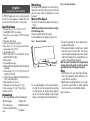
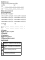
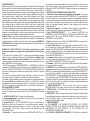
PTK5507
v1.0
Installation Instructions
WARNING: Please refer to the System Installation Manual for information on limitations regarding product use and function and information on the limitations as to liability of the manufacturer.
NOTE: These instructions shall be used in conjunction with the system Installation Manual of the Control Panel with which this equipment is intended to be used.
Mounting
English
Installation Instructions
The PTK5507 keypad can be used on security systems with
up to 64 zones. These keypads are compatible with the latest version of the Power Series V4.2+security systems.
Specifications
• Temperature range: -10°C to +55°C (14°F to 131°F)
• Humidity (MAX): 93%R.H. non-condensing
• Plastic enclosure protection degree: IP30, IK04 (touchscreen
excluded)
• Voltage rating: 12VDC nominal
• Connects to control panel via 4-wire Keybus
• Keybus distance: 60 m (200 ft.) (max.); keybus distance in
extra power mode: 33.5 m (110 ft)
• Up to 8 keypads per system
• PTK5507 Current draw: 200 mA (standby)/300 mA (activated)/ 400mA Extra Power Mode
• Wall mount tamper
• 5 programmable function keys
• Ready (Green LED), Armed (Red LED), Trouble (Yellow LED), AC
(Green LED)
• Touchscreen display: 8.5" x 5.1" x 0.8" [127.9 mm (L) x 195
mm (W) x 20.35 mm (D)]
• SD card slot: holds any standard Secure Digital (SD) card (32 x
24 x 2.1 mm) containing photos
• Wiring: standard four-wire connection
• Viewing angle: horizontal viewing angle: 50° (typ.)
• Vertical viewing angle: 70° (top), 70° (bottom) (typ.)
• Brightness: 280 cd/m2
Unpacking
The Power keypad package includes the following parts:
•One Power keypad
•1 tamper switch
•Five mounting screws
•Installation Instructions
•Five anchors for wall-mounting •User Manual
screws
Figure 2 - Mounting the backplate
You should mount the keypad where it is accessible to designated points of entry and exit. Once you have selected a dry
and secure location, perform the following steps to mount
the keypad.
Mount and Wire Keypad
1. Remove the SD card before opening the touchscreen (see
Figure 1).
WARNING: Disassembling the touchscreen without removing the
SD card will damage the unit.
2. Remove screw at the bottom of the keypad.
3. Insert screwdriver into slots and pry up to remove cover.
Figure 1 - Removing the backplate
5. Run wire through wiring slot. Connect keybus wiring to
keypad (see Wiring section).
6. Place keypad into backplate, ensuring the wire is pushed
back into the wall as much as possible. Route the wire
inside the keypad ensuring high components are avoided.
Snap the front assembly closed, ensuring that there is no
pressure to the keypad from the wire below.
NOTE: If any tension is found between the front keypad assembly
and wiring, please open the keypad, re-route the wire and close
again. Repeat these steps until the keypad is closed properly.
Wiring
4. Secure keypad backplate to wall using mounting holes.
(See Figure 2.) Use all 4 screws provided unless mounting
on a single gang box. Use the plastic anchors supplied if
the unit is to be mounted on drywall. If using the keypad
tamper, secure the tamper plate to the wall with a screw.
1. Before wiring the unit, ensure that all power (AC transformer, telecommunication network, and battery) is disconnected from the control panel.
2. Wrap the Keybus wires through the ferrite core (see Figure
3); one turn is enough. The ferrite core shall be installed as
close to the touchscreen as the installation will allow.
Figure 3 - Ferrite core
3. Connect the four Keybus wires from the control panel
(green, yellow, black, and red) to the keypad terminals.
Refer to Figure 4.
Figure 4 - Wiring
PTK5507
NOT USED
GRN
YEL
BLK
RED
Applying Power
Once all wiring is complete, and the equipment is secured to
the building structure with at least two screws, apply power
to the control panel:
1. Connect the battery leads to the battery.
2. Connect the AC transformer.
3. Connect telecommunication network.
For more information on control panel power specifications,
see the control panel Installation Manual.
CAUTION: Route all the wiring according to the local codes and
regulations.
Programming the Keypad
There are sevToggle Option
eral programming options
1_ _ 4 _ _ _ _
available for
the keypad.
These are described below. Programming the keypad is similar to programming the rest of the system. When you are in
the keypad programming sections, the keypad will display
which options are turned on. To turn an option on or off,
press the number corresponding to the option on the number
pad. The numbers of the options that are currently turned
ON will be displayed. For example, if options 1 and 4 are
on, the display will look like the diagram shown.
For information on programming the rest of your security
system, please refer to your system’s Installation Manual.
NOTE: Do not enable keypad blanking (panel programming,
section 016, option 3). If keypad blanking is enabled, the panel
will stop sending out the status and the keypad status will be
inaccurate.
Enrolling the Keypad
The keypad will need to be assigned to a partition and slot if
supervision or keypad zones are being used. Keypad
assignments and keypad option programming must be done
at each keypad individually.
The 1st digit of keypad assignment is used to determine
partition assignment (1 to 8). If partitioning is not used,
enter [1]. For Global Keypads, enter [0].
The 2nd digit of keypad assignment is used to determine
slot assignment for keypad supervision. Each keypad will be
assigned a different slot number from 1 to 8.
Enter the following at each keypad installed on the system:
1. Enter Installer Programming by pressing Options, Installer
Menu [Installer Code], then Keypad Mode Prog.
2. Press [000] for keypad programming.
3. Press [0] for Partition and Slot Assignment.
4. Enter the 1st digit (0 to 8 for partition assignment).
5. Enter the 2nd digit (1 to 8 for slot assignment supervision).
6. Press the [#] key twice to exit programming.
7. After assigning all keypads, perform a supervisory reset by
entering Options, Installer Menu, [Installer’s Code], [902],
and waiting for 60 seconds.
8. Press the [#] key to exit programming after 60 seconds.
Programming Labels
1. Enter Options, Installer Menu [Installer Code], then Label
Programming.
2. Select the desired Label to Program.
3. Using the keyboard on the screen, enter the new label and
press save when complete.
Broadcasting LCD Labels
All LCD programming is done per keypad. If more than one
LCD keypad is present on the system, labels programmed at
one keypad can be broadcast to all other LCD keypads. Perform the following procedure in order to broadcast labels:
Step 1 - Program one LCD keypad completely.
Step 2 - Make sure all LCD keypads are connected to the Keybus.
Step 3 - Enter keypad programming by pressing Options,
Installer Menu [Installer Code], Keypad Mode Prog, then enter
section [,] [998] [,] at the keypad that was programmed.
The keypad will now broadcast all the information programmed to all the other LCD keypads on the system.
Step 4 - When the keypad is finished press the [#] key to exit.
ASCII Characters
Changing Backlight (Brightness Level)
1. Press Options, Keypad Config, then Backlight.
2. Use slide bar to adjust brightness to desired setting.
3. Press the Back or Home button.
Changing the Buzzer Level
1. Press Options, Keypad Config, then Buzzer Control.
2. Use slide bar to adjust buzzer to desired setting.
3. Press the Back or Home button.
Entering Calibration Mode
1. Press Options, Keypad Config, then Calibration.
2. Press the cross hairs on the screen to complete calibration.
NOTE: Calibration mode can also be entered by pressing and
holding the home button for 3 seconds.
Changing the Background Image
1. Press Options, Installer Menu [Installer Code], Keypad Programming, then Background Image.
2. Select image to use image from SD card as background
image.
3. To exit, press Back or Home button.
Dark Text Enable/Disable
1. Press Options, Installer Menu [Installer Code], Keypad Programming, then Options.
2. Select the desired text color by enabling or disabling Dark Text. (Disabling makes the text
white.)
NOTE: This feature affects only the text on the Classic (Square) Button Home Page.
Changing Home Page Look:
1. Press Options, Keypad Config, Home Page.
2. Select the desired view from either classic look (square) or contemporary (rondel).
3. To exit, press the Back or Home button.
Performing a Firmware Upgrade:
1. Insert an SD card in the PTK5507 with the new firmware.
2. Press Options, Installer Menu [Installer Code], Keypad Programming, then Firmware
Upgrade.
3. Select OK to perform a firmware update (if a new firmware version is available).
Enabling/Disabling Fire, Auxiliary and Panic Buttons
1. Press Options, Installer Menu [Installer Code], Keypad Programming, then Options.
2. Enable/disable the desired Fire, Auxiliary and Panic buttons.
NOTE: The Fire, Auxiliary and Panic buttons are enabled by default on the PTK5507.
Extra Power Option
The Extra Power option will increase the brightness of the display. To enable the option:
1. Press Options, Installer Menu [Installer Code], Keypad Programming, then Options.
2. Enable or disable the extra power option.
NOTE: Enabling the Extra Power option will put the keypad in a higher current mode and the keypad will draw 400 mA.
Changing Function Keys on the Home Page:
1. Press Options, Installer Menu [Installer Code], Keypad Programming, then Home Functions.
2. Assign the desired function to the corresponding key.
3. To exit press the Back or Home button.
Adjusting Screen Time out
1. Press Options, Keypad Config, then Backlight.
2. Select appropriate time for screen time out by using the slide bar.
3. To exit, press Back or Home button.
Accessing Clean Mode
Press Options, Keypad Config, Clean Mode.
NOTE: Clean mode will time out in 30 seconds.
Keypad Enrollment
Enter keypad programming by pressing Options, Installer Menu [Installer’s Code], Keypad
Mode Prog, then [000].
[0] Partition / Slot Assignment
Digit
Option
Valid Range Default
1st Partition Assignment (0=Global Keypad) 0 to 8
1
I_____I
2nd
Slot Assignment
1 to 8
8
I_____I
[1]-[5] Function Key Assignment
Do not attempt to change the function key programming or the home page buttons may not
function as desired.
Keypad Programming
Enter keypad programming by pressing Options, Installer Menu [Installer’s Code], Keypad
Mode Prog, then [000].
[001]-[064] Zone Label 1 to 64
ex. For Zone 1 enter section [001], for Zone 2 enter section [002] etc. Default: “Zone 1”-“Zone 64”
Label
[001] 1 to I_____I_____I_____I_____I_____I_____I_____I_____I_____I_____I_____I_____I_____I____I
to
[064] 64 I_____I_____I_____I_____I_____I_____I_____I_____I_____I_____I_____I_____I_____I____I
[077] Second Keypad Options
Default
Option
ON
OFF
Chime Enabled for Zone
Chime Disabled for Zone
ON
I____I 1
Openings
Openings
Chime Enabled for Zone
Chime Disabled for Zone
ON
I____I 2
Closings
Closings
For Future Use
OFF I____I 3
For Future Use
ON
I____I 4
For Future Use
OFF I____I 5
For Future Use
ON
I____I 6
For Future Use
ON
I____I 7
For Future Use
OFF I____I 8
Section Zone
NOTE: Do not attempt to change options 3-8 in Section 077 or the keypad may not function as
desired.
[101]-[108] Partition Labels
ex. For Partition 1 enter section [101], for Partition 2 enter section [102] etc.
Section Partition
Label
[101]
I_____I_____I_____I_____I_____I_____I_____I_____I_____I_____I_____I_____I_____I_____I
to
1 to 8
I_____I_____I_____I_____I_____I_____I_____I_____I_____I_____I_____I_____I_____I_____I
[108]
NOTE: Partition 1 Label is also used as the System Label
[120]-[151] Command Output Labels
Default: “Command_O/P_1” - “Command_O/P_4”
For Partition 1 Command O/P 1 to 4 enter [120] to [123]
For Partition 2 Command O/P 1 to 4 enter [124] to [127]
For Partition 3 Command O/P 1 to 4 enter [128] to [131]
For Partition 4 Command O/P 1 to 4 enter [132] to [135]
For Partition 5 Command O/P 1 to 4 enter [136] to [139]
For Partition 6 Command O/P 1 to 4 enter [140] to [143]
For Partition 7 Command O/P 1 to 4 enter [144] to [147]
For Partition 8 Command O/P 1 to 4 enter [148] to [151]
Cmd.
Section Part Output
Label
I
_
_
_
_
_
I
_
_
_
_
_
I
_
_
_
_
_
I
_
_
_
_
_
I
_
_
_
_
_
I
_
_
_
_
_
I
_
_
_
_
_I_____I_____I_____I_____I_____I_____I_____I
[120]- 1 to 1 to
[151] 8
4 I_____I_____I_____I_____I_____I_____I_____I_____I_____I_____I_____I_____I_____I_____I
[994] For Future Use
[995][,] Reset Keypad Options to Factory Default
[996][,] Label Default
[997] View Software Version
[998][,] Initiate Global Label Broadcast
[999][,] Reset Keypad EEPROM to Factory Defaults
Keypad Display Symbols
Ready Light (green) – If the Ready light is on, the system is ready for arming.
Armed Light (red) – If the Armed light is on, the system has been armed successfully.
System Trouble – Indicates that a system trouble is active.
AC – Indicates that AC is present at the main panel.
LIMITED WARRANTY
Digital Security Controls (DSC) warrants that for a period of 12 months from the date of purchase,
the product shall be free of defects in materials and workmanship under normal use and that in fulfilment of any breach of such warranty, DSC shall, at its option, repair or replace the defective
equipment upon return of the equipment to its repair depot. This warranty applies only to defects in
parts and workmanship and not to damage incurred in shipping or handling, or damage due to
causes beyond the control of Digital Security Controls such as lightning, excessive voltage,
mechanical shock, water damage, or damage arising out of abuse, alteration or improper application of the equipment. The foregoing warranty shall apply only to the original buyer, and is and
shall be in lieu of any and all other warranties, whether expressed or implied and of all other obligations or liabilities on the part of Digital Security Controls. Digital Security Controls neither
assumes responsibility for, nor authorizes any other person purporting to act on its behalf to modify
or to change this warranty, nor to assume for it any other warranty or liability concerning this product. In no event shall Digital Security Controls be liable for any direct, indirect or consequential
damages, loss of anticipated profits, loss of time or any other losses incurred by the buyer in connection with the purchase, installation or operation or failure of this product.
WARNING: Digital Security Controls recommends that the entire system be completely tested on
a regular basis. However, despite frequent testing, and due to, but not limited to, criminal tampering
or electrical disruption, it is possible for this product to fail to perform as expected. IMPORTANT
INFORMATION: Changes/modifications not expressly approved by DSC could void the user’s
authority to operate this equipment.
IMPORTANT - READ CAREFULLY: DSC Software purchased with or without
Products and Components is copyrighted and is purchased under the following license
terms:
• This End-User License Agreement (“EULA”) is a legal agreement between You (the company,
individual or entity who acquired the Software and any related Hardware) and Digital Security
Controls, a division of Tyco Safety Products Canada Ltd. (“DSC”), the manufacturer of the
integrated security systems and the developer of the software and any related products or components (“HARDWARE”) which You acquired.
• If the DSC software product (“SOFTWARE PRODUCT” or “SOFTWARE”) is intended to be
accompanied by HARDWARE, and is NOT accompanied by new HARDWARE, You may not
use, copy or install the SOFTWARE PRODUCT. The SOFTWARE PRODUCT includes computer software, and may include associated media, printed materials, and “online” or electronic
documentation.
• Any software provided along with the Software Product that is associated with a separate
end-user license agreement is licensed to You under the terms of that license agreement.
• By installing, copying, downloading, storing, accessing or otherwise using the Software Product,
You agree unconditionally to be bound by the terms of this EULA, even if this EULA is deemed to
be a modification of any previous arrangement or contract. If You do not agree to the terms of this
EULA, DSC is unwilling to license the Software Product to You, and You have no right to use it.
SOFTWARE PRODUCT LICENSE
The SOFTWARE PRODUCT is protected by copyright laws and international copyright treaties,
as well as other intellectual property laws and treaties. The SOFTWARE PRODUCT is licensed,
not sold.
1. GRANT OF LICENSE This EULA grants You the following rights:
(a) Software Installation and Use - For each license You acquire, You may have only one copy
of the SOFTWARE PRODUCT installed.
(b) Storage/Network Use - The SOFTWARE PRODUCT may not be installed, accessed,
displayed, run, shared or used concurrently on or from different computers, including a
workstation, terminal or other digital electronic device (“Device”). In other words, if You have
several workstations, You will have to acquire a license for each workstation where the
SOFTWARE will be used.
(c) Backup Copy - You may make back-up copies of the SOFTWARE PRODUCT, but You
may only have one copy per license installed at any given time. You may use the back-up copy
solely for archival purposes. Except as expressly provided in this EULA, You may not otherwise
make copies of the SOFTWARE PRODUCT, including the printed materials accompanying the
SOFTWARE.
2. DESCRIPTION OF OTHER RIGHTS AND LIMITATIONS
(a) Limitations on Reverse Engineering, Decompilation and Disassembly - You may not
reverse engineer, decompile, or disassemble the SOFTWARE PRODUCT, except and only to the
extent that such activity is expressly permitted by applicable law notwithstanding this limitation.
You may not make any changes or modifications to the Software, without the written permission of
an officer of DSC. You may not remove any proprietary notices, marks or labels from the Software
Product. You shall institute reasonable measures to ensure compliance with the terms and
conditions of this EULA.
(b) Separation of Components - The Software Product is licensed as a single product. Its
component parts may not be separated for use on more than one HARDWARE unit.
(c) Single INTEGRATED PRODUCT - If You acquired this SOFTWARE with
HARDWARE, then the SOFTWARE PRODUCT is licensed with the HARDWARE as a single
integrated product. In this case, the SOFTWARE PRODUCT may only be used with the
HARDWARE as set forth in this EULA..
(d) Rental - You may not rent, lease or lend the SOFTWARE PRODUCT. You may not make it
available to others or post it on a server or web site.
(e) Software Product Transfer - You may transfer all of Your rights under this EULA only as
part of a permanent sale or transfer of the HARDWARE, provided You retain no copies, You
transfer all of the SOFTWARE PRODUCT (including all component parts, the media and printed
materials, any upgrades and this EULA), and provided the recipient agrees to the terms of this
EULA. If the SOFTWARE PRODUCT is an upgrade, any transfer must also include all prior
versions of the SOFTWARE PRODUCT.
(f) Termination - Without prejudice to any other rights, DSC may terminate this EULA if You
fail to comply with the terms and conditions of this EULA. In such event, You must destroy all
copies of the SOFTWARE PRODUCT and all of its component parts.
(g) Trademarks - This EULA does not grant You any rights in connection with any trademarks
or service marks of DSC or its suppliers.
3. COPYRIGHT - All title and intellectual property rights in and to the SOFTWARE PRODUCT
(including but not limited to any images, photographs, and text incorporated into the SOFTWARE
PRODUCT), the accompanying printed materials, and any copies of the SOFTWARE PRODUCT,
are owned by DSC or its suppliers. You may not copy the printed materials accompanying the
SOFTWARE PRODUCT. All title and intellectual property rights in and to the content which may
be accessed through use of the SOFTWARE PRODUCT are the property of the respective content
owner and may be protected by applicable copyright or other intellectual property laws and treaties.
This EULA grants You no rights to use such content. All rights not expressly granted under this
EULA are reserved by DSC and its suppliers.
4. EXPORT RESTRICTIONS - You agree that You will not export or re-export the
SOFTWARE PRODUCT to any country, person, or entity subject to Canadian export restrictions.
5. CHOICE OF LAW - This Software License Agreement is governed by the laws of the
Province of Ontario, Canada.
6. ARBITRATION - All disputes arising in connection with this Agreement shall be determined
by final and binding arbitration in accordance with the Arbitration Act, and the parties agree to be
bound by the arbitrator’s decision. The place of arbitration shall be Toronto, Canada, and the
language of the arbitration shall be English.
7. LIMITED WARRANTY
(a) NO WARRANTY - DSC PROVIDES THE SOFTWARE “AS IS” WITHOUT
WARRANTY. DSC DOES NOT WARRANT THAT THE SOFTWARE WILL MEET YOUR
REQUIREMENTS OR THAT OPERATION OF THE SOFTWARE WILL BE
UNINTERRUPTED OR ERROR-FREE.
(b) CHANGES IN OPERATING ENVIRONMENT - DSC shall not be responsible for
problems caused by changes in the operating characteristics of the HARDWARE, or for problems
in the interaction of the SOFTWARE PRODUCT with non-DSC-SOFTWARE or HARDWARE
PRODUCTS.
(c) LIMITATION OF LIABILITY; WARRANTY REFLECTS ALLOCATION OF RISK
- IN ANY EVENT, IF ANY STAIMPLIES WARRANTIES OR CONDITIONS NOT
STATED IN THIS LICENSE AGREEMENT, DSC’S ENTIRE LIABILITY UNDER ANY
PROVISION OF THIS LICENSE AGREEMENT SHALL BE LIMITED TO THE GREATER OF
THE AMOUNT ACTUALLY PAID BY YOU TO LICENSE THE SOFTWARE PRODUCT
AND FIVE CANADIAN DOLLARS (CAD$5.00). BECAUSE SOME JURISDICTIONS DO
NOT ALLOW THE EXCLUSION OR LIMITATION OF LIABILITY FOR CONSEQUENTIAL
OR INCIDENTAL DAMAGES, THE ABOVE LIMITATION MAY NOT APPLY TO YOU.
(d) DISCLAIMER OF WARRANTIES - THIS WARRANTY CONTAINS THE ENTIRE
WARRANTY AND SHALL BE IN LIEU OF ANY AND ALL OTHER WARRANTIES,
WHETHER EXPRESSED OR IMPLIED (INCLUDING ALL IMPLIED WARRANTIES OF
MERCHANTABILITY OR FITNESS FOR A PARTICULAR PURPOSE) AND OF ALL
OTHER OBLIGATIONS OR LIABILITIES ON THE PART OF DSC. DSC MAKES NO
OTHER WARRANTIES. DSC NEITHER ASSUMES NOR AUTHORIZES ANY OTHER
PERSON PURPORTING TO ACT ON ITS BEHALF TO MODIFY OR TO CHANGE THIS
WARRANTY, NOR TO ASSUME FOR IT ANY OTHER WARRANTY OR LIABILITY
CONCERNING THIS SOFTWARE PRODUCT.
(e) EXCLUSIVE REMEDY AND LIMITATION OF WARRANTY - UNDER NO CIRCUMSTANCES SHALL DSC BE LIABLE FOR ANY SPECIAL, INCIDENTAL, CONSEQUENTIAL OR INDIRECT DAMAGES BASED UPON BREACH OF WARRANTY,
BREACH OF CONTRACT, NEGLIGENCE, STRICT LIABILITY, OR ANY OTHER LEGAL
THEORY. SUCH DAMAGES INCLUDE, BUT ARE NOT LIMITED TO, LOSS OF PROFITS,
LOSS OF THE SOFTWARE PRODUCT OR ANY ASSOCIATED EQUIPMENT, COST OF
CAPITAL, COST OF SUBSTITUTE OR REPLACEMENT EQUIPMENT, FACILITIES OR
SERVICES, DOWN TIME, PURCHASERS TIME, THE CLAIMS OF THIRD PARTIES,
INCLUDING CUSTOMERS, AND INJURY TO PROPERTY.
WARNING: DSC recommends that the entire system be completely tested on a regular
basis. However, despite frequent testing, and due to, but not limited to, criminal tampering or
electrical disruption, it is possible for this SOFTWARE PRODUCT to fail to perform as
expected.
FCC Compliance Statement - CAUTION: Changes or modifications not expressly
approved by DSC could void your authority to use this equipment.
This equipment generates and uses radio frequency energy and if not installed and used properly, in
strict accordance with the manufacturer’s instructions, may cause interference to radio and television reception. It has been type tested and found to comply with the limits for Class B device in
accordance with the specifications in Subpart “B” of Part 15 of FCC Rules, which are designed to
provide reasonable protection against such interference in any residential installation. However,
there is no guarantee that interference will not occur in a particular installation. If this equipment
does cause interference to television or radio reception, which can be determined by turning the
equipment off and on, the user is encouraged to try to correct the interference by one or more of the
following measures:
• Re-orient the receiving antenna
• Relocate the alarm control with respect to the receiver
• Move the alarm control away from the receiver
• Connect the alarm control into a different outlet so that alarm control and receiver are on different
circuits.
If necessary, the user should consult the dealer or an experienced radio/television technician for
additional suggestions. The user may find the following booklet prepared by the FCC helpful:
“How to Identify and Resolve Radio/Television Interference Problems”. This booklet is available
from the U.S. Government Printing Office, Washington, D.C. 20402, Stock # 004-000-00345-4.
Operating Instructions shall be made available to the user.
©2012 Tyco International Ltd. and its Respective Companies. All Rights Reserved. Toronto, Canada • www.dsc.com
• Tech Support: 1-800-387-3630 (Canada, US), 905-760-3000
Printed in Canada
Notes