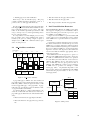
1
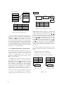
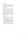
instruction set used in the classic MIPS R4000.
Some 32-bit compatibility features are missing and floating point support is experimental.
Achievable clock speed is above 100MHz on the
Altera Stratix IV and average cycles per instruction is close to 1.2 when booting the FreeBSD
operating system. In summary, the high-level design and performance of BERI is comparable to
the MIPS R4000 design of 1991, though the design tends toward extensibility and clarity over
efficiency in the micro-architecture.
...
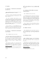
We developed device drivers for three Altera IP
cores: the JTAG UART (altera jtag uart), triplespeed MAC (atse), and SD Card (altera sdcard),
which implement low-level console/tty, Ethernet
interface, and block storage classes. In addition,
we have implemented a generic driver for Avalonattached devices (avgen), which allows memory
mapping of arbitrary bus-attached devices without interrupt sources, such as the DE4 LED block,
BERI configuration ROM, and DE4 fan and temperature control block.
Finally, we have developed a device driver for the
Terasic multitouch display (terasic mtl), which implements a memory-mapped pixel buffer, system
console interface for the text frame buffer, and
memory-mapped touchscreen input FIFO. Using
this driver, UNIX can present a terminal interface,
but applications can also overlay graphics and
accept touch input.
In addition to the drivers described above, made extensive
modifications to the exiting cfi(4) (Common Flash Interface) driver to fully support Intel NOR flash and improve
write performance.
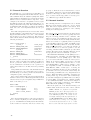
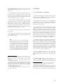
2.1. Flat Device Tree
Most aspects of BERI board configuration is described in
a Flat Device Trees (FDT) which are commonly used on
PowerPC and ARM-based systems [4]. Currently a Device
Tree Blob (DTB) is built into each FreeBSD kernel and
describes a specific hardware configuration. Each DTB is
built from a device tree syntax (DTS) file by the device tree
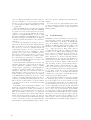
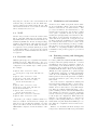
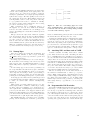
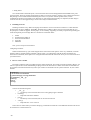
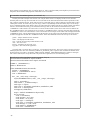
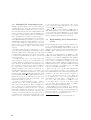
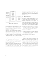
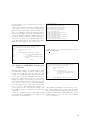
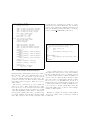
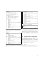
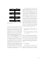
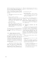
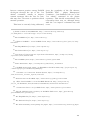
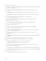
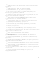
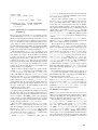
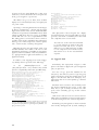
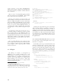
compiler2 before being embedded in the kernel. Figure 2
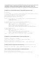
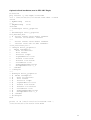
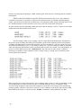
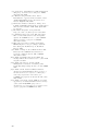
exerpts the DTS file boot/fdt/dts/beripad-de4.dts
and includes the BERI CPU, 1GB DRAM, programmable
interrupt controller (PIC), hardware serial port, JTAG UART,
SD card reader, flash partition table, gigabit Ethernet, and
touchscreen.
3. The early boot sequence
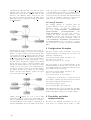
The common FreeBSD boot sequence begins with CPU
firmware arranging to run the FreeBSD boot2 second-stage
boot loader which in turn loads /boot/loader which loads
2 dtc(1)
180
model = " SRI / Cambridge B e r i P a d ( DE4 ) " ;
c o m p a t i b l e = " s r i −c a m b r i d g e , b e r i p a d −de4 " ;
cpus {
cpu@0 {
d e v i c e −t y p e = " cpu " ;
c o m p a t i b l e = " s r i −c a m b r i d g e , b e r i " ;
};
};
soc {
memory {
d e v i c e _ t y p e = " memory " ;
r e g = <0 x0 0 x40000000 > ;
};
b e r i p i c : beripic@7f804000 {
c o m p a t i b l e = " s r i −c a m b r i d g e , b e r i −p i c " ;
i n t e r r u p t −c o n t r o l l e r ;
r e g = <0 x 7 f 8 0 4 0 0 0 0 x400 0 x 7 f 8 0 6 0 0 0 0 x10
0 x 7 f 8 0 6 0 8 0 0 x10 0 x 7 f 8 0 6 1 0 0 0 x10 > ;
}
serial@7f002100 {
c o m p a t i b l e = " ns16550 " ;
r e g = <0 x 7 f 0 0 2 1 0 0 0 x20 > ;
};
serial@7f000000 {
c o m p a t i b l e = " a l t e r a , j t a g _ u a r t −11_0 " ;
r e g = <0 x 7 f 0 0 0 0 0 0 0 x40 > ;
};
sdcard@7f008000 {
compatible = " a l t e r a , sdcard_11_2011 " ;
r e g = <0 x 7 f 0 0 8 0 0 0 0 x400 > ;
};
flash@74000000 {
partition@20000 {
r e g = <0 x20000 0 xc00000 > ;
l a b e l = " fpga0 " ;
};
partition@1820000 {
r e g = <0 x1820000 0 x027c0000 > ;
l a b e l = " os " ;
};
};
ethernet@7f007000 {
compatible = " altera , atse ";
r e g = <0 x 7 f 0 0 7 0 0 0 0 x400 0 x 7 f 0 0 7 5 0 0 0 x8
0 x 7 f 0 0 7 5 2 0 0 x20 0 x 7 f 0 0 7 4 0 0 0 x8
0 x 7 f 0 0 7 4 2 0 0 x20 > ;
};
touchscreen@70400000 {
c o m p a t i b l e = " s r i −c a m b r i d g e , m t l " ;
r e g = <0 x70400000 0 x1000
0 x70000000 0 x177000 0 x70177000 0 x2000 > ;
};
};
Figure 2: Excerpt from Flat Device Tree (FDT) description of
the DE4-based BERI tablet.