1
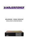
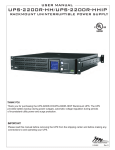
MajorCHARGE Power SYSTEM
®
INSTALLATION & OPERATION MANUAL
MAJORCHARGE DC System Manual / M601.4
Majorpower Corporation
7011 Industrial Drive
Mebane, NC 27302
Tel: 919.563.6610
Fax: 919.563.6620
Revision History
Product Manual #
Date
Release
M601.1
March 2008
Issue 1
M601.2
June 2008
Issue 2
M601.3
October 2008
Issue 3
M601.4
November 2009
Issue 4
Copyright Notice
©2009, Majorpower Corporation. All rights reserved. This document may not be
copied in whole or in part, or transferred to any other media, without the written
permission of Majorpower Corporation.
Printed in the United States of America.
®
®
Majorpower and MAJORCHARGE are registered trademarks.
Page 2
MAJORCHARGE DC System Manual / M601.4
Table of Contents
1. INTRODUCTION.......................................................................................... 4
2. IMPORTANT SAFETY INSTRUCTIONS ................................................. 4
SAFETY STATEMENT .......................................................................................... 4
SYMBOLS ........................................................................................................... 5
4. INSTALLATION ........................................................................................... 6
TOOLS REQUIRED .............................................................................................. 6
PRELIMINARY INSPECTION ................................................................................. 6
SYSTEM MOUNTING .......................................................................................... 6
SHELF INTERNAL WIRING .................................................................................. 6
AC INPUT CONNECTIONS .................................................................................. 6
DC LOAD/BATTERY CONNECTIONS ................................................................... 7
ALARM CONNECTIONS (OPTIONAL)................................................................. 8
TEMPERATURE PROBE CONNECTION (OPTIONAL) .......................................... 8
TEMPERATURE COMPENSATION THEORY ............................................................ 9
TEMPERATURE COEFFICIENT SETTING ................................................................ 9
FLOATING CHARGE VALUE CALCULATION .......................................................... 9
5. SYSTEM OPERATION ................................................................................ 9
CIRCUIT BREAKER CONTROLS ........................................................................... 9
FRONT PANEL INDICATORS ................................................................................ 9
CONTROLLER’S OPERATION ............................................................................ 10
CONTROLLER NAVIGATION .............................................................................. 10
DC DISTRIBUTION............................................................................................ 11
WARRANTY ..................................................................................................... 12
Page 3
MAJORCHARGE DC System Manual / M601.4
1. INTRODUCTION
Thank you for choosing MAJORPOWER as the power conversion products supplier to
your company. Our power conversion products are designed and built for full reliability
at multiple locations and variety of applications. These intelligent, dependable power
systems provide economical power support for all your network needs.
This manual contains information and technical details for all rack mounted models in
the MAJORCHARGE power system family. The general operation procedures are
common, however in some instances, all or part of the information will not apply to the
specific model purchased.
This user’s manual contains important technical instructions to be followed by
qualified personnel responsible for the installation, start-up and maintenance of
this unit. We recommend that this manual be read attentively to insure safe and
reliable operation of this equipment.
Should you require any assistance, please call our Application Engineering department
at:
Tel: 888-708-6610 or (919) 563-6610
Fax: 888-708-6620 or (919) 563-6620
Email: [email protected]
2. IMPORTANT SAFETY INSTRUCTIONS
Safety Statement
SAVE THESE INSTRUCTIONS - This manual contains important equipment
instructions that should be followed during installation and maintenance of the power
equipment.
To reduce the risk of electric shock, install the equipment in a temperature and
humidity controlled indoor environment, free of conductive contaminants. Ambient
o
o
temperature should not exceed 50 C (122 F).
¾
¾
¾
¾
The following precautions should be respected when working on power equipment:
Remove watches, rings, or other metal objects.
Use tools with insulated handles.
Wear rubber gloves and boots.
Page 4
MAJORCHARGE DC System Manual / M601.4
Additional Safety Notes
¾
Upon receipt, examine the shipment box for damage. Notify the carrier immediately,
before opening if damage is evident.
¾
Do not open or disassemble the equipment, warranty will be voided.
¾
Do not operate near water or in excessive humidity.
¾
Keep liquid and foreign objects from entering the equipment.
¾
Install the equipment in a well-ventilated area. Do not block front air vents, or rear air
exhausts of the unit.
¾
Do not operate the equipment close to combustible gas or open fire.
¾
The AC breaker must provide adequate isolation between the system input and
commercial AC main
¾
The system has passed stringent system testing prior to shipment. To avoid electrical
shock, the rectifier system requires a single ground point permanently connected to
earth ground
¾
Before installing the system, verify the AC input voltage and frequency, the AC breaker
rating and type, and other environmental conditions as noted in the specifications
¾
Do not operate the equipment if the unit is leaking any liquid or if a white powdery
residue is found to be present.
¾
Temperature: The equipment should be operated in an ambient temperature range of
0°C to +45°C or output efficiency may be affected. Air flow to the equipment must not
be impeded.
¾
Reduced air flow: Installation of the equipment in a rack should be such that the
amount of air flow required for safe operation of the equipment is not compromised.
¾
Mechanical loading: Mounting of the equipment in a rack should be level and
balanced.
¾
Wiring: Adequate input power must be supplied to the equipment for proper use;
correct wiring sizes must be respected.
¾
Grounding: Reliable grounding of rack-mounted equipment should be maintained.
Symbols
PROTECTIVE GROUNDING TERMINAL: A terminal, which must be
connected to earth ground prior to making any other connection to the
equipment.
This symbol indicates the word "phase".
Page 5
MAJORCHARGE DC System Manual / M601.4
4. INSTALLATION
Tools Required
The following tools are recommended for installation:
Phillips no.2 screwdriver
Insulated slotted screwdriver – blade size 1/4"
Insulated slotted screwdriver – blade size 1/8"
Insulated side cutters
Metric socket wrenches with extensions
Preliminary Inspection
Prior to removing the system from the carton, note any damage to the carton. Remove
the system from the packaging and inspect the shelf and components for any dents or
damage. If any damage is noted, contact the carrier immediately.
System Mounting
The MAJORCHARGE Power System is shipped in one carton and the rectifiers are
shipped separately in individual cartons. The system is shipped with the control unit
already installed. The system is designed for airflow from the front to the rear. The
front of the system should be clear of all obstruction to allow for proper ventilation,
proper access to the controller screen, installation, and maintenance.
A relay rack, provided by the customer, should meet EIA-310 standard rail spacing
dimensions for horizontal aperture 17.75 inch (450mm). At least 3U or 5.25 inch is
required for the chassis. The relay rack should be mounted to the superstructure and
floor per customer-provided engineering drawings. Mount the power system in the
rack with the appropriate screws for the rack application. Allow working room in the
rear/top of the system for making AC Mains and DC/Battery Load connections.
Shelf Internal Wiring
The shelf comes pre-wired and assembled, equipped with the controller and DC circuit
breaker modules. All internal connections are made at the factory; no internal shelf or
module wiring is required. Caution – Do not modify or disturb system wiring when
making AC and DC installation wire connections.
AC Input Connections
The power system is equipped with one AC Input terminal located on the rear of the
shelf. The power system is also provided with an integrated AC MAINS circuit breaker
rated for 40 amps. Typical installations are completed with customer supplied wire
meeting the 10AWG stranded wire suggested requirements. All AC connections
should be performed by a qualified electrician and be in compliance with the National
Electrical Code or prevailing authority codes for the installation.
The AC source wiring should be configured for One (1) circuit at 40 amp maximum
current draw by the power system with 208~240 VAC source. Typical installations
include L1-L2-G and some may include L-N-G. The High Line (HL) operations are
defined at an AC line input range of 185 VAC - 264 VAC. The Low Line (LL) operations
are defined at an AC line input range of 100 VAC – 185 VAC.
Page 6
MAJORCHARGE DC System Manual / M601.4
Warning: The system operates at AC voltages that can produce fatal electrical shock.
Installation and maintenance personnel must observe all safety precautions.
Warning: Confirm the operating voltage and proper grounding of the incoming line
before proceeding.
1.
2.
3.
4.
5.
6.
7.
Remove the AC protection cover plate.
Loosen the input terminal screws.
Strip 10mm of wire insulation from the end of each wire and insert into the
terminal block. Secure each wire and install AC protection cover plate.
Insert rectifiers into available slots and press firmly to ensure they are
seated. Tighten the retaining screws on the top and bottom of each
rectifier module.
Switch the AC Mains input breaker to the ON position. The rectifiers will
start in 3-5 seconds. (soft start)
Press the white on/off button on the controller to check system parameters.
Turn off the controller and the AC mains breaker before proceeding to the
DC load and Battery connections installation.
DC Load/Battery Connections
Caution: Basic system functional testing should be completed prior to the load or
battery connections being applied.
Warning: Ensure the AC circuit breaker and the power switch of the controller is in the
“Off” position when inserting the rectifiers and controller unit.
The integrated circuit breakers are shipped in the OFF position.
breaker is off before making DC load connections.
Ensure the load
1. Strip 10mm of wire insulation and connect the positive load cable to the positive
terminal block of the system.
2. Strip 10mm of wire insulation and connect the negative load cable to the negative
terminal block of the system.
After the DC load cables have been attached, turn the equipment on and check the
operational parameters of the power system and load equipment.
Page 7
MAJORCHARGE DC System Manual / M601.4
The Controller is shipped in the OFF position. Ensure the on/off switch is outward
(OFF) before making battery connections. Use a volt meter to check the polarity
and voltage of the system before making battery connections. Equipment could
be damaged if connections are not correct.
3. Connect the positive battery cable to the positive terminal.
4. Connect the negative battery cable to the negative terminal.
5. Engage the battery circuit breaker.
(NOTE: 130V Systems)
The circuit breakers provided in 130VDC systems are two (2) pole and therefore will
open or close both the positive and negative connections at the same time. Many
130 volt systems effectively float with respect to earth ground. There is no common
return bus in a 130 volt system. Match the polarity of the battery to the markings on
the circuit breaker.
Alarm Connections (optional installation)
The shelf alarm block is located on the back panel. These dry contacts allow
customer provided alarm systems to be connected to the power system. Alarms that
are triggered in the controller will appear on the Form-C terminal block.
After programming parameters, always return the control screen to the main menu
view (ESC) for proper indications on the contacts.
Terminal Pins
Status
Alarm
1&2
3&4
Normal Close
Normal Close
AC Input Voltage Fault
DC Output Voltage Fault
5&6
7&8
Normal Close
Normal Close
Rectifier Faults
DC LOAD Breaker
Relay Rating
60W; 2A @ 30VDC
max 220VDC
1&2) AC Voltage Fault
- AC input source voltage is missing or measured to be out of the parameter trigger
range; either high or low.
- SPD fault indication (wall mounted configurations, if equipped)
3&4) DC Output Voltage Fault
- DC BATTery Breaker - Sensor circuit indicates the breaker position - open/closed.
- DC System Voltage High or Low
5&6) Rectifier Faults
- Module Failure, Fan Fail, Internal High-Temp, Auto-protection Shutdown modes
7&8) DC LOAD Breaker
- Sensor circuit indicates the breaker position - open/closed
Temperature Probe Connection
(optional installation)
The temperature compensation probe should be connected to the back of the shelf
using the supplied connector and cable assembly. Take care not to pinch or crimp
the wire assembly when securing it to the installation raceways etc. The square probe
should be connected on or near the central part of the battery being charged by the
Page 8
MAJORCHARGE DC System Manual / M601.4
power system. Temperature changes measured by the probe will be used by the
controller to facilitate the voltage compensation feature in the system. For example,
if the temperature increases, the voltage will decrease therefore helping to prevent
excessive heating in the battery.
Temperature compensation theory
When the temperature probe is connected to the system, the controller will perform
voltage control based on temperature. The probe should be installed on or near the
battery for best results and accurate temperature compensation. Each system ships
with the probe pre-assembled on a 10M (~32ft) cable. Secure the cable during
installation taking care not to crimp or pinch the wire.
Temperature coefficient setting
Obtain the temperature coefficient in mV/°C for floating charge from the battery
supplier or input operation parameters manually. Input the coefficient value in mV/°C
and reference temperature in °C for the battery parameters under the controller menu.
Floating charge value calculation
When the battery temperature or system temperature is higher than the reference
(normally 25°C) the float charge voltage should be decreased. The float charge
voltage @ system temperature = Float charge voltage @ reference temperature +
temperature coefficient *(system temperature - reference temperature)
For example, if the temperature coefficient is set 50mV/°C and the reference
temperature is 25 °C, and the then the Float charge voltage@ reference temperature
is 53.8V, then the adjusted float charge voltage @ 45°C system temperature will be
52.8V.
5. SYSTEM OPERATION
Circuit Breaker Controls
(24V and 48V systems)
The system is equipped with TWO integrated circuit breakers for output protection.
One is for battery protection and the other is for DC load protection. These breakers
are located on the front of the system and marked LOAD and BATT.
(130V systems)
The system is equipped with ONE integrated circuit breaker for output load protection.
The two pole breaker is located on the front of the system and marked LOAD.
Supplemental battery over-current fault protection should be considered, as a part of
the battery system installation and based on the local installation requirements.
(ALL systems)
The supplemental AC Mains supply circuit breaker is located on the rear of the system
as additional protection for the input AC. This is not a replacement for the service
panel breaker installed per local codes for AC wiring.
Front Panel Indicators
Rectifier:
There are three LED lights on the each rectifier front panel.
Page 9
MAJORCHARGE DC System Manual / M601.4
“AC On” ---- LED on when AC input voltage of the rectifier is OK.
“Fault”--- LED lit when the rectifier is in a fault condition.
“STBY”--- LED on when the rectifier is powered off by the controller.
Controller:
There are two LEDs and the on/off switch in addition to the LCD screen and six
navigation/selection buttons.
“SYS” --- will be either green or amber indicating either Float or Equalize.
“ALM” --- red indicating alarm condition
Controller’s Operation
Functions and features
¾ Electric parameters detection and measurement:
AC input voltage, DC output voltage, rectifiers output current, charge and discharge
current of battery units, temperature of battery units.
¾ System failures detection
Problems and failures can be detected from: AC input, DC input, output current
limitation of rectifiers, over temperature of rectifiers, cooling fans, lightning protection
and surging protection, battery capacity, melt fuse of battery units and distribution.
¾ Electric parameters Control
MCR24/40; Range of DC output voltage:
MCR48/25; Range of DC output voltage:
MCR130/10; Range of DC output voltage:
21.5V-28.8V
43.0V-57.8V
98.0V-157.0V
¾ Battery management
Floating & Equalize voltage setting
Battery charge mode selection:Equalizing charge mode with limited current, thermal
compensation for floating charge, accumulative number indication of ampere-hours of
battery discharge.
Battery Low Voltage Disconnect (LVD) protection (if option is factory installed)
- System product codes include “L” in position nine – i.e. MCS48/100LX-3U
Controller Navigation
Caution: The power of the controller MUST be in “Off” position when inserting the
controller into the housing and the system is powered on.
After powered on, the Main Status Menu automatically appears:
System:
OK!
AC vol:
218 V
DC vol:
00.0 V
DC cur:
00.0 A
If everything is OK, then the first line shows “System OK”. The next three lines show
the AC voltage, system output DC voltage and sum current of all the working rectifiers.
If an alarm is present the System line will show the failure information. Each problem
is displayed at 2-second interval in turn if there is more than one problem.
Page 10
MAJORCHARGE DC System Manual / M601.4
Four kinds of problem information can be displayed:
¾ DC Output Failure --- tripped circuit breaker.
¾ Battery Failure --- battery disconnected or battery circuit breaker tripped or
battery low voltage--- low battery capacity
¾ Rectifier Failure --- failures include AC Input, DC Output, module over-voltage,
high temp, current limit, low current output, fan fail.
¾ AC Input Failure ---AC Mains input is in over-voltage or under-voltage.
Press Key Pad functions under the Main Status Menu:
F&E
Manually change between equalizing and floating charge.
Equalizing Æ Floating, or Floating Æ Equalizing.
SEL
circular display “Battery Inquiry”or“System Setting”menu.
RTN or ESC
Refresh new screen. Used to resume the normal display when display is in sleep
mode or return to Home page.
ARROWS
Navigation within the screens and change parameter values up or down..
Press SEL key to enter system settings menu and view current system status
parameters.
Press RTN key to activate a menu for parameter changes. Note the pointer will
appear to the right of the parameter to be changed. Make adjustments in the value
using the up and down arrows. Save changes by pressing the RTN key.
When the selection pointer appears, use the SEL key to move the selector among
different parameters on the same page.
Press UP to increase the values. Press DOWN to decrease the values.
Press ESC and the set values are not stored. The system will return to the previous
menu and the pointer will disappear.
Controller Display Contrast
Press and hold the “up” arrow for 3~5 seconds to increase contrast.
Press and hold the “down” arrow for 3~5 seconds to decrease contrast.
Press and hold the “esc” key for 3~5 seconds to backlight operation.
DC distribution
System Voltage
24V
48V
130V
Load Circuit
125 amp
125 amp
50 amp
Battery Circuit
125 amp
125 amp
not equipped
Page 11
Switched Pole
Single
Single
Double
MAJORCHARGE DC System Manual / M601.4
Notes:
Model Number:
Serial Number:
Installation Date:
Warranty
This product is warranted against defect in materials and workmanship for a period of
two (2) years from date of shipment. During warranty period, Majorpower
Corporation will, at its option, either repair or replace products that prove to be
defective.
Limitation of Warranty
The foregoing warranty shall not apply to defects resulting from unauthorized
modification, misuse, improper installation, or operations beyond those described in
this manual. No other warranty is expressed or implied.
Every care has been taken in compiling the information in this publication; Majorpower
cannot accept legal liability for any inaccuracies contained herein. Majorpower
Corporation reserves the right to alter specifications without notice and whenever
necessary to ensure optimum performance from its product range.
Majorpower Corporation is not responsible for any lost profits or revenue, loss of use
software, loss of data, cost of substitute software, claims by third parties, or for other
similar costs. In no case shall Majorpower Corporation’s liability exceed the amount
of the license fee.
Page 12