1
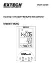
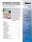
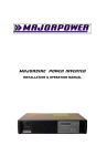
Circuit breaker panel
INSTALLATION & OPERATION MANUAL
MAJORCHARGE DC Distribution Manual / M701.1
Majorpower Corporation
7011 Industrial Drive
Mebane, NC 27302
Tel: 919.563.6610
Fax: 919.563.6620
Revision History
Product Manual #
M701.1
Date
Release
October 2008
Issue 1
Copyright Notice
©2008, Majorpower Corporation. All rights reserved. This document may not be
copied in whole or in part, or transferred to any other media, without the written
permission of Majorpower Corporation.
Printed in the United States of America.
®
®
Majorpower and MAJORCHARGE are registered trademarks.
Page 2
MAJORCHARGE DC Distribution Manual / M701.1
Notes:
Model Number:
Serial Number:
Installation Date:
This user’s manual contains important technical instructions to be
followed by qualified personnel responsible for the installation,
start-up and maintenance of this equipment. It is recommended
that this manual be read attentively to insure safe and reliable
operation of this equipment.
Warranty
This product is warranted against defect in materials and workmanship for a period of
one year from date of shipment. During warranty period, Majorpower Corporation
will, at its option, either repair or replace products that prove to be defective.
Limitation of Warranty
The foregoing warranty shall not apply to defects resulting from unauthorized
modification, misuse, improper installation, or operations beyond those described in
this manual. No other warranty is expressed or implied.
Every care has been taken in compiling the information in this publication; Majorpower
cannot accept legal liability for any inaccuracies contained herein. Majorpower
Corporation reserves the right to alter specifications without notice and whenever
necessary to ensure optimum performance from its product range.
Majorpower Corporation is not responsible for any lost profits or revenue, loss of use
software, loss of data, cost of substitute software, claims by third parties, or for other
similar costs. In no case shall Majorpower Corporation’s liability exceed the amount
of the license fee.
Page 3
MAJORCHARGE DC Distribution Manual / M701.1
Table of Contents
WARRANTY ....................................................................................................... 3
1. INTRODUCTION.......................................................................................... 5
2. IMPORTANT SAFETY INSTRUCTIONS ................................................. 6
SAFETY STATEMENT .......................................................................................... 6
3. OVERVIEW................................................................................................... 7
SYSTEM CONFIGURATIONS ................................................................................ 7
4. INSTALLATION ........................................................................................... 8
WARNING .......................................................................................................... 8
TOOLS REQUIRED .............................................................................................. 8
PRELIMINARY INSPECTION ................................................................................. 8
PANEL MOUNTING ............................................................................................. 8
CONNECTIONS – CHASSIS GROUND ................................................................... 8
CONNECTIONS - INPUT....................................................................................... 8
CONNECTIONS - OUTPUT ................................................................................... 9
CONNECTIONS - ALARMS................................................................................... 9
5. SYSTEM OPERATION ................................................................................ 9
FINAL INSPECTION ............................................................................................. 9
Page 4
MAJORCHARGE DC Distribution Manual / M701.1
1. INTRODUCTION
Thank you for choosing MAJORPOWER as the power conversion
products supplier to your company. Our power conversion products
are designed and built for full reliability at multiple locations and
variety of applications. These intelligent, dependable power systems
provide economical power support for all your network needs.
This manual contains information and technical details for DC
distribution models in the MAJORCHARGE power system family.
The general operation procedures are common, however in some
instances, all or part of the information will not apply to the specific
model purchased.
This user’s manual contains important technical instructions to
be followed by qualified personnel responsible for the
installation, start-up and maintenance of this equipment. We
recommend that this manual be read attentively to insure safe
and reliable operation of this equipment.
Should you require any assistance, please call our Application
Engineering department at:
Tel: 888-708-6610 or (919) 563-6610
Fax: 888-708-6620 or (919) 563-6620
Email: [email protected]
Page 5
MAJORCHARGE DC Distribution Manual / M701.1
2. IMPORTANT SAFETY INSTRUCTIONS
Safety Statement
SAVE THESE INSTRUCTIONS - This manual contains important
equipment instructions that should be followed during installation and
maintenance of the power equipment.
To reduce the risk of electric shock, install the equipment in a
temperature and humidity controlled indoor environment, free of
conductive contaminants. Ambient temperature should not exceed
50oC (122oF).
¾
¾
¾
¾
The following precautions should be respected when working on
power equipment:
Remove watches, rings, or other metal objects.
Use tools with insulated handles.
Wear rubber gloves and boots.
Additional Safety Notes
¾
Upon receipt, examine the shipment box for damage. Notify the
carrier immediately, before opening if damage is evident.
¾
Do not open or disassemble the equipment, warranty will be voided.
¾
Do not operate near water or in excessive humidity.
¾
Keep liquid and foreign objects from entering the equipment.
¾
Install the equipment in a well-ventilated area.
¾
Do not operate the equipment close to combustible gas or open fire.
¾
Reduced air flow: Installation of the equipment in a rack should be
such that the amount of air flow required for safe operation of the
equipment is not compromised.
¾
Mechanical loading: Mounting of the equipment in a rack should be
level and balanced.
¾
Wiring: Adequate input power must be supplied to the equipment for
proper use; correct wiring sizes must be respected.
¾
Grounding: Reliable grounding of rack-mounted equipment should
be maintained.
Page 6
MAJORCHARGE DC Distribution Manual / M701.1
3. OVERVIEW
System Configurations
The power distribution panel is rated for 100 amps per bus. Each bus can be
equipped with circuit breakers rated from 1 amp to 30 amp rating per position.
Multiple configurations have been created for a variety of applications. The plug-in
circuit breakers can be easily installed / removed / arranged in the field because of the
removable faceplate design and integrated backplane.
MCB 8/0-1U
MCB 6/6-1U
Page 7
MAJORCHARGE DC Distribution Manual / M701.1
4. INSTALLATION
Warning
All connections should be performed by qualified service personnel and be in
compliance with the latest release of the National Electrical Code or prevailing
authority codes for the installation. This panel should be installed in a restricted area.
Tools Required
The following tools are recommended for installation:
Phillips no.2 screwdriver
Insulated slotted screwdriver – blade size 1/8"
Insulated side cutters
Multimeter
Wire and cable ties
Compression terminal and crimper
Preliminary Inspection
Prior to installation the equipment, take a few moments to familiarize yourself with the
parts of the panel. Ensure that the equipment has not sustained damage during
shipping.
Panel Mounting
Mount the panel is a standard 19 inch rack using the provided #12-24 x ½” screws.
Four screws are provided with each panel. Ensure the panel is not mounted in a
method that creates a potentially hazardous condition for users or equipment.
Connections – Chassis Ground
The panel chassis is designed for connection to the grounding network of the site
installation. Connect suitable wire and crimp terminal to the panel using the supplied
studs and locking nuts. Torque fasteners to 24 in-lbs. Bond the other end of the wire to
the location installation per local ground network requirements.
Recommended Lug: Panduit LCD6-14AF
6AWG; ¼” stud; 5/8” hole space; width .625”
Connections - Input
The panel is designed to a maximum amperage rating of 100 A per bus when properly
installed using 2 AWG wire and an upstream (supply) overcurrent device of not more
than 125 amps. All wiring used with this product should be rated for 90°C or greater. If
alternate installation designs are used, the wire and overcurrent device must be
selected based on the prevailing authority codes for the installation. Input connections
require the 90 degree compression lug for proper installation.
Recommended Lug: Panduit LCD2-14AF-Q
2AWG; ¼” stud; 5/8” hole space; width .625”; 90 degree terminal
1.
2.
Attach the lug to the wire and crimp according to manufacturer’s instructions.
Use appropriate shrink insulation over the un-insulated terminal barrels.
Remove the safety covers from the panel by pulling straight out from the back of
the panel.
Page 8
MAJORCHARGE DC Distribution Manual / M701.1
3.
4.
Using the supplied lock nuts, position the lug on the terminal studs and tighten to
24 in-lbs.
Confirm that the appropriate battery and return wires are attached to the proper
connections for the system installation.
Power Verification
Test the polarity of the panel prior to connection of loads. Turn on the supply
overcurrent device for the bus being installed.
6. Verify the polarity and voltage is correct at the input terminal using a multimeter.
7. Check the front panel status light. PWR - Green or Red. Any installed circuit
breaker in the off position will create a red LED.
8. Verify the Form-C alarm terminal connectivity based on the alarm or non-alarm
conditions. Use the multimeter to check continuity of the alarm terminal pins
while cycling the circuit breakers that are installed in the panel.
9. After testing, power OFF the supply overcurrent device.
10. Install the input terminal safety covers and secure the appropriate strain reliefs
for the wires.
5.
Repeat these steps for each bus being installed.
Connections - Output
The panel is designed to support specific circuit breakers. Use only approved circuit
breakers supplied with this panel. Use the output terminals to supply load connections
by attaching #10-22 AWG wire/terminals for each piece of equipment.
1.
2.
3.
Attach the equipment battery and return wires to the corresponding circuit
breaker position. Torque screw to 9 in-lbs.
Label the panel circuit card for each position installed and used.
Install the correct circuit breaker into the corresponding circuit position.
Repeat these steps for each load circuit.
Connections - Alarms
The alarm terminal accepts #12-26 AWG wire. Strip the end of the wire and insert
into the positions used for the local alarm network.
5. SYSTEM OPERATION
Final Inspection
Check all connection and installation for accuracy.
installation debris from area.
Secure all wires and clear any
Energize the supply overcurrent device then energize each load equipment circuit
breaker as required.
Page 9