1
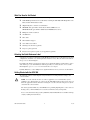
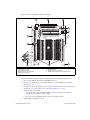
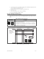
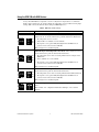
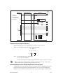
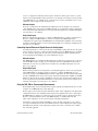
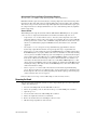
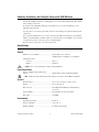
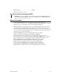
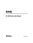
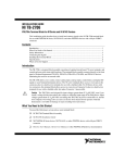
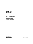
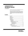
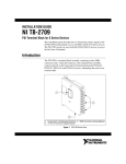
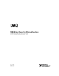
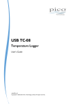
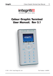
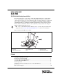
INSTALLATION GUIDE
SCB-100
100-Pin Shielded Desktop Connector Block
This guide describes how to connect and use the NI SCB-100 with 100-pin data acquisition (DAQ)
devices. The SCB-100 is a shielded desktop accessory with 100 screw terminals, a cold-junction
compensation temperature sensor for use with thermocouples, and a strain-relief bar for securing signal
wires or cables. The SCB-100 connects to E Series MIO devices (NI 6025E, NI 6031E, NI 6033E,
and NI 6071E), DIO devices (PCI-DIO-96, NI 6508, NI 6509, NI 6511, NI 6512, NI 6513, NI 6514,
NI 6515, NI 6527, and NI 6528), TIO Series devices (NI 6624), or other products with a 100-pin
0.050 series shielded D-type I/O connector.
Note To use the SCB-100 with a DIO or TIO Series device, you must change the default switch
setting. Refer to the Using the SCB-100 with DIO/TIO Devices section for more information.
Figure 1 shows the SCB-100 connector block.
1
2
3
8
9
4
5
7
6
1
2
3
Quick Reference Label
Top Cover
100-Pin Connector Screw
4
5
6
Grounding Screw
100-Pin I/O Connector
Base
7
8
9
Strain-Relief Hardware
Strain-Relief Screws
SCB-100 Board Assembly
Figure 1. SCB-100 Connector Block
Contents
What You Need to Get Started ............................................................................................................ 2
Attaching the Quick Reference Label.................................................................................................. 2
Getting Started with the SCB-100 ....................................................................................................... 2
Using the SCB-100 with DIO/TIO Devices ........................................................................................ 4
Using the SCB-100 with MIO Devices ............................................................................................... 5
Removing the Board ............................................................................................................................ 8
Soldering, Desoldering, and Cutting Via Traces on the SCB-100 Board............................................ 9
Specifications....................................................................................................................................... 9
Where to Go for Support ..................................................................................................................... 10
What You Need to Get Started
To set up and use your SCB-100, you need the following:
❑ SCB-100 100-pin shielded connector block kit, containing the SCB-100, SCB-100 quick reference
label, and SCB-100 Installation Guide
❑ 100-pin DAQ device and device documentation
❑ SH100100 cable (part number 182853-0x) for E Series/MIO devices or
SH100-100-F cable (part number 185095-0x) for DIO/TIO Series devices
❑ Phillips #1 and #2 screwdrivers
❑ ≤26 AWG wire
❑ Wire cutters
❑ Wire insulation strippers
❑ 1/8 in. flathead screwdriver
❑ Soldering iron and solder (optional)
❑ Long nose pliers (optional)
❑ Resistors and capacitors specific to your application (optional)
Attaching the Quick Reference Label
A quick reference label is included in the SCB-100 100-pin shielded connector block kit to show switch
configurations and define screw terminal pinouts for E Series devices. Place the label on the inside of
the top cover, as shown in Figure 1.
For a PDF of the E Series quick reference label, refer to the KnowledgeBase document, Where Can I
Find .PDF Copies of the SCB-100 and/or SCB-68 Quick Reference Label Stickers?. To access this
KnowledgeBase, go to ni.com/info and enter the info code rdwpdf.
For DIO, TIO Series, or other 100-pin device signal information, refer to your device documentation.
Getting Started with the SCB-100
The following cautions contain important safety information concerning hazardous voltages and
connector blocks.
Caution To avoid electrical shock, do not remove equipment covers or shields unless you are
qualified to do so. If signal wires are connected to the SCB-100, hazardous voltages may exist even
when the equipment is turned off. Before removing the cover, disconnect the AC power or any live
circuit from the connector block.
The chassis ground terminals on your SCB-100 are for grounding high-impedance sources such as a
floating source (1 mA maximum). Do not use these terminals as safety earth grounds.
Do not connect hazardous voltages (≥42 Vpk/60 VDC). National Instruments is not liable for damage
or injury resulting from such misuse.
SCB-100 Installation Guide
2
ni.com
Figure 2 shows the SCB-100 board parts locator diagram.
2
1
3
3
4
5
6
6
9
6
8
1
2
3
4
5
3
7
Switches S4, S5, and S6
100-Pin I/O Connector
Board Mount Screw Hole
Signal Accessory Power LED (DS1)
Switches S1, S2, and S3
6
7
8
9
3
Screw Terminals
Breadboard Area
Vias Shorted to Screw Terminal
Cold-Junction Compensation Temperature Sensor
Figure 2. SCB-100 Board Parts Locator Diagram
To get started with the SCB-100, complete the following steps while referring to Figures 1 and 2.
1.
Disconnect the 100-pin cable from the SCB-100, if connected.
2.
Remove the grounding screws on either side of the top cover with a Phillips #1 screwdriver.
Open the top cover.
3.
Configure switches for the signal types you are using, as explained in the Using the SCB-100 with
DIO/TIO Devices section or the Using the SCB-100 with MIO Devices section.
4.
5.
Adjust the strain-relief hardware.
a.
Loosen the strain-relief screws with a Phillips #2 screwdriver and slide the signal wires
through the front panel strain-relief opening.
b.
If you are connecting multiple signals, remove the top strain-relief bar.
Add insulation or padding if necessary.
© National Instruments Corporation
3
SCB-100 Installation Guide
6.
Connect the wires to the screw terminals by stripping 1/4 in. of insulation, inserting the wires into
the screw terminals, and tightening the screws.
7.
Reinstall strain-relief (if removed) and tighten the strain-relief screws.
8.
Close the top cover.
9.
Reinsert the grounding screws to ensure proper shielding.
10. Connect the SCB-100 to the 100-pin connector.
Using the SCB-100 with DIO/TIO Devices
DIO devices, TIO Series devices, and DAQ devices without analog input functionality must use the
DIO/passthrough mode. Move the switches to the DIO/passthrough mode switch setting as shown in
Table 1.
Table 1. DIO/TIO Series Device Switch Setting
Switch Setting
Description
S1
DIO/passthrough mode—Move switches S1, S2, S3, S4, S5, and S6 to the
positions shown at left. In this mode:
S2
•
All 100 signals from the DAQ device connect directly to screw terminals.
S3
•
The signal accessory power LED (DS1) does not light in this configuration.
S6 S5 S4
Refer to Figure 3 for a detailed diagram.
DAQ Device
SH100-100 Cable
Screw
Terminal
1
SCB-100
1
Refer to
Your Device
Documentation
for Device Signal
Information
2
2
99
99
100
100
NC
LED
NC
Temperature
Sensor
NC
S1
S2
S3
S6 S5 S4
Figure 3. DIO/Passthrough Mode Switch Setting
SCB-100 Installation Guide
4
ni.com
Using the SCB-100 with MIO Devices
You can take measurements with the SCB-100 and MIO DAQ devices, such as E Series, in a number
of ways. The SCB-100 has a temperature sensor for cold-junction compensation to accommodate
thermocouples. Switches S4, S5, and S6 configure the temperature sensor for different analog input
settings. Table 2 shows the different switch settings for MIO DAQ devices.
Table 2. MIO Device Switch Settings
Switch Setting
Description
MIO with disabled temperature sensor mode (default configuration)—Move
switches S1, S2, S3, S4, S5, and S6 to the positions shown at left. In this mode:
S1
•
The temperature sensor is not used.
S2
•
AI 0 and AI 8 are available on screw terminals.
S3
•
The signal accessory power LED (DS1) lights when the MIO device is
powered on and connected to the SCB-100.
S6 S5 S4
Refer to Figure 4 for a detailed diagram.
MIO with single-ended temperature sensor mode—Move switches S1, S2, S3,
S4, S5, and S6 to the positions shown at left. In this mode:
S1
•
The temperature sensor can be read using AI 0 in referenced single-ended
(RSE) mode.
•
AI 8 is available on a screw terminal.
•
The signal accessory power LED (DS1) lights when the MIO device is
powered on and connected to the SCB-100.
S2
S3
S6 S5 S4
Refer to Figure 4 for a detailed diagram.
S1
MIO with differential temperature sensor mode—Move switches S1, S2, S3,
S4, S5, and S6 to the positions shown at left. In this mode:
S2
•
The temperature sensor can be read using AI 0 and AI 8 in differential mode.
S3
•
The signal accessory power LED (DS1) lights when the MIO device is
powered on and connected to the SCB-100.
S6 S5 S4
Refer to Figure 4 for a detailed diagram.
S1
S2
S3
S6 S5 S4
© National Instruments Corporation
DIO/passthrough mode—You can use DIO/passthrough mode with an MIO
device.
Refer to Table 1 for configuration information and Figure 3 for a detailed
diagram.
5
SCB-100 Installation Guide
DAQ Device
+5 V
Refer to
Your Device
Documentation
for Device Signal
Information
SH100-100 Cable
Screw
Terminal
34
SCB-100
34
LED
AI 0
3
S5
4
S4
Temperature
Sensor
3
AI 8
4
Other
Pins
1
2
5
6
1
2
5
6
99
100
99
100
S1
S2
S3
S6
Figure 4. MIO Device Modes Switch Settings
Temperature Sensor Output and Accuracy
The SCB-100 temperature sensor outputs 10 mV/°C and has an accuracy of ±0.5 °C.
You also can determine the temperature using the following formulas:
TC = 100 × Vt
TK = TC + 273.15
9
T F = --- × T C + 32
5
where
Vt is the temperature sensor output voltage;
TK is the temperature in Kelvin;
TF and TC are the temperature readings in degrees Fahrenheit and degrees Celsius, respectively.
Note Use the average of a large number of samples to obtain the most accurate reading. Noisy
environments require averaging more samples for greater accuracy.
Connecting Nonreferenced or Floating Signal Sources to Analog Inputs
A floating signal source is a signal source that is not connected in any way to the building ground system
but has an isolated ground-reference point. If an instrument or device has an isolated output, that
instrument or device falls into the floating signal source category. Some examples of floating signal
SCB-100 Installation Guide
6
ni.com
sources are outputs for the following: thermocouples, transformers, battery-powered devices, optical
isolators, and isolation amplifiers. The ground reference of a floating source must be tied to the ground
of the MIO DAQ device to establish a local or onboard reference for the signal. If this reference is not
established, erratic readings from the board will occur.
Differential Inputs
To provide a return path for the instrumentation amplifier bias currents, floating sources must have
a 10 to 100 kΩ resistor connected to the AI GND signal line on one input if DC-coupled, or both inputs
if AC-coupled. For detailed information on connections to floating signal sources and differential inputs,
refer to the E Series User Manual.
Single-Ended Inputs
When measuring floating signal sources, configure the MIO DAQ device to supply a ground reference.
Therefore, configure the MIO DAQ device for referenced single-ended (RSE) input. In this
configuration, the negative input of the MIO DAQ device instrumentation amplifier is tied to the analog
ground. For detailed information on connections to floating signal sources and single-ended inputs, refer
to the E Series User Manual.
Connecting Ground-Referenced Signal Sources to Analog Inputs
A grounded signal source is connected in some way to the building system ground; therefore, the signal
source is already connected to a common ground point with respect to the MIO DAQ device (assuming
the host computer is plugged into the same power system). Nonisolated outputs of instruments and
devices that plug into the building power system fall into this category.
Differential Inputs
If the MIO DAQ device is configured for differential inputs, ground-referenced signal sources connected
to the SCB-100 board do not require special components added to the SCB-100 board. For detailed
information on connections to ground-referenced signal sources and differential inputs, refer to the
E Series User Manual.
Single-Ended Inputs
When measuring ground-referenced signals, the external signal supplies its own reference ground point,
and the MIO DAQ device should not supply one. Therefore, configure the MIO DAQ device for
nonreferenced, single-ended (NRSE) input mode. In this configuration, all of the signal grounds should
be tied to AI SENSE, which connects to the negative input of the instrumentation amplifier on the MIO
DAQ device. Referencing the signal to AI GND can cause inaccurate measurements resulting from an
incorrect ground reference. For detailed information on connections to ground-referenced signal sources
and single-ended inputs, refer to the E Series User Manual.
Using the SCB-100 for Thermocouple Measurements
The maximum voltage level generated by thermocouples is typically a few millivolts. Therefore, for best
resolution, use an MIO DAQ device with a high gain.
Thermocouples can be measured in either differential or single-ended configurations. The differential
configuration has better noise immunity, but the single-ended configuration has twice as many inputs.
The MIO DAQ device must have a ground reference because thermocouples are floating signal sources.
Therefore, you must install bias resistors if the MIO DAQ device is in differential mode. For
single-ended configuration, use the referenced single-ended input configuration.
Cold-junction compensation with the SCB-100 is accurate only if the temperature sensor reading is
close to the actual temperature of the screw terminals. Therefore, when reading thermocouples, keep the
SCB-100 away from drafts or other temperature gradients such as those caused by heaters, radiators,
fans, and warm equipment.
© National Instruments Corporation
7
SCB-100 Installation Guide
Optional Input Filtering and Broken Thermocouple Detection
To reduce noise, you can build a simple RC lowpass filter in the breadboard area.
Build broken-thermocouple-detection circuitry by connecting a high-value resistor between the positive
input and +5 V. The value of this resistor is relatively unimportant; a few megaohms or more works fine.
You can detect an open or defective thermocouple with a high-value resistor. If the thermocouple opens,
the voltage measured across the input terminals rises to +5 V, a value much larger than any legitimate
thermocouple voltage.
Sources of Error
When making thermocouple measurements with the SCB-100 and a MIO DAQ device, the possible
sources of error are compensation, linearization, measurement, and thermocouple wire errors.
•
Compensation error can arise from two sources—inaccuracy of the temperature sensor and
temperature differences between the sensor and the screw terminals. The sensor on the SCB-100
board is specified to be accurate to ±0.5 °C. Minimize temperature differences between the sensor
and the screw terminals by keeping the SCB-100 board away from drafts, heaters, and warm
equipment.
•
Linearization error is a consequence of the polynomials being approximations of the true
thermocouple output. The linearization error depends upon the degree of polynomial used.
•
Measurement error is the result of inaccuracies in the MIO DAQ device, including gain and offset.
If the MIO DAQ device is properly calibrated, the offset error should be zero. The only remaining
error is a gain error of ±0.08% of full range (refer to the DAQ device specifications). If the input
range is ±10 V and the gain is 500, gain error contributes 0.0008 by 20 mV, or 16 μV of error. If
the Seebeck coefficient of a thermocouple is 32 μV/°C, this measurement error adds 0.5 °C of
uncertainty to the measurement. For best results, use a well-calibrated MIO DAQ device so that
offsets can be ignored. Eliminate offset error by grounding one channel on the SCB-100 board and
measuring the voltage. This value, the offset of the MIO DAQ device, then can be subtracted by
software from all other readings.
•
Thermocouple wire error is the result of inconsistencies in the thermocouple manufacturing
process. These inconsistencies, or nonhomogeneities, are the result of defects or impurities in the
thermocouple wire. The errors vary widely depending on the thermocouple type and even the gauge
of wire used, but a value of ±2 °C is typical.
For best results, use an average of at least 100 readings to reduce the effects of noise.
Removing the Board
You can remove the board from the enclosure to solder components into place. To remove the board,
complete the following steps.
1.
Disconnect the 100-pin cable from the SCB-100, if connected.
2.
Remove the grounding screws on either side of the top cover with a Phillips #1 screwdriver.
3.
Open the top cover.
4.
Loosen the strain-relief screws with a Phillips #2 screwdriver.
5.
Remove the signal wires from the screw terminals.
6.
Remove the board mount screws and 100-pin connector screws.
7.
Tilt the board up and pull it out of the enclosure.
SCB-100 Installation Guide
8
ni.com
Soldering, Desoldering, and Cutting Via Traces on the SCB-100 Board
The applications discussed here require you to make modifications to the printed circuit board, usually
in the form of adding components or cutting jumpers. Use a low-wattage soldering iron (20 to 30 W)
when soldering to the board.
To desolder on the SCB-100, vacuum-type tools work best. Use care when desoldering to avoid
damaging component pads.
Use only rosin-core, electronic-grade solder. Acid-core solder damages the printed circuit board and
components.
For each screw terminal, there are one or two vias next to the silkscreen showing the screw terminal
number, as shown in Figure 2, number 8. The vias are shorted to the screw terminal so you can solder
a component to the via to connect it to the screw terminal signal.
The trace between each pair of vias can be cut if needed.
Specifications
Specifications listed below are typical at 25 °C unless otherwise noted.
General
Number of screw terminals....................................101 (includes one no connect);
all I/O signals are available at screw terminals
Cold-junction sensor
Accuracy ........................................................±0.5 °C
Output ............................................................10 mV/°C
Caution
Do not connect hazardous voltages (≥42 Vpk/60 VDC).
Power Requirement
Power consumption (at +5 VDC ±5%),
typical.....................................................................10 mA with no signal conditioning installed
Note
Limit the current drawn from the host computer’s +5 VDC to about 800 mA, maximum.
Physical
Box dimensions......................................................19.6 × 15.2 × 4.6 cm (7.7 × 6.0 × 1.8 in.)
Weight ....................................................................897 g (1 lb 15.6 oz)
I/O connectors........................................................One 100-pin male 0.050 series shielded D-type
connector
Screw terminals......................................................101, including one No Connect (NC)
Wire gauge .............................................................≤26 AWG
Environmental
Operating temperature ...........................................0 to 70 °C
Storage temperature ...............................................–55 to 125 °C
Relative humidity...................................................5 to 90% noncondensing
© National Instruments Corporation
9
SCB-100 Installation Guide
Maximum altitude..................................................2,000 m
Pollution Degree (indoor use only)........................2
Waste Electrical and Electronic Equipment (WEEE)
EU Customers At the end of their life cycle, all products must be sent to a WEEE recycling center.
For more information about WEEE recycling centers and National Instruments WEEE initiatives,
visit ni.com/environment/weee.htm.
Where to Go for Support
The National Instruments Web site is your complete resource for technical support. At
ni.com/support you have access to everything from troubleshooting and application development
self-help resources to email and phone assistance from NI Application Engineers.
National Instruments corporate headquarters is located at 11500 North Mopac Expressway, Austin,
Texas, 78759-3504. National Instruments also has offices located around the world to help address
your support needs. For telephone support in the United States, create your service request at ni.com/
support and follow the calling instructions or dial 512 795 8248. For telephone support outside the
United States, contact your local branch office:
Australia 1800 300 800, Austria 43 662 457990-0, Belgium 32 (0) 2 757 0020,
Brazil 55 11 3262 3599, Canada 800 433 3488, China 86 21 5050 9800,
Czech Republic 420 224 235 774, Denmark 45 45 76 26 00, Finland 385 (0) 9 725 72511,
France 33 (0) 1 48 14 24 24, Germany 49 89 7413130, India 91 80 41190000, Israel 972 3 6393737,
Italy 39 02 413091, Japan 81 3 5472 2970, Korea 82 02 3451 3400, Lebanon 961 (0) 1 33 28 28,
Malaysia 1800 887710, Mexico 01 800 010 0793, Netherlands 31 (0) 348 433 466,
New Zealand 0800 553 322, Norway 47 (0) 66 90 76 60, Poland 48 22 3390150,
Portugal 351 210 311 210, Russia 7 495 783 6851, Singapore 1800 226 5886,
Slovenia 386 3 425 42 00, South Africa 27 0 11 805 8197, Spain 34 91 640 0085,
Sweden 46 (0) 8 587 895 00, Switzerland 41 56 2005151, Taiwan 886 02 2377 2222,
Thailand 662 278 6777, Turkey 90 212 279 3031, United Kingdom 44 (0) 1635 523545
SCB-100 Installation Guide
10
ni.com
National Instruments, NI, ni.com, and LabVIEW are trademarks of National Instruments Corporation.
Refer to the Terms of Use section on ni.com/legal for more information about National
Instruments trademarks. Other product and company names mentioned herein are trademarks or trade
names of their respective companies. For patents covering National Instruments products, refer to the
appropriate location: Help»Patents in your software, the patents.txt file on your CD, or
ni.com/patents.
© 1995–2007 National Instruments Corporation. All rights reserved.
371224B-01
Apr07