1
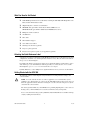
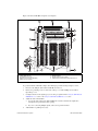
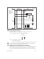
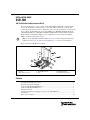
Figure 2 shows the SCB-100 board parts locator diagram.
2
1
3
3
4
5
6
6
9
6
8
1
2
3
4
5
3
7
Switches S4, S5, and S6
100-Pin I/O Connector
Board Mount Screw Hole
Signal Accessory Power LED (DS1)
Switches S1, S2, and S3
6
7
8
9
3
Screw Terminals
Breadboard Area
Vias Shorted to Screw Terminal
Cold-Junction Compensation Temperature Sensor
Figure 2. SCB-100 Board Parts Locator Diagram
To get started with the SCB-100, complete the following steps while referring to Figures 1 and 2.
1.
Disconnect the 100-pin cable from the SCB-100, if connected.
2.
Remove the grounding screws on either side of the top cover with a Phillips #1 screwdriver.
Open the top cover.
3.
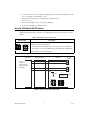
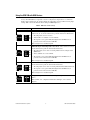
Configure switches for the signal types you are using, as explained in the Using the SCB-100 with
DIO/TIO Devices section or the Using the SCB-100 with MIO Devices section.
4.
5.
Adjust the strain-relief hardware.
a.
Loosen the strain-relief screws with a Phillips #2 screwdriver and slide the signal wires
through the front panel strain-relief opening.
b.
If you are connecting multiple signals, remove the top strain-relief bar.
Add insulation or padding if necessary.
© National Instruments Corporation
3
SCB-100 Installation Guide