1
Optional Input Filtering and Broken Thermocouple Detection
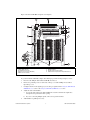
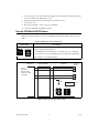
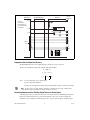
To reduce noise, you can build a simple RC lowpass filter in the breadboard area.
Build broken-thermocouple-detection circuitry by connecting a high-value resistor between the positive
input and +5 V. The value of this resistor is relatively unimportant; a few megaohms or more works fine.
You can detect an open or defective thermocouple with a high-value resistor. If the thermocouple opens,
the voltage measured across the input terminals rises to +5 V, a value much larger than any legitimate
thermocouple voltage.
Sources of Error
When making thermocouple measurements with the SCB-100 and a MIO DAQ device, the possible
sources of error are compensation, linearization, measurement, and thermocouple wire errors.
•
Compensation error can arise from two sources—inaccuracy of the temperature sensor and
temperature differences between the sensor and the screw terminals. The sensor on the SCB-100
board is specified to be accurate to ±0.5 °C. Minimize temperature differences between the sensor
and the screw terminals by keeping the SCB-100 board away from drafts, heaters, and warm
equipment.
•
Linearization error is a consequence of the polynomials being approximations of the true
thermocouple output. The linearization error depends upon the degree of polynomial used.
•
Measurement error is the result of inaccuracies in the MIO DAQ device, including gain and offset.
If the MIO DAQ device is properly calibrated, the offset error should be zero. The only remaining
error is a gain error of ±0.08% of full range (refer to the DAQ device specifications). If the input
range is ±10 V and the gain is 500, gain error contributes 0.0008 by 20 mV, or 16 μV of error. If
the Seebeck coefficient of a thermocouple is 32 μV/°C, this measurement error adds 0.5 °C of
uncertainty to the measurement. For best results, use a well-calibrated MIO DAQ device so that
offsets can be ignored. Eliminate offset error by grounding one channel on the SCB-100 board and
measuring the voltage. This value, the offset of the MIO DAQ device, then can be subtracted by
software from all other readings.
•
Thermocouple wire error is the result of inconsistencies in the thermocouple manufacturing
process. These inconsistencies, or nonhomogeneities, are the result of defects or impurities in the
thermocouple wire. The errors vary widely depending on the thermocouple type and even the gauge
of wire used, but a value of ±2 °C is typical.
For best results, use an average of at least 100 readings to reduce the effects of noise.
Removing the Board
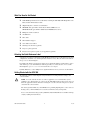
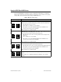
You can remove the board from the enclosure to solder components into place. To remove the board,
complete the following steps.
1.
Disconnect the 100-pin cable from the SCB-100, if connected.
2.
Remove the grounding screws on either side of the top cover with a Phillips #1 screwdriver.
3.
Open the top cover.
4.
Loosen the strain-relief screws with a Phillips #2 screwdriver.
5.
Remove the signal wires from the screw terminals.
6.
Remove the board mount screws and 100-pin connector screws.
7.
Tilt the board up and pull it out of the enclosure.
SCB-100 Installation Guide
8
ni.com