1
PSC4010
Reference Manual
PSC4010
Reference Manual
1. Introduction . . . . . . . . . . . . . . . . . . . . . . . . . . . . . . . . . . . . . . . . . . . . . . . . . . . . . . . .1
1.1 Customer Service . . . . . . . . . . . . . . . . . . . . . . . . . . . . . . . . . . . . . . . . . . . . . . . . . . . . . .1
1.2 Standard Equipment . . . . . . . . . . . . . . . . . . . . . . . . . . . . . . . . . . . . . . . . . . . . . . . . . . . .1
1.3 Safety information . . . . . . . . . . . . . . . . . . . . . . . . . . . . . . . . . . . . . . . . . . . . . . . . . . . . .2
2. Calibrator Interface . . . . . . . . . . . . . . . . . . . . . . . . . . . . . . . . . . . . . . . . . . . . . . . . . .4
2.1 Main Display . . . . . . . . . . . . . . . . . . . . . . . . . . . . . . . . . . . . . . . . . . . . . . . . . . . . . . . . .5
2.2 Menu Bar . . . . . . . . . . . . . . . . . . . . . . . . . . . . . . . . . . . . . . . . . . . . . . . . . . . . . . . . . . . .6
2.3 Cursor control / Setpoint control . . . . . . . . . . . . . . . . . . . . . . . . . . . . . . . . . . . . . . . . . . .9
3. Using Measure Modes . . . . . . . . . . . . . . . . . . . . . . . . . . . . . . . . . . . . . . . . . . . . . . .10
3.1 Measuring volts, millivolts and frequency . . . . . . . . . . . . . . . . . . . . . . . . . . . . . . . . . . .10
3.2 Measuring mA . . . . . . . . . . . . . . . . . . . . . . . . . . . . . . . . . . . . . . . . . . . . . . . . . . . . . . . .10
3.3 Measuring mA with Loop Power . . . . . . . . . . . . . . . . . . . . . . . . . . . . . . . . . . . . . . . . . .11
4. Using Source Modes . . . . . . . . . . . . . . . . . . . . . . . . . . . . . . . . . . . . . . . . . . . . . . . .11
4.1 Setting 0% and 100% Output Parameters . . . . . . . . . . . . . . . . . . . . . . . . . . . . . . . . . . .11
4.2 Using the Automatic Output Functions . . . . . . . . . . . . . . . . . . . . . . . . . . . . . . . . . . . . . .12
4.3 Sourcing mA . . . . . . . . . . . . . . . . . . . . . . . . . . . . . . . . . . . . . . . . . . . . . . . . . . . . . . . .12
4.4 Simulating a Transmitter . . . . . . . . . . . . . . . . . . . . . . . . . . . . . . . . . . . . . . . . . . . . . . . .13
4.5 Sourcing volts . . . . . . . . . . . . . . . . . . . . . . . . . . . . . . . . . . . . . . . . . . . . . . . . . . . . . . . .14
4.6 Sourcing millivolts . . . . . . . . . . . . . . . . . . . . . . . . . . . . . . . . . . . . . . . . . . . . . . . . . . . . .14
4.7 Sourcing frequency . . . . . . . . . . . . . . . . . . . . . . . . . . . . . . . . . . . . . . . . . . . . . . . . . . . .15
4.8 Sourcing a pulse train . . . . . . . . . . . . . . . . . . . . . . . . . . . . . . . . . . . . . . . . . . . . . . . . . .15
5. Remote Operation . . . . . . . . . . . . . . . . . . . . . . . . . . . . . . . . . . . . . . . . . . . . . . . . . .16
5.1 Setting up the RS-232 Port for Remote Control . . . . . . . . . . . . . . . . . . . . . . . . . . . . . . .16
5.2 Changing Between Remote and Local Operation . . . . . . . . . . . . . . . . . . . . . . . . . . . . .17
5.3 Using Commands . . . . . . . . . . . . . . . . . . . . . . . . . . . . . . . . . . . . . . . . . . . . . . . . . . . . .17
5.4 Remote Commands and Error Codes . . . . . . . . . . . . . . . . . . . . . . . . . . . . . . . . . . . . . .21
5.5 Entering Commands . . . . . . . . . . . . . . . . . . . . . . . . . . . . . . . . . . . . . . . . . . . . . . . . . . .23
6. Specifications
. . . . . . . . . . . . . . . . . . . . . . . . . . . . . . . . . . . . . . . . . . . . . . . . . . . . .28
7. Maintenance / Warranty . . . . . . . . . . . . . . . . . . . . . . . . . . . . . . . . . . . . . . . . . . . . . .30
7.1 Replacing Batteries . . . . . . . . . . . . . . . . . . . . . . . . . . . . . . . . . . . . . . . . . . . . . . . . . . . .30
7.2 Cleaning the Unit . . . . . . . . . . . . . . . . . . . . . . . . . . . . . . . . . . . . . . . . . . . . . . . . . . . . .30
7.3 Service Center Calibration or Repair . . . . . . . . . . . . . . . . . . . . . . . . . . . . . . . . . . . . . .30
7.4 Replacement Parts & Accessories . . . . . . . . . . . . . . . . . . . . . . . . . . . . . . . . . . . . . . . .30
7.5 Warranty . . . . . . . . . . . . . . . . . . . . . . . . . . . . . . . . . . . . . . . . . . . . . . . . . . . . . . . . . . . .30
1. Introduction
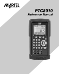
The Martel PSC4010 Multifunction Process Calibrator is a handheld, battery-operated
instrument that measures and sources electrical and physical parameters. The calibrator has
the following features and functions:
• A graphics display. The display can be used to source and measure volts, current,
frequency, and to source pulse trains.
• Five setpoints in each range for increasing/decreasing output
• An interactive menu
• Complete RS232 interface for remote control
1.1 Customer Service
Instrumentation.com
a Shelby Jones Company
8800 West Chester Pike
Upper Darby, PA 19082
Toll Free 1-800-346-4620 office 610-446-6600
www.instrumentation.com
fax610-449-7010
1.2 Standard Equipment
Check to see if your calibrator is complete. It should include:
PSC4010 Calibrator, Instruction Manual, Test Leads, Rubber Boot, NIST Certificate
1
1.3 Safety information
Symbols Used
The following table lists the International Electrical Symbols. Some or all of these symbols
may be used on the instrument or in this manual.
Symbol
Description
AC (Alternating Current)
AC-DC
Battery
CE Complies with European Union Directives
DC
Double Insulated
Electric Shock
Fuse
PE Ground
Hot Surface (Burn Hazard)
Read the User’s Manual (Important Information)
Off
On
Canadian Standards Association
The following definitions apply to the terms “Warning” and “Caution”.
• “Warning” identifies conditions and actions that may pose hazards to the user.
• “Caution” identifies conditions and actions that may damage the instrument being used.
2
Use the calibrator only as specified in this manual, otherwise injury and damage to the
calibrator may occur.
Warning
To avoid possible electric shock or personal injury:
• Do not apply more than the rated voltage. See specifications for supported ranges.
• Follow all equipment safety procedures.
• Never touch the probe to a voltage source when the test leads are plugged into the current
terminals.
• Do not use the calibrator if it is damaged. Before you use the calibrator, inspect the case.
Look for cracks or missing plastic. Pay particular attention to the insulation surrounding the
connectors.
• Select the proper function and range for your measurement.
• Make sure the battery cover is closed and latched before you operate the calibrator.
• Remove test leads from the calibrator before you open the battery door.
• Inspect the test leads for damaged insulation or exposed metal. Check test leads continuity.
Replace damaged test leads before you use the calibrator.
• When using the probes, keep your fingers away from the probe contacts. Keep your fingers
behind the finger guards on the probes.
• Connect the common test lead before you connect the live test lead. When you disconnect
test leads, disconnect the live test lead first.
• Do not use the calibrator if it operates abnormally. Protection may be impaired. When in
doubt, have the calibrator serviced.
• Do not operate the calibrator around explosive gas, vapor, or dust.
• Disconnect test leads before changing to another measure or source function.
• When servicing the calibrator, use only specified replacement parts.
• To avoid false readings, which could lead to possible electric shock or personal injury,
replace the battery as soon as the battery indicator appears.
Caution
To avoid possible damage to calibrator or to equipment under test:
• Use the proper jacks, function, and range for your measurement or sourcing application.
3
2. Calibrator Interface
Figure 1 shows the location of the input and output connections on the calibrator, while Table
1 describes their use.
F1
F2
7
8
9
4
5
6
1
2
3
–
0
.
F3
5
HOME
CE
ENTER
3
4
1
2
Figure 1. Input/Output Terminals
Table 1: Input and Output Terminals
4
No.
Name
Description
1,2
Source/Measure
V, Hz
Terminals for sourcing and measuring voltage, frequency,
pulse train
3,4
Source/Measure
mA terminals
Terminals for sourcing and measuring current
5
Serial port
Connects calibrator to a PC for remote control.
Figure 2 shows the location of the keys on the calibrator. Table 2 lists the functions of each
key.
1
F1
5
F2
7
8
9
4
5
6
1
2
3
–
0
.
F3
3
4
HOME
CE
ENTER
2
Figure 2. Keypad
Table 2. Key Functions
No.
Name
Function
1
Function Keys F1, F2, F3
Used to operate the menu bar at the bottom of the calibrator
display. F1 is used for selecting options in the left box, F2 for
the center box, and F3 for the right box.
2
Home
Returns to home menu on the menu bar.
3
Power
Turns calibrator on and off.
4
Cursor Control Key
Left and right arrow keys are used to select which decade to
be changed in output value. Up and down arrow keys are used
to increase, decrease, or ramp output value.
5
Numeric Keypad
Allows user to enter Numeric values.
2.1 Main Display
2
1
mA IN
-25.00%
4
0.000 mA
MENU
3
LIGHT
Figure 3. Display
5
The display of the calibrator is shown in Figure 3.
The menu bar is used to setup the display to perform the desired function.
Table 3 explains the different parts of the display:
Table 3: Display Functions
No.
Name
Description
1
Primary Parameters
Determine what parameter is going to be measured or
sourced.
The available options are: VOLTS, FREQ (frequency), PULSE,
mA, mA IN LOOP and mA 2W SIM.
2
Input/Output control
Switches between input mode (read), and output mode
(source).
3
Units
Shows what unit the measurement or source value is in.
Available options for FREQ and PULSE are CPM, Hz, or KHz
4
Numeric Displays
Display the numeric values of the signal being measured, or
sourced. An “OL” reading indicates an out of range or overload
condition.
2.2 Menu Bar
The parameters on the display are controlled by the menu bar, which is located at the bottom
of the LCD. The function keys (F1, F2, and F3) are used to navigate through all the levels and
choices of the menu bar. Refer to the menu tree for a clarification on the layout of all the
levels.
The top level of the menu is the home menu. It can be accessed anytime by pressing the
HOME key. There are three variations of the home menu: the input home menu, the output
home menu, and the pulse home menu.
In the input home menu the only active options are [MENU] and [LIGHT]. The [MENU] option
is used to enter the next level of the menu bar, the main menu. Press the corresponding
function key (F1) to enter the main menu. The [LIGHT] option is used to turn on the LCD
back light. Press the corresponding function key (F2) to turn on the back light.
In the output home menu there are three active options, [MENU], [LIGHT] and [STEP] or
[RAMP]. The first two options work the same as in the input home menu. The third option is
selectable in the Auto Function Menu and is used to turn on and off the selected auto
function. See Section 4.2, Using the Automatic Output Functions. Also leaving this menu or
pressing the Home button will stop the auto functions.
6
The pulse home menu also has three active options, [MENU], [TRIG], and [COUNTS]. The
[TRIG] and [COUNTS] options are used for pulse simulation. The function of these options is
explained in Section 4.2-6 (Sourcing a Pulse).
The next level of the menu bar is the main menu. The levels under the main menu depend on
what mode the calibrator is in.
The main menu has two active options [CONFIG] and [MORE].
Choosing [CONFIG] calls up the parameter selection menu. [MORE] enters the next menu
level.
CONFIG
MORE
The Auto Function Menu is the next menu if you are in source mode. Its options are [AUTO
FUNC], [NEXT] and [DONE]. [AUTO FUNC] allows you to adjust the Automatic Output
Function parameters. [NEXT] proceeds to the next menu level and [DONE] returns to the
home menu. See Section 4.2,Using the Automatic Output Functions.
The contrast menu is usually the next menu level. Its options are [CONTRAST], [NEXT], and
[DONE]. The [CONTRAST] option is used to adjust contrast. [NEXT] proceeds to the auto off
main menu, and [DONE] returns to home menu. Contrast is adjusted using the arrow options,
which are available after choosing [CONTRAST].
NOTE: The PSC4010 calibrator offers a wide range contrast adjustment feature to
accommodate operation in extreme temperatures.
In certain cases making large changes in contrast may render the display difficult to read
under normal conditions. If this occurs and the display is too dim or dark to read, proceed
with the following process to set the contrast back to a default setting.
1. Turn on the unit while holding down the “HOME” key.
2. Hold the key down for a count of 10 seconds to restore contrast default settings.
If the display is so dim that you cannot tell if the unit is on or off, use the backlight key to
determine if the power is on or off.
The auto off main menu contains the options [AUTO OFF], [NEXT], and [DONE].
The [AUTO OFF] option is used to turn the automatic shutoff on and off and set the amount of
time the unit needs to stay dormant to shut off. [NEXT] and [DONE] both return to home menu.
When the calibrator is in the frequency or pulse mode, the frequency level menu is added
after the main menu. The options available in this menu are [FREQ LEVEL], [NEXT], and
7
[DONE]. The [FREQ LEVEL] option is used to adjust the amplitude of the wave. [NEXT] is
used to access the contrast main menu, and [DONE] returns to the home menu.
The parameter selection menu is called up when [CONFIG] is selected from the main menu.
It contains the following options: [SELECT], [NEXT], and [DONE]. When the display is
selected, a parameter will start to flash. Use the [SELECT] option to change the parameter,
and the [NEXT] option to switch to another variable. [DONE] returns to the home menu and
enables the selected mode.
8
2.3 Cursor control / Setpoint control
The output value can be controlled by the four cursor control arrows on the keypad. By
pressing one of the arrows a cursor will be added to the display under the last digit of the
output value. The left and right arrow keys are used to select which decade to be changed in
the output value. The up and down arrow keys are used to increase, decrease, or ramp the
output value.
The menu bar will change to the setpoint menu with the touch of any one of the four arrow
keys.
The three function keys are associated with 0, 25, and 100% values, respectively. 0 and 100%
values can be stored by entering a value and then holding down the corresponding function
key. The 25% key will then automatically step through the 25% values.
Home Menu
LIGHT
MENU
Selection Menu
CONFIG
Parameter Selection
SELECT
NEXT
DONE
Home Menu
MENU
LIGHT
MORE
If calibrator is in
Source mode
Auto Function Menu
AUTO FUNC NEXT
DONE
If calibrator is in
Frequency Out
or Pulse mode
Frequency Level
FREQ LEVEL NEXT
DONE
Home Menu
LIGHT
MENU
Contrast Menu
CONTRAST NEXT
DONE
Auto Off Menu
AUTO OFF NEXT
DONE
Home Menu
MENU
LIGHT
Figure 4. The Menu Tree
9
3. Using Measure Modes
3.1 Measuring volts, millivolts and frequency
The calibrator can measure volts or frequency on these jacks. To make the desired
measurements, follow these steps:
1. Select the [CONFIG] option from the main menu.
2. Select the desired parameter for measurement.
3. Connect leads as shown in Figure 5.
VOLTS IN
+
MEASURE / SOURCE
3W
mA+
–
+
V
Ω
Hz
–
4W
mA–
-0.001 V
MENU
LIGHT
Figure 5. Measuring Volts and Frequency with Input/Output Terminals
3.2 Measuring mA
To measure mA follow these steps:
1. Select the [CONFIG] option from the main menu.
2. Choose [mA] from the primary parameters.
3. Make sure the input/output control is set to IN.
4. Connect leads as shown in Figure 6.
mA IN
-25.00%
+
MEASURE / SOURCE
3W
mA+
–
0.000 mA
MENU
4W
mA–
LIGHT
Figure 6. Measuring mA with Input/Output Terminals
10
+
V
Ω
Hz
–
3.3 Measuring mA with Loop Power
To test a 2-wire, loop powered transmitter that is disconnected from wiring, use the loop
power function. This function activates a 24V supply in series with the current measuring
circuit. To use this option proceed as follows:
To measure mA with loop power follow these steps:
1. Use the [CONFIG] option from the main menu to select mA IN LOOP.
2. Connect leads as shown in Figure 7.
+–
MEASURE / SOURCE
3W
mA+
4W
mA–
+
V
Ω
Hz
–
Figure 7. Connection Using Current Loop
4. Using Source Modes
The calibrator can generate calibrated signals for testing and calibrating process instruments.
It can source voltages, currents, resistances, frequencies and pulses.
4.1 Setting 0% and 100% Output Parameters
To set the 0% and 100% points, use the following steps:
1. Select the [CONFIG] option from the main menu, and choose the desired primary
parameter.
2. Select output [OUT] from the input/output control, and enter the desired value. For
example select [VOLTS OUT].
3. Enter 5V with the keypad and press Enter.
4. Press any one of the four cursor control arrows to display the setpoint control menu.
5. Hold down the Function Key that corresponds to 0% [F1]. 0% will flash and the setpoint is
stored.
6. Repeat these steps, entering 20V and holding the Function Key that corresponds to 100%
[F3].
7. Use the [F2] key to step in either 25% or 10% increments.
4.1-1 Stepping the current output
To use the 25% function with mA output, follow these steps:
1.
Select the [CONFIG] option from the main menu, and choose mA.
2.
Use the 25% key to cycle between 4 mA and 20 mA in 25 % intervals.
11
4.2 Using the Automatic Output Functions
There are two automatic output functions, step and ramp. The selected function can be
turned on and off using the Output Home Menu. The Automatic Output Function parameters
can be set in the Auto Function Menu.
Parameters include:
1. Which auto function will be available (Step or Ramp).
2. The Auto Function Time, time between steps for step and time to get from over one limit
to the next for ramp.
3. Step Size, the step size can be set to either 10% or 25%
The limits for the ramp and step functions are set to the 0% and 100% values. See Section
4.1 Setting 0% and 100% Output Parameters. Steps are in either 10% or 25% increments from
the 0% value to the 100% value.
4.3 Sourcing mA
To source a current, follow these steps:
1. Select the [CONFIG] option from the main menu. Choose [mA] from the primary
parameters.
2. Switch to input/output control, and select output [OUT].
3. Connect the leads to the mA terminals, as shown in Figure 8.
4. Enter the desired current using the keypad.
1000 ohms max.
+
UUT
MEASURE / SOURCE
3W
mA+
–
4W
mA–
+
V
Ω
Hz
–
Figure 8. Connections for Sourcing Current
-25.00 %
mA OUT
0.000 mA
MENU
12
LIGHT
4.3-1 HART™ Resistor Selection
The PSC4010 can be set-up so that the 250 ohm resistor required for Hart™ configuration
devices resides inside the PSC4010. Enabling the PSC4010's internal 250 ohm resistor
eliminates the need to manually add a series resistor during a Hart™ calibration process.
NOTE: When the PSC4010's internal 250 resistor is enabled, maximum load driving
capability drops from 1000 ohms @ 20mA to 750 ohms @20mA.
Enable/Disable Procedure
1. Remove the battery cover and remove the 2 screws that are at the top of the case.
2. Remove the 2 screws on the bottom or lower portion of the case.
3. Gently remove the top half of the case from the bottom.
4. Figure 9. shows the location of the Hart™ jumpers.
Figure 9.
4.4 Simulating a Transmitter
To have the calibrator supply a variable test current to a loop in place of a transmitter, follow
these steps:
1. Select the [CONFIG] option from the main menu.
2. Choose mA simulation from the primary parameters [mA 2W SIM], and enter the desired
current.
3. Connect the 24V loop as shown in Figure 10.
UUT
–
30 VDC
MAX
LOOP
POWER
SUPPLY
+
+
–
MEASURE / SOURCE
3W
mA+
4W
mA–
+
V
Ω
Hz
–
Figure 10. Connections for Simulating a Transmitter
13
0.00%
mA 2W SIM
4.000 mA
MENU
STEP
LIGHT
4.5 Sourcing volts
To source volts follow these steps:
1. Select the [CONFIG] option from the main menu.
2. Choose [VOLTS] from the primary parameters. Switch to input/output control and select
output [OUT].
3. Connect the leads for the voltage source terminals, as shown in Figure 11.
4. Enter the voltage using the keypad.
4.6 Sourcing millivolts
To source volts follow these steps:
1. Select the [CONFIG] option from the main menu.
2. Choose [mV] from the primary parameters. Switch to input/output control and select output
[OUT].
3. Connect the leads for the voltage source terminals, as shown in Figure 11.
4. Enter the millivolts value using the keypad.
+
MEASURE / SOURCE
3W
mA+
UUT
4W
mA–
+
V
Ω
Hz
–
–
Figure 11. Connections for Sourcing Voltage and Frequency
VOLTS OUT
0.000 V
MENU
14
LIGHT
STEP
4.7 Sourcing frequency
To source a signal use these steps:
1. Select the [CONFIG] option from the main menu and select frequency from the primary
parameters.
2. Select output, and than choose the frequency units.
3. Connect the leads to the frequency output terminals as shown in Figure 12.
4. Enter the desired frequency using the keypad.
5. To change the amplitude, select [FREQ LEVEL] from frequency level menu.
6. Enter the amplitude.
5.0 Vpp
PULSE
1.0 kHz
1.0 kHz
MENU
TRIG
COUNTS
5.0 Vpp
FREQ OUT
MENU
LIGHT
STEP
4.8 Sourcing a pulse train
The calibrator can produce a pulse train with an adjustable number of pulses at a desired
frequency. For example, setting the frequency to 60Hz and the number of pulses to 60 would
produce 60 pulses for a period of 1 second. To source a pulse, use the same connection as
for frequency, and proceed as follows:
1. Select the [CONFIG] option from the main menu and select pulse from the primary
parameters.
2. Choose the desired unit and enter the frequency using the keypad.
3. Select the [COUNTS] function from the home menu to enter the number of pulses. Use
[TRIG] to start and stop the signal.
4. The amplitude of the pulse can be adjusted in the same manner as for frequency.
15
5. Remote Operation
The calibrator can be remotely controlled using a PC terminal, or by a computer program
running the calibrator in an automated system. It uses an RS-232 serial port connection for
remote operation. With this connection the user can write programs on the PC, with Windows
languages like Visual Basic to operate the calibrator, or use a Windows terminal, such as
Hyper Terminal, to enter single commands. Typical RS-232 remote configurations are shown
in Figure 12.
COM PORT
USB PORT
OR
F1
F2
7
8
9
4
5
6
1
2
3
–
0
.
F3
HOME
CE
ENTER
Optional RS-232 or USB Cable
(See section 7.4)
Figure 12. Calibrator-to-Computer Connection
5.1 Setting up the RS-232 Port for Remote Control
Note: The RS-232 connection cable should not exceed 15m unless the load capacitance
measured at connection points is less than 2500pF.
Serial parameter values:
9600 baud
8 data bits
1 stop bit
no parity
Xon/Xoff
EOL (End of Line) character or CR (Carriage Return) or both
To set up remote operation of the calibrator on the Windows Hyper Terminal, connected to a
COM port on the PC as in Figure 23, use the following procedure:
1. Start Hyper Terminal (located in Accessories/Communications of the Windows Start
menu)
2. Select New Connection.
3. For Name enter PSC4010. Select the serial port that the unit is connected to.
4. Enter the above information for port settings.
5. Select ASCII setup from File/Properties/Settings and mark these choices:
Echo typed characters locally
Wrap lines that exceed terminal width
16
6. Select Ok
7. To see if the port works enter *IDN?. This command will return information on the unit.
5.2 Changing Between Remote and Local Operation
There are three modes of operation of the calibrator, Local, Remote, and Remote with
Lockout. Local mode is the default mode. Commands may be entered using the keypad on
the unit or using a computer. In Remote mode the keypad is disabled, and commands may
only be entered using a computer, but choosing [GO TO LOCAL] from the menu on the
calibrator display will restore keypad operation. In Remote with Lockout, the keypad can not
be used at all. To switch modes proceed as follows:
1. To enable Remote mode, type in the serial command REMOTE at the computer terminal.
2. To enable Remote with Lockout, type in REMOTE and LOCKOUT in either order.
3. To switch back to local operation enter LOCAL at the terminal. This command also turns off
LOCKOUT if it was on. For more information on commands refer to the Remote Commands
section.
5.3 Using Commands
5.3-1 Command types
Refer to the Section on Remote Commands for all available commands.
The calibrator may be controlled using commands and queries. All commands may be
entered using upper or lower case. The commands are divided into the following categories:
Calibrator Commands
Only the calibrator uses these commands. For example
MEAS DCV
tells the calibrator to measure voltage.
Common Commands
Standard commands used by most devices. These commands always begin with an "*". For
example
*IDN?
tells the calibrator to return its identification.
Query Commands
Commands that ask for information. They always end with a "?". For example:
FUNC?
Returns the current modes of the calibrator.
Compound Commands
Commands that contain more than one command on one line. For example:
MEAS_DCV;FUNC?
Sets the calibrator to volts measure and queries the function type.
17
Overlapped Commands
Commands that require more time to execute than normal. The command *WAI can be used
after the overlapped command to tell the calibrator to wait until the command finishes before
executing the next command. For example:
TRIG; *WAI
Triggers the pulse train. Once the pulse train has been triggered, the calibrator can proceed
to the next command.
Sequential Commands
Commands that are executed immediately after the are entered. This type includes most of
the commands.
5.3-2 Character Processing
The data entered into the calibrator is processed as follows:
• ASCII characters are discarded if their decimal equivalent is less than 32 (space), except 10
(LF) and 13 (CR):
• Data is taken as 7-bit ASCII
• The most significant data bit is ignored.
• Upper or lower case is acceptable.
5.3-3 Response Data Types
The data returned by the calibrator can be divided into four types:
Integer
For most computers and controllers they are decimal numbers ranging from -32768 to 32768.
For example:
*ESE 140; *ESE? returns 140
Floating
Numbers that have up to 15 significant figures and exponents. For example:
FREQ_LEVEL? returns 5.000000E-00
Character Response Data (CRD)
Data returned as keywords. For example:
FUNC? returns DCV
Indefinite ASCII (IAD)
Any ASCII characters followed by a terminator. For example:
*IDN? returns MARTEL, PSC4010, 250, 1.00
18
5.3-4 Calibrator Status
Status registers, enable registers, and queues provide status information on the calibrator.
Each status register and queue has a summary bit in the Serial Poll Status Byte. Enable
registers generate summary bits in the Serial Poll Status Byte. The following is a list of
registers and queues along with their function.
Serial Poll Status Byte (STB)
The STB is sent when the calibrator responds to the *STB? command. Figure 24
demonstrates how it functions. Cleared when power is reset.
Service Request Enable Register (SRE)
Enables or disables the bits of the STB. Cleared when power is reset. Setting bits to 0
disables them in the STB. Setting the bits to 1 enables them. Bit assignments for the SRE and
the STB are shown below.
7
6
5
4
3
2
1
0
0
MSS
ESB
0
EAV
0
0
0
MSS
Master Summary Status. Set to 1 when ESB or EAV are 1 (enabled). Read using
the *STB? command.
ESB
Set to 1 when at least one bit in ESR is 1.
EAV
Error Available. An error has been entered into the error queue, and may be read
using the Fault? command.
Event Status Register (ESR)
A two-byte register, in which the lower bits represent conditions of the Calibrator. Cleared
when read and when power is reset.
Event Status Enable Register (ESE)
Enables and disables bits in the ESR. Setting a bit to 1 enables the corresponding bit in the
ESR, and setting it to 0 disables the corresponding bit. Cleared at power reset. Bit
assignments for the ESR and the ESE respectively are shown below.
15
14
13
12
11
10
9
8
0
0
0
0
0
0
0
0
19
7
6
5
4
3
2
1
0
PON
0
CME
EXE
DDE
QYE
0
OPC
PON
Power On. Set to 1 if power was turned on and off before the Event Status Register
was read.
CME
Command Error. Set to 1 when the calibrator receives an invalid command.
EXE
Execution Error. Set to 1 when the calibrator runs into an error while executing is
last command. A parameter that has too significant figures may cause such an
error.
DDE
Device-dependent Error. Set to 1 when, for example, the output of the calibrator is
overloaded.
QYE
Query Error.
OPC
Operation Complete. Set to 1 when the calibrator has finished executing all
commands before the command *OPC was entered.
Error Queue
If an error occurs due to invalid input or buffer overflow, its error code is sent to the error
queue. The error code can be read from the queue with the command FAULT?. The error
queue holds 15 error codes. When it is empty, FAULT? returns 0. The error queue is cleared
when power is reset or when the clear command *CLS is entered.
Input Buffer
Calibrator stores all received data in the input buffer. The buffer holds 250 characters. The
characters are processed on a first in, first out basis.
20
5.4 Remote Commands and Error Codes
The following tables list all commands, and their descriptions, that are accepted by the
calibrator.
Table 5: Common Commands
Command
Description
*CLS
*CLS (Clear status.) Clears the ESR, the error queue, and the RQS bit in the status byte.
Terminates pending Operation Complete commands
*ESE
Loads a byte into the Event Status Enable register.
*ESE?
Returns the contents of the Event Status Enable register.
*ESR?
Returns the contents of the Event Status register and clears the register.
*IDN?
Identification query. Returns the manufacturer, model number, and firmware revision level
of the Calibrator.
*OPC
Enables setting of bit 0 (OPC for "Operation Complete") in the Event Status Register to 1
when all pending device operations are complete.
*OPC?
Returns a 1 after all pending operations are complete. This command causes program
execution to pause until all operations are complete.
*RST
Resets the state of the instrument to the power-up state. This command holds off
execution of subsequent commands until it is complete.
*SRE
Loads a byte into the Service Request Enable register.
*SRE?
Returns the byte from the Service Request Enable register.
*STB?
Returns the status byte.
*WAI
Prevents further remote commands from being executed until all previous remote
commands have been executed.
Table 6: Calibrator Commands
Command
Description
CAL_START
Puts the calibrator in calibration mode
FAULT?
Returns the error code of an error that has occurred
FREQ_LEVEL
Sets the frequency and pulse amplitude
FREQ_LEVEL?
Returns the frequency and pulse amplitude
FREQ_TYPE
Set the frequency output to continuous (frequency) or pulse.
FREQ_TYPE?
Returns frequency output type, continuous or pulse
FREQ_UNIT
Sets the unit for frequency and pulse
FREQ_UNIT?
Returns the unit for frequency and pulse
FUNC?
Returns the current mode of the calibrator
LOCAL
Returns user to manual operation of the calibrator
LOCKOUT
Locks out the keypad of the calibrator, and allows for remote operation only
MEAS
Sets the mode for measuring of the calibrator
OUT
Sets the output of the calibrator
OUT?
Returns the output of the calibrator
PULSE_CNT
Sets the number of pulses for the pulse train
21
Command
PULSE_CNT?
Description
Returns the number of pulses in the pulse train
REMOTE
Puts the calibrator in remote mode
SIM
Sets the output for mA simulation
SIM?
Returns the output of the mA simulation
TRIG
Starts and stops the pulse train in pulse mode
TRIG?
Returns TRIGGERED when a pulse train is on. Returns UNTRIGGERED when the pulse
train is off.
VAL?
Returns the measured values
V_RANGE
Sets voltage range
V_RANGE?
Returns voltage range
Table 7: Parameter units
Units
Meaning
MA
milliamps of current
MV
Voltage in millivolts
V
CPM
Hz
KHz
Voltage in volts
Frequency in cycles per minute
Frequency in Hertz
Frequency in kiloHertz
Table 8: Error codes
Error Number
22
Error Description
100
A non-numeric entry was received where it should be a numeric entry
101
Too many significant digits entered
102
Invalid units or parameter value received
103
Entry is above the upper limit of the allowable range
104
Entry is below the lower limit of the allowable range
105
A required command parameter was missing
110
An unknown command was received
112
The serial input buffer overflowed
113
Too many entries in the command line
114
The serial output buffer overflowed
115
Output is overloaded
116
Calibrator not in pulse train mode when TRIG was received
117
An invalid FREQ_TYPE was received
5.5 Entering Commands
Commands for the calibrator may be entered in upper or lower case. There is at least one
space required between the command and parameter, all other spaces are optional. Almost
all commands for the calibrator are sequential, any overlapped commands will be indicated
as such. This section will briefly explain each of the commands and describe their general
use, which will include any parameters that may be entered with the command as well as
what the output of the command is.
5.5-1 Common Commands
*CLS
Clears the ESR, the error queue and the RQS bit. Also terminates all pending operations.
When writing programs, use before each procedure to avoid buffer overflow.
*ESE
Loads a byte into the Event Status Enable register. The command is entered with a decimal
number that, when converted to binary, enables the right bits in the Event Status Register. For
example:
*ESE 133
When 133 is converted to binary it is 10000101. Bits 7, 2, and 0 will be enabled.
*ESE?
Returns the contents of the Event Status Enable register. The value returned is a decimal. For
example, if the register has the following settings:
10000101
than the value returned will be 133.
*ESR?
Returns the contents of the Event Status Register in decimal form. For example:
If the ESR contains 10111001, *ESR? will return 185.
*IDN?
Returns the manufacturer, model number, and firmware revision of the Calibrator. For
example:
*IDN? will return MARTEL, PSC4010, 250, 1.00
*OPC
Enables the Operation Complete setting in the ESR. This setting makes it possible to check if
an operations is complete after it has been initialized.
For example this operation could be used with the command TRIG.
23
*OPC?
Returns 1 when all operations are complete, and causes program execution to pause until all
the operations are complete. For example:
TRIG ; *OPC? will return a 1 when the pulse train initiated by TRIG is complete.
*RST
Resets the state of calibrator to the power-up state. All subsequent commands are held off
until the execution of the command is complete.
*SRE
Loads a byte into the Service Request Enable register. A decimal number must be entered,
which when converted to binary, corresponds to the correct settings.
For example:
*SRE 8 enters the binary number 00001000 to the SRE. This enables bit 3. Bit 6 is not
used.
*SRE?
Returns a byte from the SRE. The byte is returned in decimal format. For example:
If 40 is returned, bits 5 and 3 are enabled.
*STB
Returns the status byte in decimal form from the Serial Poll Status Byte. For example;
If 72 is returned, bits 6 and 3 are enabled.
*WAI
Prevents further remote commands from being executed until all previous commands are
executed. For example:
OUT 10 MA ; *WAI ; OUT 5 V will out put 10mA and wait until output settles, than volts
command will be processed.
5.5-2 Calibrator Commands
CAL_START
Puts the calibrator in calibration mode. The main display will say CALIBRATION MODE and a
calibration menu will be displayed on the terminal.
FAULT?
Returns the error code number of an error that has occurred. The command may be entered
when the previous command did not do what it was meant to do.
24
For example, if a value for current output is entered that is bigger than the supported range
(0-24mA) FAULT? Would return:
103 which is the code number for an entry over range.
Refer to the Error Codes table for more information on error code numbers.
FREQ_LEVEL
Sets the amplitude of the wave used in the Frequency Out and Pulse modes. The range for
amplitude entered may be found in the Specifications section.
For example:
FREQ_LEVEL 5 V sets the amplitude at 5Vpp.
FREQ_LEVEL?
Returns the amplitude of the wave used in Frequency Out and Pulse modes.
FREQ_LEVEL? with the above example would return:
5.000000E+00, V
FREQ_TYPE
When in frequency mode, sets the calibrator to output a continuous wave (Frequency Out), or
a pulse train. To set the calibrator to continuous wave enter CONT after the command. To set
the calibrator to pulse enter PULSE after the command. For example:
FREQ_TYPE CONT will set the calibrator to FREQ OUT.
Note: This command does not put the calibrator in frequency mode. Use the OUT command
to put the calibrator in frequency mode.
FREQ_TYPE?
Tells whether calibrator is sourcing a pulse or a continuous wave. The command will return
CONT if the calibrator is in FREQ OUT mode, and PULSE if the calibrator is in PULSE mode.
FREQ_UNIT
Sets the unit for frequency. There are three ranges of frequencies for frequency and pulse
modes, CPM (cycles per minute), Hz, and kHz. Use this command to select the right range.
For example:
FREQ_UNIT HZ sets the frequency to Hz range
FREQ_UNIT?
Returns the frequency unit currently being used by the frequency and pulse modes.
FUNC?
Returns the current mode of the display. For example if the calibrator is set to volts FUNC?
Would return:
DCV
25
LOCAL
Restores the calibrator to local operation if it was in remote mode. Also clears LOCKOUT if the
unit was in lockout mode.
MEAS
Sets the display to measure mode. The command is followed by any of the parameters
except for pulse and mA sim, which are source only. Enter DCI for mA, DCV for volts, DCMV
for millivolts, FREQUENCY for frequency, and PRESSURE for pressure. For example:
MEAS DCV sets the display mode to VOLTS IN
OUT
Sets the output of the calibrator. This command may be used to output mA, volts, frequency,
temperature, and ohms. Frequency output, which is set by the command FREQ_TYPE, is
either continuous or pulse. The calibrator is automatically set to source mode when OUT is
entered. A number and its unit must follow the command. See Table 7. (Parameter Units) for a
list of available units. For example:
OUT 10 MA sets the calibrator to mA OUT mode and sets the output to 10mA.
OUT?
Returns the output of the calibrator. Using the above example, OUT? Would return:
1.000000E-02, A
PULSE_CNT
Sets the number of pulses the calibrator will produce when it is triggered while in pulse mode.
For example;
PULSE_CNT 3000 will set the number of pulses to 3000.
PULSE_CNT?
Returns the number of pulses in the pulse train. Using the above example, the returned value
would be:
3000
REMOTE
Puts the calibrator in remote mode. From the remote mode the user can still use the keypad
to get back to local unless the command LOCKOUT was entered before REMOTE. Than the
keypad is totally locked out, and the user has to send the LOCAL command to get back to
local operation.
26
SIM
Sets the output for current simulation. This command also switches the calibrator into mA
simulation mode. A number and a unit must be entered after the command. For example:
SIM 5 MA sets the current simulation at 5 mA
SIM?
Returns the output of the current simulation. With the example above, the output would be:
5.000000E-03, A
TRIG
Starts and stops the pulse train when the calibrator is in pulse mode. The parameters of the
pulse train are set by commands PULSE_CNT, and FREQ_LEVEL. Entering TRIG initializes
the train. Entering the command while the pulse train is running stops it.
TRIG?
Returns TRIGGERED if the pulse train is running, and returns UNTRIGGERED when the pulse
train is not running. Returns NONE when the calibrator is not in pulse mode.
VAL?
Returns the value of any measurement taking place on the display. For example, if the display
is measuring 10V, then VAL? will return:
1.000000E+01, V
V_RANGE
Sets the voltage range of the calibrator. DCV for the voltage range and DCMV for the
millivolts range.
V_RANGE?
Returns DCV or DCMV
27
6. Specifications
One year at 23°C ± 5°C, unless specified otherwise. Outside of this range the stability of the
measurements is ± 0.005% of reading/°C.
Table 9: General Specifications
Operating Temperature
-10°C to 50°C
Storage Temperature
-20°C to 70°C
Power
4 X AA batteries; Alkaline or optional rechargeable
Low battery warning
Yes
Serial Communications
Yes, ASCII
CE - EMC
EN61326: 2006, ANNEX B Criterion A
Safety
CSA C22.2 No. 1010.1: 1992
Table 10: DC Voltage Measurement/Source
Range
Accuracy (% of reading ± floor)
Read
0.000V - 20.000V
0.015% ± 2mV
Source
0.000V - 20.000V
0.015% ± 2mV
Maximum current output in voltage ranges is 3mA with an output impedance of <= 1Ω.
Table 11: Millivolts Measurement/Source
Range
Accuracy (% of reading ± floor)
Read (mV)
0.000mV - 90.000mV
0.02% ± 10μV
Source (mV)
0.000mV - 100.000mV
0.02% ± 10μV
Maximum current output in voltage ranges is 1mA with an output impedance of <= 1Ω
Table 12: DC mA Measurement/Source
Range
Accuracy (% of reading ± floor)
Read
0.000mA - 24.000mA
0.015% ± 2μA
Source
0.000mA - 24.000mA
0.015% ± 2μA
Maximum load on mA source is 1000Ω. Voltage input range on simulate mode 5V - 30V.
For units configured to support 50mA the table below shows the specification.
Range
Accuracy (% of reading ± floor)
Read
0.000mA - 52.000mA
0.02% ± 4μA
Source
0.000mA - 52.000mA
0.02% ± 4μA
Maximum load on mA source is 400Ω at 52mA. Voltage input range on simulate mode 5V - 60V.
28
Table 13: Frequency Measurement/Source
Range
Read
2.0CPM - 600.0CPM
1.0Hz - 1000.0Hz
1.00KHz - 10.00KHz
Source
Accuracy (% of reading ± floor)
0.05% ± 0.1CPM
0.05% ± 0.1Hz
0.05% ± 0.01KHz
2.0CPM - 600.0CPM
0.05%
1.0Hz - 1000.0Hz
0.05%
1.00KHz - 10.00KHz
0.125%
Input voltage amplitude range on frequency is 1V to 20V zero based square wave only.Output amplitude is
adjustable from 1V to 20V, and is a square wave with 50% duty cycle.For output frequency, a slight negative
offset of approximately -0.1V is present to assure zero crossing.
29
7. Maintenance / Warranty
7.1 Replacing Batteries
Replace batteries as soon as the battery indicator turns on to avoid false measurements. If
the batteries discharge too deeply the PSC4010 will automatically shut down to avoid battery
leakage.
Note: Use only AA size alkaline batteries or optional rechargeable battery pack.
7.2 Cleaning the Unit
Warning
To avoid personal injury or damage to the calibrator, use only the specified replacement parts
and do not allow water into the case.
Caution
To avoid damaging the plastic lens and case, do not use solvents or abrasive cleansers.
Clean the calibrator with a soft cloth dampened with water or water and mild soap.
7.3 Service Center Calibration or Repair
Only qualified service personnel should perform calibration, repairs, or servicing not covered
in this manual. If the calibrator fails, check the batteries first, and replace them if needed.
Verify that the calibrator is being operated as explained in this manual. If the calibrator is
faulty, send a description of the failure with the calibrator. Be sure to pack the calibrator
securely, using the original shipping container if it is available. To return the product to Martel
go to www.martelcalibrators.com and click on the Customer Service link. Download the RMA
form and follow the instructions. Calibration procedures and other related documents can
also be found on the website.
7.4 Replacement Parts & Accessories
CC572
C232SJ
1919896
5353050
1001-9V
Carrying Case
RS232 Cable with Miniature Plug
USB/RS232 Converter Cable with Miniature Plug
48" Stackable Testleads
Battery Adapter/Charger
7.5 Warranty
Martel Electronics Corporation warrants all products against material defects and
workmanship for a period of twelve (12) months after the date of shipment. Problems or
defects that arise from misuse or abuse of the instrument are not covered. If any product is to
be returned, a “Return Material Authorization” number must be obtained from our Customer
Service Department. This number must be indicated on the return package as notice to our
Receiving Department to accept the shipment. Any package not so marked will not be
accepted and will be returned to the shipper. Martel will not be responsible for damage as a
result of poor return packaging. Out of warranty repairs and recalibration will be subject to
specific charges. Under no circumstances will Martel Electronics be liable for any device or
circumstance beyond the value of the product.
30
0219895 1/11 Rev B