1
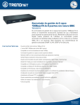
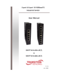
8-port 10/100TX internal power switch MIL-S800i-v2 User Manual Rev. 1.00 11-November-2008 1 Regulatory Approval - FCC Class B - UL 1950 - CSA C22.2 No. 950 - EN60950 - CE - EN55022 Class A - EN55024 Canadian EMI Notice This Class A digital apparatus meets all the requirements of the Canadian Interference-Causing Equipment Regulations. Cet appareil numerique de la classe A respecte toutes les exigences du Reglement sur le materiel brouilleur du Canada. European Notice Products with the CE Marking comply with both the EMC Directive (89/336/EEC) and the Low Voltage Directive (73/23/EEC) issued by the Commission of the European Community Compliance with these directives imply conformity to the following European Norms: EN55022 (CISPR 22) - Radio Frequency Interference EN61000-X - Electromagnetic Immunity EN60950 (IEC950) - Product Safety Five-Year Limited Warranty Transition Networks warrants to the original consumer or purchaser that each of it's products, and all components thereof, will be free from defects in material and/or workmanship for a period of five years from the original factory shipment date. Any warranty hereunder is extended to the original consumer or purchaser and is not assignable. Transition Networks makes no express or implied warranties including, but not limited to, any implied warranty of merchantability or fitness for a particular purpose, except as expressly set forth in this warranty. In no event shall Transition Networks be liable for incidental or consequential damages, costs, or expenses arising out of or in connection with the performance of the product delivered hereunder. Transition Networks will in no case cover damages arising out of the product being used in a negligent fashion or manner. Trademarks The MiLAN logo and Transition Networks trademarks are registered trademarks of Transition Networks in the United States and/or other countries. To Contact Transition Networks For prompt response when calling for service information, have the following information ready: - Product serial number and revision - Date of purchase - Vendor or place of purchase You can reach Transition Networks technical support at: E-mail: [email protected] Telephone: +1.800.260.1312 x 200 Fax: +1.952.941.2322 Transition Networks 6475 City West Parkway Eden Prairie, MN 55344 United States of America Telephone: +1.800.526.9267 Fax: : +1.952.941.2322 http://www.milan.com info@ Transition.com © Copyright 2006 Transition Networks 2 FCC Statement This Equipment has been tested and found to comply with the limits for a Class B digital device, pursuant to Part 15 of FCC rules. These limits are designed to provide reasonable protection against harmful interference in a residential installation. This equipment generates, uses, and can radiate radio frequency energy and if not stalled and used in accordance with the instruction, it may cause harmful interference to radio communications. However, there is no guarantee that interference will not occur in a particular installation. If this equipment does cause harmful interference to radio or television reception, which can be determined by turning the equipment off and on, the user is encouraged to try to correct the interference by one or more of the following measure: Reorient or relocate the receiving antenna. Increase the separation between the equipment and receiver. Connect the equipment into an outlet on a circuit different from that to which the receiver is connected. Consult the dealer or an experienced radio/TV technician for help. CE Mark Warning This is a class B product. In a domestic environment this product may cause radio interference in which case the user may be required to take adequate measures 3 Introduction The 8-port 10/100TX internal power switch is compact and attractively designed for desktop use. It is an ideal solution for small office or the SOHO network user. This switch provides wire-speed, Fast Ethernet switching function, that allows for high-performance, low-cost connections. The switch will automatically detect the speed of the device that you plug into it, allowing the use of both 10 and 100Mbps device. It features store-and-forward switching and can auto-learn and store source address. Features Conforms to IEEE 802.3 10Base-T, 802.3u 100Base-TX and 802.3x Flow control Non-blocking and full wire speed forwarding rate Store and Forward switching architecture Universal internal switch power 1.6 Gbps back plane LED on top side of case Auto-MDIX on all ports N-way Auto-Negotiation Back pressure half duplex Flow control full duplex 768Kbits packet buffer 1K MAC address table Compact size and wall mount design 4 Package Contents 8-port 10/100TX internal power switch Rubber Feet Power cord User Manual The 8 10/100BASE-TX Switch Rubber Feet Power cord User Manual Package Contents Compare the contents of your switch with the standard checklist above. If any item is missing or damaged, please contact your local dealer for service. 5 Hardware Description This section mainly describes the hardware of the 8-port 10/100TX internal power switch. Physical Dimension The physical dimensions of the 8-port 10/100TX internal power switch is 165mm(W) X 100mm(D) x 32.5mm(H). Front Panel The LED indicators are located on the upper cover of the switch. They provide a real-time indication of systematic operation status. LED Indicator The following table provides descriptions of the LED statuses and their meaning. LED Power Status Color On Green 6 Description The power of the Switch is On On Green The connection speed is 100Mbps 100M The connection speed is Off 10Mbps The port is successfully On Green connecting with the device. LNK /ACT The port is receiving or Blink transmitting data. Off No device attached. Rear Panel The Rear Panel of the 8-port 10/100TX internal power switch consists of 8x 10/100 RJ-45 Ethernet ports and one power connector. Rear Panel of the 8-port 10/100TX internal power switch RJ-45 Port: 8x 10/100N-Way auto-sensing for 10Base-T or 100Base-TX connection. Auto MDI/MDI-X: Will detect if a straight-through cable is connected to a NIC or cascaded to a hub or switch, without the need to change the cable or connector. The maximum distance between the Switch and another device is 100 meters. 7 Installation This section shows the installation procedures of the switch. Set the Switch on a sufficiently large flat space with a power outlet nearby. The surface where you put the Switch should be clean, smooth, level, and sturdy. Make sure there is enough clearance around the Switch to allow attachment of cables, power cord and air circulation. Attaching Rubber Feet A. Make sure mounting surface on the bottom of the Switch is grease and dust free. B. Remove adhesive backing from your Rubber Feet. C. Apply the Rubber Feet to each corner on the bottom of the Switch. These footpads will help protect the Switch from shock/vibration. Mounting on the Wall The switch is designed so it can mount on the wall. The bottom of the switch has two cross hook holes for mounting the switch to a wall. Follow the steps below for wall mounting the switch. 1. Using the screw as the following figure showed. The screws did not include in the package. User needs to provide their own screws. 8 2. Attach the screws to the wall so they are positioned for the hanging the switch. Do not over tighten the screws; leave some space between screws and the wall. 3. Mount the switch to the screws on the wall. Using the cross hook hole at the bottom of the switch to mount the switch on the wall Power On Connect the power cord to the power socket on the rear panel of the Switch. The other end of power cord connects to the power outlet. Check the power indicator on the upper panel to see if power is properly supplied. 9 Trouble Shooting The switch can be easily monitored through panel indicators to assist in identifying problems. This section describes common problems you may encounter and where you can find possible solutions. Diagnosing LED Indicators If Link indicator does not light up after making a connection, you may check whether network interface (e.g., a network adapter card on the attached device), network cable, or switch port is defective or not. Be sure the cable is plugged into both the Switch and corresponding device. Verified the proper cable type is used and its length does not exceed specified limits. Power If the power indicator does not turn on when the power cord is plugged in, you may have a problem with power outlet, or power cord. However, if the switch powers off after running for a while check for loose power connection, power loses or surges at power outlet. If you still cannot resolve the problem, contact your local dealer for assistance. Cabling RJ-45 Ports: Use unshielded twisted-pair (UTP) or shield twisted-pair (STP) cable for RJ-45 connections: 100Ω Category 3,4 or 5 Cable for 10Mbps connections or 100 Ω Category 5 Cable for 100Mbps connections. Also be sure that the length of any twisted-pair connection does not exceed 100 meters (328 feet). 10 Technical Specification This section provides the specifications of the 8-port 10/100TX internal power switch. IEEE 802.3 10BASE-T Ethernet, Standard IEEE 802.3u 100BASE-TX Fast Ethernet IEEE802.3x Flow Control and Back-pressure Protocol CSMA/CD Technology Store-and-Forward switching architecture Transfer Rate 14,880 pps for 10Mbps 148,800 pps for 100Mbps Connector RJ 45; Auto MDI-X on all ports MAC Address 1K Mac address table Memory Buffer 768Kbits Backplane 1.6Gbps Per port: Link/Activity LED Indicator Per port: 100M Per unit: Power 11 10Base-T: 2-pair UTP Cat. 3, 4, 5 cable Network Cable (100m), EIA/TIA-568 100-ohm STP (100m) 100Base-TX: 2-pair UTP Cat. 5 cable (100m), EIA/TIA-568 100-ohm STP (100m) Dimension Operating Temperature Operating Humidity Power Supply Power Consumption 165mm x 100mm x 32.5mm (L x W x H) 0ºC to 45ºC (32ºF to 113ºF) 5% to 95% (Non-condensing) AC 100~240V, 50~60 Hz 4.5 Watt (Maximum) EMI Compliance with FCC Class B, CE Safety Compliance with UL, cUL, CE/EN60950-1 12