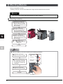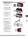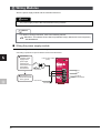
1
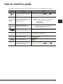
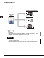
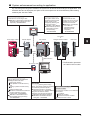
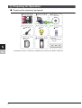
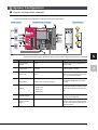
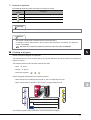
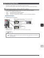
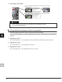
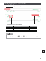
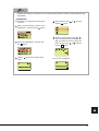
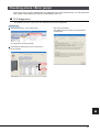
How to read this guide
The following shows the symbols used in this Quick start guide with descriptions and examples.
Symbol
P oint
Description
This symbol explains information
you need to know.
Example
Select [View] → [Comment] ( Ctrl key + F5 key). The
comment display/hide setting can be switched.
For details, refer to the following manual.
Reference
Terminology
Caution
[]
This symbol describes the
references of manuals and pages
for more details.
MELSEC-L CPU Module User's Manual
(Function Explanation, Program
Fundamentals)
: SH-080889ENG
This symbol describes the
explanations of the terminology.
Device : A place where ON/OFF or numeric values and
character string data is recorded in the
programmable controller.
This symbol describes content that
must be noted in operation.
When mounting the module, the power must be turned off.
Menu names on the menu bar
([ ] → [ ] shows drop-down menus.)
Select [Project] → [New project].
Buttons on the screen
Keys on the keyboard
()
Another procedure corresponding
to a drop-down menu (icons and
keys on the keyboard)
button
F4
key
Select [View] → [Comment] (
Ctrl
key +
F5
key).
1
Introduction
This Quick start guide explains the basic procedures for the first-time use of the Mitsubishi
programmable controller MELSEC-L series CPU module (CPU module).
You can easily understand how to use the programmable controller with this guide.
Mounting and wiring modules
Quick start
guide
100VAC
24VDC
Creating programs
X6
X7
0
X8
3
Checking operations
Reference
● Precautions
Read "SAFETY PRECAUTIONS" in the MELSEC-L CPU Module User's Manual or "Safety
Guidelines" that is an included manual of CPU module carefully.
Caution
This Quick start guide explains operations in the programmable controller system described in
"
System Configuration" (P.9).
Read the manuals referred on the following page when you design or manage the system.
"Related manuals" (P.6)
2
Operations that can be performed using
MELSEC-L series
■ Programmable controllers
The programmable controllers perform sequence control and logical operations by switching the output
of output equipment ON/OFF according to the command signal from the input equipment.
<Input equipment> <Programmable controller> <Output equipment>
Push-button
switch
Power
Data
Output interface
Input interface
Memory
Operation
Power
Program
Creating and
debugging programs
Input module
CPU module
Output module
Personal computer
Other equipment is shown below.
<Examples of input equipment>
Limit switch
Input relay
Switch
<Examples of output equipment>
Contactor
Solenoid valve
Terminology
Sequence control : Consecutively processes each control step based on the fixed order or
procedure.
Logical operations : One of the basic operation methods in programming.
Logical operations consist of three basic operations: logical AND, logical
OR, and logical NOT.
Limit switch
: A switch to stop the movement of mobile objects on both sides of a moving
apparatus for safety reasons.
Relay
: Breaks/connects the electricity with electrical switching.
Contactor
: Generally called an electromagnetic contactor to break circuits and switch
the heater.
Solenoid valve
: An electromagnet with a direct/alternating current. Connected to the output
side of the programmable controller.
3
■ Features of CPU module
MELSEC-L series programmable controllers are all-in-one programmable controllers that have the
following functions built into the CPU module. The use of these built-in functions enables you to design
a smaller-scale system.
Built-in Ethernet function
Built-in I/O function
A maximum of 16 external devices can be connected via
a hub.
The reading/writing of the device data of the CPU module
and the sending/receiving of the data of the other
connected devices can be performed to/from a personal
computer and GOT.
Single function exclusive modules become unnecessary, and
a smaller-scale system can be configured using only LCPU.
Therefore, system cost reduction can be realized.
General-purpose input function Interrupt input function Pulse catch function
Ethernet
Hub
General-purpose output function High-speed counter function
Positioning function
Vision sensor
GX Works2
GX Works2
GOT
MELSEC-L CPU Module User's Manual
(Built-in Ethernet functions): SH-080891ENG
MELSEC-L CPU Module User's Manual
(Built-in I/O functions): SH-080892ENG
* The illustration represents
L26CPU-BT.
Data logging function
Built-in CC-Link function
Logging can be performed under various conditions
using the exclusive configuration tools. The collected data
can be saved to the SD memory card in the CSV format.
I/O modules, intelligent function modules, and special function
modules, which are arranged separately, can be controlled with
the CPU module. In addition, a simple separately-configured system
can be designed by connecting multiple CPU modules using CC-Link.
*CC-Link function is only built into L26CPU-BT.
Secure data collection is possible
with just simple setting.
CC-Link
Setting
Saving to the SD
memory card in the
CSV format is
possible.
18:55:16 65,725,36,1
18:55:17 66,756,36,0
18:55:18 67,723,36,0
18:55:19 68,741,36,0
18:55:20 69,712,36,1
18:55:20 70,724,36,1
18:55:20 71,732,36,1
18:55:20 72,733,
:
CSV
format
MELSEC-L CPU Module User's Manual
(Data logging functions) : SH-080893ENG
4
MELSEC-L CC-Link System Master/Local Module
User's Manual : SH-080895ENG
■ System enhancement according to application
By connecting various types of modules, the system can be enhanced according to the application. As a
baseless structure is employed, the space of the control panel can be used effectively without being
limited by the size of the base.
RS-232 adapter (optional)
Display unit (optional)
END cover
Attached when connecting to GOT.
MELSEC-L CPU Module User's Manual
(Hardware Design, Maintenance and
Inspection): SH-080890ENG
The system status can be
confirmed and the system
setting values can be
changed by attaching this
to the CPU module.
MELSEC-L CPU Module
User's Manual (Function
Explanation, Program
Fundamentals)
: SH-080889ENG
Provided with the CPU
module. Be sure to connect
an END cover on the right
of the terminal module.
MELSEC-L CPU Module
User's Manual
(Hardware Design,
Maintenance and
Inspection)
: SH-080890ENG
Display unit
Power supply module
RS-232 adapter
CPU module
I/O module
or
intelligent function module
END cover
USB connection
* The illustration represents
an L02CPU CPU module.
SD memory card
GX Works2
SD memory card (optional)
Using an SD memory card enables the
following functions to be used.
Data logging function
Boot operation via the SD memory
card
Backing up data to the SD memory
card
Restoring backup data
MELSEC-L CPU Module User's Manual
(Function Explanation, Program
Fundamentals) : SH-080889ENG
MELSEC-L CPU Module User's
Manual (Data logging functions)
: SH-080893ENG
GX Works2
This is a programming tool to design,
debug, and maintain sequence programs
on a Windows personal computer.
GX Works2 Version 1 Operating
Manual (Common) : SH-080779ENG
Programs can also be created
effectively using FB (Function Block).
Mitsubishi integrated FA software
MELSOFT GX Works2 FB Quick
start guide : L08182ENG
I/O module or intelligent
function module
The following modules can be attached
as required.
I/O modules
Analog I/O modules
Serial communication modules
Manual for each module
5
Related manuals
This Quick start guide explains the basic procedures for introducing programmable controllers.
Read the following manuals to use each module with a full understanding according to your purpose.
■ Learning about programmable controllers
● MELSEC-L CPU Module User's Manual (Hardware Design, Maintenance and Inspection) . . . SH-080890ENG
This manual explains specifications, installation, and maintenance methods for the CPU
module and the power supply module.
● MELSEC-L CPU Module User's Manual (Function Explanation, Program Fundamentals) . . . .SH-080889ENG
This manual explains the functions of the CPU modules.
It also explains the operations of devices, parameters, and display unit that are the basic
knowledge necessary for programming.
■ Learning about programming tools (software)
● GX Works2 Beginner's Manual (Simple Project). . . . . . . . . . . . . . . . . . . . . . . . . .SH-080787ENG
This manual explains the basic operations for creating, editing, and monitoring programs on
simple projects for operators who are using GX Works2 for the first time.
● GX Works2 Version 1 Operating Manual (Common) . . . . . . . . . . . . . . . . . . . . . .SH-080779ENG
This manual explains the common functions of both the simple and structured projects of GX
Works2, including the operation methods for system configurations, parameter settings, and
online functions.
6
Using programmable controllers
The programmable controllers are installed with procedures as shown below.
" Preparing for Operation" (P.8)
Preparing the necessary equipment
" System Configuration" (P.9)
Introducing equipment used for operations in this Quick start guide
" Mounting Modules" (P.10)
Mounting the prepared modules
" Wiring Modules" (P.12)
Wiring the power supply module and the external I/O devices
" Checking Power Supply" (P.15)
Turning on the system to check the condition of the CPU module
" Programming" (P.16)
Creating a program with GX Works2
" Writing Programs" (P.22)
Writing a program created with GX Works2 to the CPU module
" Checking Operation" (P.25)
Executing the program by turning the CPU module to RUN and checking
that ON/OFF of inputs correspond to ON/OFF of output
7
Preparing for Operation
■ Preparing the necessary equipment
Programmable controller
Personal computer
GX Works2
Version1.20W
Install*
Explanations for each
module are on the next page
USB cable
Windows personal computer
Lamp
Switch
USB mini B type
A6CON1
External power supply
DIN rail
(Including DIN rail
stopper)
*GX Works2 Version 1 needs to be installed in your personal computer in advance.
8
System Configuration
■ System configuration example
This Quick start guide explains the following system configuration as an example.
Inputs and outputs are configured as switches and lamps respectively.
Switch (input)
Programmable controller
Lamp (output)
* Wires to the power supply module and the power of the external I/O devices are omitted.
No.
Name
①
Power supply
module
L61P
Supplies power to modules such as
CPU module.
②
CPU module
L02CPU
Integrates the control of the
programmable controller.
③
END cover
L6EC
Supplied with the CPU module. Be
sure to connect an END cover on the
right of the terminal module.
Connection cable
MR-J3USBCBL3M
(USB cable)
(USB A type - USB mini B type)
④
Model
Description
Connects the personal computer with
GX Works2 installed and the CPU
module.
(IEC 60715)
⑤
DIN rail
• TH35-7.5Fe
• TH35-7.5Al
The programmable controller system
is secured by attaching it to the DIN
rail.
• TH35-15Fe
⑥
DIN rail stopper
⑦
External power
supply
−
Use DIN rail stoppers that can be
attached to the DIN rails.
−
Supplies power to the external I/O
devices. Use the CE marked models
and be sure to perform grounding for
the FG terminal.
9
Mounting Modules
Mount the prepared modules.
A battery connector must be connected when using the CPU module for the first time.
Caution
The power supply must be disconnected when mounting modules.
■ Mounting modules
Release the module joint
levers located on the top and
bottom of the CPU module.
(Slide them towards the front
of the module.)
Install the modules by
inserting the connectors of
the CPU module and the
power supply module straight
so that they can be engaged.
Lock the module joint levers
located on the top and
bottom of the CPU module.
(Slide them towards the back
of the module.)
to
Using the same
procedure, attach the
END cover.
Complete
P oint
● Connect a battery in the CPU module by the following procedure.
Open the cover at the
bottom of the CPU module.
CPU module
side
connector
Confirm the directions of
the connectors, and insert
the battery side connector
into the CPU module side
connector.
Battery side
connector
Close the cover at the
bottom of the CPU module.
Complete
Battery
CPU module
10
■ Mounting Modules to DIN Rail
Pull down all the DIN rail
hooks on the back of the
modules. (Pull them down
until they click.)
Engage the claws at the top
of the modules with the top
of the DIN rail, and then
insert the DIN rail to install.
Lock the DIN rail hooks of
the modules to engage them
with the DIN rail.
(Push them up until they click.
If your finger does not reach
the DIN rail hook, use a
screwdriver, etc.)
Claw
Loosen the screws of the
DIN rail stoppers.
Engage the claw at the
bottom of a DIN rail
stopper with the bottom of
the DIN rail, and then engage
the claw at the top of the DIN
rail stopper with the top of
the DIN rail.
(Engage the DIN rail stopper
after confirming the arrow
indication on the front surface
of the DIN rail stopper.)
Slide the DIN rain stopper to
the edge of the module and
tighten the screw using a
screwdriver.
(Using the same procedure,
attach a DIN rail stopper to
other side of the module.)
Claw
Engage the claw with
the top of the DIN rail.
DIN rail
stopper
DIN rail
11
Wiring Modules
Wire the power supply module and the external I/O devices.
Caution
The power supply must be disconnected when wiring modules.
Reference
For details of wiring precautions, refer to the following manual.
MELSEC-L CPU Module User's Manual (Hardware Design, Maintenance and Inspection)
: SH-080890ENG
■ Wiring the power supply module
The following shows an example of wiring the power line and the ground wire.
Grounding is performed to prevent electric shocks and malfunctions.
Connect the
Power supply module
100VAC power
(L61P)
supply to the
power input
terminals via
the breakers and AC
the isolation
transformers.
100/200VAC
FG
LG
Connect the LG
and FG terminals
to the ground.
INPUT
100-240VAC
Ground wire
Grounding
12
■ Wiring connector for external devices
The following shows an example of wiring the connectors for external devices.
A6CON1
External power supply
Output common
Switch 1
Signal: X6
The flat cable arrangement and section to be
connected are as shown below. (Viewed from
the insertion point of the connector)
B20 B19 B18 B17 B16 B15 B14 B13 B12 B11 B10 B09 B08 B07 B06 B05 B04 B03 B02 B01
Lamp 3 (Y7)
Output common
A20 A19 A18 A17 A16 A15 A14 A13 A12 A11 A10 A09 A08 A07 A06 A05 A04 A03 A02 A01
Switch 3 (X7)
Switch 2
Signal: X7
Input
common
Switch 3
Signal: X8
Lamp 1
Signal: Y0
Input common
L
Switch 1 (X6)
Lamp 2
Signal: Y6
Switch 2 (X8)
L
Lamp 3
Signal: Y7
Lamp 1 (Y0)
L
Lamp 2 (Y6)
Caution
The pin arrangements of the connectors for external devices differ considerably from those of
the I/O modules. Be sure to confirm the flat cable arrangement in the illustration shown above
before connection.
13
P oint
Wire the power supply lines for the I/O equipment and the programmable controller separately
as shown below.
Main
Relay Programmable Isolation
power
controller transformer
terminal power
supply
supply
block
100/200VAC
Programmable
controller
T1
I/O power supply
I/O equipment
Inside of control panel
Terminology
Isolation transformer : A two-winding transformer. The primary and secondary coils are wound
separately to protect the secondary load.
Control panel
: This is a panel that consists of breakers, switches, protection devices,
relays, and programmable controllers, etc.
By combining them, the panel performs the following operation.
• Receiving signals from external switches and sensors
• Suppling electricity to operate motors and solenoid valves of external
machines and equipment
• Giving the signals to other equipment.
14
Checking Power Supply
Check that the power supply runs normally after configuring the system, mounting modules, and wiring.
Operating procedure
1. Check before turning on the power supply.
• Wiring of the power supply
• Power supply voltage
RESET/STOP/RUN
2. Set the CPU module to STOP.
Open the cover on the front of the CPU module and set the
switch to STOP.
3. Turn on the power supply module.
4. Check that the power supply runs normally.
Check the front LEDs on each module.
The following shows the normal state of the LEDs.
① Power supply module: "POWER" LED lights in
green.
② CPU module: "MODE" LED lights in green.
When a parameter or program is not written to the
CPU module, the "ERR." LED flashes red, but it is not
a problem at this stage.
The LED goes off when a program is written.
"
"ERR." LED
flashes red.
Writing Programs" (P.22)
Construction of the system is complete.
Turn off the power supply.
P oint
● If the "POWER" LED of the power supply module is off, even though the power is turned on, check
the wiring and installation statuses to confirm whether or not they are correct.
● If the "BAT." LED of the CPU module is flashing, check whether the battery has been correctly
connected.
Terminology
Parameter : Setup information necessary to operate the programmable controller system.
Modules and the network are set by writing parameters to the CPU module.
15
Programming
Create a program (sequence program) for sequence control.
■ "Devices" and "Instruction symbols" in programming
Combine "Devices" and "Instruction symbols" to create a sequence program.
1. Devices
Devices include bit devices and word devices.
① Bit device : Handles one-bit information such as the ON/OFF of a switch or a lamp.
ON/OFF of a switch
ON/OFF of a lamp
Examples of bit devices
Device name
Device symbol
Description
Input
X
Receives a signal from an external device such as a switch.
Output
Y
Outputs a signal to an external device such as a lamp.
Internal relay
M
Temporarily saves data status in programs.
Timer (contact)
T
Used to measure time.
(When the set time comes, the contact is set to ON.)
Counter (contact)
C
Used to count the number of times the input condition turns from
OFF to ON. (When the counter reaches the set number, the
contact is set to ON.)
② Word device : Handles 16-bit information such as numeric values and character strings.
Numeric value
Character string
Examples of word devices
Device name
Data register
Device symbol
Description
D
Registers numeric values and character strings.
Timer (current value)
T
Used to measure time.
(Stores the current value of measuring time.)
Counter (current value)
C
Used to count the number of times the input condition turns from
OFF to ON. (Stores the current value of the counter.)
Terminology
Device
: A location to store data such as ON/OFF, numeric values, and character strings
in the programmable controller.
Internal relay : Breaks/connects the sequential circuit by switching ON/OFF.
Contact
: An input used when creating a sequence program.
16
2. Instruction symbols
The following shows the basic instructions of sequence control.
Instruction
symbol
Description
Open contact: Conducts when an input signal is set to ON.
Closed contact: Conducts when an input signal is set to OFF.
Coil output: Outputs data to a specified device.
Terminology
Coil : An output used when creating a sequence program.
Reference
This section explains the most basic devices and instructions.
In addition to those listed above, other devices and instructions convenient for sequence
control are available.
MELSEC-Q/L Programming Manual (Common Instructions):SH-080809ENG
■ Creating a program
Create a sequence program for rehearsal.
The following shows how to create a sequence program with basic devices and instruction symbols for
sequence control.
The following devices and instruction symbols are used.
• Input : "X" device
• Output : "Y" device
• Instruction symbols :
,
,
Create a program that performs the following controls.
• When the X6 and X7 switches are turned on, the Y0 output lamp turns on.
• When the X8 switch is turned on, the Y6 and Y7 output lamps turn off.
X6
Y0
Y6
X7
X6
X8
Y7
X7
<Y0>
0
X8
3
<Y6>
<Y7>
6
[END]
The following explains the procedure to create this sequence program.
17
■ Starting GX Works2
Operating procedure
Select [Start] → [All Programs] → [MELSOFT
Application] → [GX Works2] → [GX Works2].
After starting, the GX Works2 main screen is
displayed.
■ Creating a new project
A project consists of programs, device comments, and parameters.
Operating procedure
Select [Project] → [New...].
A project tree and a ladder screen are displayed.
Select "LCPU".
Select the LCPU to be used (L02 in this guide).
Click the
button.
Project tree
18
Ladder screen
■ Creating a sequence program
Operating procedure
1. Enter
X6
Coil Y0 is displayed.
.
Click the area to enter, and then enter "X".
Enter "6" on the ladder input screen, and then
click the
button.
4. Enter
X8
Click
.
.
Enter device "X8", and then click the
button.
2. Enter
X7
.
Click the area to enter, and then enter "X".
Enter "7" on the ladder input screen, and then
button.
click the
5. Enter
.
Enter "Y".
Enter "6" on the ladder input screen, and then
button.
click the
3. Enter
.
Enter "Y".
Enter "0" on the ladder input screen, and then
click the
button.
19
Coil Y6 is displayed.
7. Enter
.
Enter "Y".
Enter "7" on the ladder input screen, and then
click the
button.
6. Draw a line.
Click the area to enter, and then enter
and
Ctrl
+
Ctrl
+
.
Coil Y7 is displayed.
■ Converting a program
Define the contents of the entered ladder block.
Operating procedure
Select [Compile] → [Build].
The programming is completed.
P oint
Lines can also be edited using the following shortcut keys.
Editing
Perform the conversion to align entered ladders. When
completed, the gray display turns to white.
[Before conversion]
Toolbar
Drawing
lines
F10
Inputting
vertical
lines
Shift
[After conversion]
The ladder is left-aligned.
20
+ F9
+
/
Ctrl
+
/
Ctrl
+ Shift
Ctrl
Inputting
horizontal
lines
Inputting
horizontal
lines
continually
Short-cut key
F9
−
+
/
■ Saving a project
A program is saved in unit of project.
Save the created project with a name.
Operating procedure
Select [Project] → [Save as].
Click the
button.
The project is saved.
The "Save the project with a new name" screen is
displayed.
Specify the save location.
Enter the work space name, project name, and title.
Click the
button.
④
21
Writing Programs
Write the program to the CPU module.
■ Connecting the CPU module and the personal computer
Connect the CPU module and the USB port of the personal computer with a USB cable.
Personal computer
CPU module
■ Turning on the programmable controller
Turn on the power supply module. Then turn on the power of the external power supply.
■ Setting GX Works2 and the programmable controller connection
Operating procedure
Click [Connection Destination].
Double-click "Serial USB".
Double-click the data name to be transferred.
The "PC side I/F Serial setting" screen is displayed.
Select "USB".
Click the
button.
The "Transfer Setup Connection" screen is
displayed.
Click "PLC module".
Click "No Specification".
22
Click the
The connection setting is completed.
button.
P oint
When properly connected, the connection
completion message is displayed.
Click the
button.
If the screen shown below is displayed after step
8 is performed, check that the USB driver has
been installed correctly and that an appropriate
connection cable (USB cable) is being used.
For the installation of the USB driver, refer to
the following manual.
GX Works2 Installation Instructions:
BCN-P5713
Click the
button.
⑩
■ Formatting the CPU module
Before writing the program, format the CPU module to set it to the initial status.
Operating procedure
Select [Online] → [PLC memory operation] →
[Format PLC memory].
Click the
button.
Click the
button.
The "Format PLC memory" screen is displayed.
Select "Program Memory/Device Memory" from
"Target Memory".
Click the
button.
The CPU module format is completed.
Click the
button to close the "Format PLC
Memory" screen.
P oint
If data such as programs and parameters are
already stored in the CPU module, they are
deleted. Thus the necessary data should be read
from the CPU module and saved as a project
before executing the Format PLC "Format PLC
Memory" function.
23
■ Writing programs to the CPU module
Operating procedure
Select [Online] → [Write to PLC].
When the "Write to PLC" function is properly
executed, the following message is displayed.
Click the
button.
The "Online Data Operation" screen is displayed.
Click "Parameter + Program". "Program" and
"Parameter" are checked.
Click the
button.
The program writing is completed.
Click the
button to close the "Online Data
Operation" screen.
24
Checking Operation
Execute the program written to the CPU module to check the operation.
Check the program operation with the switches and lamps or the monitor function of GX Works2.
■ Executing the program written to the CPU module
Use the "RESET/STOP/RUN" switch on the front of the CPU module for the operation.
[The usage of the RESET/STOP/RUN switch]
RUN
: Executes the sequence program operation.
STOP
: Stops the sequence program operation.
RESET : Performs the hardware reset, operation error reset, and operation initialization.
Operating procedure
1. Resetting the CPU module
Tilt the "RESET/STOP/RUN" switch on the front of the CPU module
towards "RESET". (for over a second)
[Resetting]
Hold for over a second
MODE: Green: ON
RUN : OFF
ERR.: Flashing
After the "ERR." LED flashes, and the "ERR." LED and "MODE" LED
turn OFF, release the switch.
[Resetting completed]
"RESET/STOP/RUN"
switch
MODE: Green: ON
RUN : OFF
ERR.: OFF
The switch returns to "STOP", and the resetting is completed.
Reference
If the "ERR." LED does not turn off, refer to the following manual.
MELSEC-L CPU Module User's Manual (Hardware Design, Maintenance and Inspection)
: SH-080890ENG
25
2. Executing the program
Tilt the "RESET/STOP/RUN" switch on the front of the CPU module
towards "RUN".
LED display during the STOP status
MODE: Green: ON
RUN : OFF
If the "RUN" LED turns on green, the program is running normally.
LED display during the RUN status
MODE: Green: ON
RUN : Green: ON
Caution
Do not use pointed tools such as a screwdriver when operating the switch.
They may damage the switch.
■ Using switches and lamps to check the operation
Check the program operation by turning the switches and lamps ON/OFF.
If all of the switches (X6, X7, and X8) are off right after the execution of the program, the output lamp Y0
stays off and the output lamp Y6 and the output lamp Y7 stay on due to the instructions from the created
program.
1. Operation check 1
Turn on the switch X6. → The output lamp Y0 stays off and the output lamps Y6 and Y7 stay on.
2. Operation check 2
Turn on the switch X7. → The output lamp Y0 turns on.
3. Operation check 3
Turn on the switch X8. → The output lamps Y6 and Y7 turn off.
26
■ Checking the operation in GX Works2
Check the program operation by using the monitor mode on the GX Works2 screen, where switches and
lamps can be operated and their statuses can be checked.
Operating procedure
1. Set the operating program display
screen to the monitor mode.
Select [Online] → [Monitor] → [Start Monitoring].
2. Operation check 1
Double-click X6 while pressing the
→ X6 turns on.
Shift
key
Shift
key
Blue illumination
3. Operation check 2
Execute the monitor to display the "Monitor status"
screen.
Double-click X7 while pressing the
→ X7 turns on and Y0 lights.
Blue illumination
The ON/OFF status of bit devices can be checked
on the ladder screen.
Contacts/outputs set to ON are displayed in blue.
Blue illumination
4. Operation check 3
Double-click X8 while pressing the Shift
→ X8 turns off and Y6 and Y7 turn off.
Right after the program execution, bit devices X8,
Y6, and Y7 are lit in blue due to the instructions
from the program.
Turns off.
key
Turns off.
Blue illumination
Blue illumination
P oint
Shift
While pressing the
key, double-click
devices set to ON in Operation checks 1 and 2 to
turn them off.
27
Frequently-used functions
This section explains functions frequently used in GX Works2.
Clarifying programs <Comment>
(P.29)
Device comment
Statement
Note
Monitoring device values and status <Device monitor>
(P.34)
Device batch monitor
Entry data monitor
Changing device values <Device test>
(P.38)
Bit device forced ON/OFF
Word device current value change
Changing running programs <Online program change>
(P.40)
Checking errors <Error jump>
(P.41)
PLC diagnostics
Error jump
Monitoring system status <System monitor>
28
(P.43)
Clarifying programs <Comment>
Use comments to clarify the contents of a program.
Statement
Device comment
Note
The following are the three types of comment.
Type
Description
Number of characters
Device comment
Describes roles and usage of each device.
32
Statement
Describes roles and usage of ladder blocks.
64
Note
Describes roles and usage of output instructions.
32
P oint
Select [View] → [Comment](
setting.
Ctrl
key +
F5
key ) to switch the comment display/hide
29
■ Creating device comments
Device comments can be entered from the list or on the ladder diagram.
<Input operation from the list>
Double-click [Global Device Comment] in the
project list.
<Input operation on the ladder diagram>
Select [Edit] → [Documentation] → [Device
Comment].
Enter the start device number in "Device Name"
and press the
Enter
key.
Enter a comment in the "Comment" column.
* When entering comments for other devices,
repeat Steps ② and ③.
Double-click the ladder symbol to enter a comment.
Enter a comment on the "Input DeviceComment"
screen.
Click the
Click the
button.
button to close the screen.
Select the [Device Comment] menu in Step ①
again to finish the operation.
30
Entering comments when creating ladders
Select [Tool] → [Options].
After the ladder entry operation, the "Device
Comment" screen is displayed and a comment can
be entered.
Select "Program Editor" → "Ladder" → "Device".
Select "Enter label comment and device comment".
Click the
button.
31
■ Creating statements
Operating procedure
Select [Edit] → [Documentation] → [Statement].
Double-click a ladder symbol to enter a statement.
Select "In PLC".
Enter a statement.
Click the
button.
Select the [Statement] menu in Step ① again to
finish the operation.
If a statement is entered, the program needs to be
"converted" to reflect the input. For details on the
conversion, refer to the following.
"
Programming-Converting a program"(P.20)
P oint
The following are the two types of statement.
● PLC statement
Integrated statements can be written to/read
from the CPU module.
● Peripheral statement
The program memory capacity can be saved
since peripheral statements are not written to
the CPU module. "*" is prefixed to the
peripheral statement in the program.
32
■ Creating notes
Operating procedure
Select [Edit] → [Documentation] → [Note].
Double-click an output instruction to enter a note.
Select "In PLC".
Enter a note.
Click the
button.
Select the [Note] menu in Step ① again to finish
the operation.
If a note is entered, the program needs to be
"converted" to reflect the input. For details on the
conversion, refer to the following.
"
Programming-Converting a program"(P.20)
P oint
The following are the two types of note.
● PLC note
Integrated notes can be written to/read
from the CPU module.
● Peripheral note
The program memory capacity can be saved
since peripheral notes are not written to the
CPU module. "*" is prefixed to the peripheral
note in the program.
33
Monitoring device values and status <Device monitor>
The following are the two types of device monitor.
Type
Purpose
Device batch monitor
Used to monitor consecutive devices of one type.
Entry data monitor
Used to simultaneously monitor separately-located devices in
the ladder or various devices on one screen.
■ Device batch monitor
Monitors consecutive devices by specifying the start device number.
Operating procedure
Select [Online] → [Monitor] → [Device/Buffer
memory batch].
The values of devices and the ON/OFF status of
contacts/coils are displayed.
Click the
Enter the start device number to be monitored and
press the
34
Enter
key.
button to close the screen.
■ Entry data monitor
The device registration methods used to perform the Entry data monitoring are the specified device
registration and the device registration with ladder monitor display. The device statuses can be
displayed in watch windows 1 to 4.
<Specified device registration>
Register specified devices in Watch window 1.
Double-click the "Device/Label" column.
Select [Online] → [Monitor] → [Start Monitoring].
Enter the device/label to be registered and press
the
Select [View] → [Docking Window] →
[Watch1].
Enter
key.
Select [Online] → [Monitor] → [Start Watching].
* Watch window 1 is displayed on the bottom right
of the screen.
The values of devices and the ON/OFF status of
contacts/coils are displayed.
35
<Device registration with ladder monitor display>
Specify the range of the ladder diagram on the
ladder monitor screen and register the devices in a
batch.
Drag and drop the selected range to the watch
window 1.
Select [Online] → [Monitor] → [Start Monitoring].
⑤
Select [View] → [Docking Window] → [Watch1].
Click the start point of the ladder.
Click the end point of the ladder while pressing the
Shift
key → The range is specified.
Register devices to the Watch window.
36
The values of the selected devices are monitored.
Select [Online] → [Monitor] → [Start Watching].
P oint
Installing the display unit allows you to monitor specified device memory values without using
GX Works2.
Operating procedure
The following is an example of monitoring the
Y6 value.
Select a device using
click the
OK
or
, and then
button.
Select "function selection" screen > "CPU
MON/TEST", and then click the
button.
Select "DEV MON/TEST", and then click
the
OK
button.
Click the
below.
button on the screen shown
Move the cursor position using
or ,
and increase/decrease the value for each
digit one number at a time to specify the
device number using
click the
OK
or
, and then
button.
The Y6 value is displayed.
0
37
Changing device values <Device test>
This function forcibly turns on/off the bit devices (X and Y) or changes the current value of the word
device (such as T, C, and D).
■ Forced ON/OFF of bit device
Turn on/off forcibly the bit device (X and Y) of the CPU module.
Operating procedure
Select [Online] → [Monitor] → [Start Monitoring].
Enter a device to be turned on/off forcibly.
Turn on/off the device forcibly.
[Resister FORCE ON] : Turns on the device.
[Resister FORCE OFF] : Turns off the device.
[Cancel Registration] : Cancels the registration of
the specified device.
Select [Debug] → [Forced Input Output
Registration/Cancellation..].
38
■ Word device current value change
Changes the current value of the word device (such as T, C, and D) in the CPU module to the specified value.
Operating procedure
Select [Online] → [Monitor] → [Start Monitoring].
Enter the device number to be changed.
Enter the value to be changed.
Click the
button.
Select [Debug] → [Modify Value].
P oint
Installing the display unit allows the forced ON/OFF of X/Y device with the operation of the
display unit.
Operating procedure
The following is an example of operating the
forced ON/OFF of X7.
Select X/Y using
or
.
Select "function selection" screen > "CPU
MON/TEST", and then click the
button.
Move the cursor position using
or ,
and increase/decrease the value for each
digit one number at a time to specify the
Select "FORCED ON/OFF", and then click
the
device number using
or
.
button.
Move the cursor position using
Select "SET ON/OFF", and then click the
OK
button.
switch ON/OFF using
click the
OK
or
or
,
, and then
button.
39
Changing running programs <Online program change>
This function writes only the modified ladder block to the CPU module while the CPU module is in the
"RUN" status.
A program can be written in a short time since this function does not transfer the whole program.
The following is an example of adding a contact to the ladder.
Operating procedure
Display the ladder.
Select [Compile] → [Online Program Change].
Click the
Add contacts.
button.
When the online program change has been
properly completed, the following message is
displayed.
Click the
button.
⑤
The ladder block is displayed in gray.
Caution
The program in the CPU module and the program
to be modified in GX Works2 must be the same to
perform the online program change. If you are not
sure, verify the programs in advance or modify the
ladder after performing the "Read from PLC"
function.
40
Checking errors <Error jump>
If an error occurs, it can be checked with PLC diagnostics. By using the Error jump, you can jump to the
step number of the sequence program corresponding to the error.
■ PLC diagnostics
The details of errors occurring can be checked from the PLC diagnostics.
Operating procedure
Select [Diagnostics] → [PLC diagnostics].
Help screen (example)
The details of the error and its countermeasures
are displayed.
PLC diagnostics screen (example)
Click the [Error Help] button of the current error or
the error history.
41
■ Error jump
Errors can be checked easily with the error jump function of PLC diagnostics.
Operating procedure
The cursor jumps to the step number of the
sequence program corresponding to the selected
error.
Select [Diagnostics] → [PLC diagnostics].
Click the [Error Jump] button.
②
P oint
Installing the display unit allows you to confirm the errors occurring and errors which have
occurred in the past with the display unit.
Operating procedure
The following is an example of the operating
procedure to check the latest errors occurring in
the CPU module.
Select "function selection" screen > "CPU
MON/TEST", and then click the
Error information is displayed.
Error code is displayed.
Number of pages to be
changed is displayed.
button.
Error message is displayed.
Date of occurrence of
error is displayed.
Select "ERROR MONITOR", and then click
the
button.
Time of occurrence of
error is displayed.
Use
or
to display individual error
information and common error information.
• To return to the previous screen, click the
button.
Select "MONITOR", and then click the
button.
42
OK
• The error history can be displayed and
"Clearing the errors", etc. can also be
performed using the display unit.
MELSEC-L CPU Module User's
Manual (Function Explanation, Program
Fundamentals): SH-080889ENG
ESC
Monitoring system status <System monitor>
This function monitors the system status of the CPU module and other modules.
Operating procedure
Select [Diagnostics] → [System Monitor].
The "System monitor" screen is displayed.
Main block
Operation to selected module
Connection channel list
Block information list
Module information list
No.
Description
①
Main block: Displays the module operation statuses and I/O addresses.
②
Operation to selected module: Displays the I/O and model of the module being
selected.
③
Connection channel list: Displays the details of the connection target being set.
④
Block information list: Displays the block information.
⑤
Module information list: Displays the model, type, and start I/O of the module being
selected.
43
P oint
● The details of each module can be checked from the "System Monitor" screen.
Double-click the CPU module.
The "PLC Diagnostics" screen is displayed and the operation status
of the CPU module can be checked.
Double-click each module (excluding CPU and power supply).
The "Module Detailed Information" screen is displayed and
the operation status of each module can be checked. The built-in
I/O can also be checked.
44
MEMO
45
MEMO
46
MEMO
47
Microsoft, Windows, Windows NT, and Windows Vista are registered trademarks or
trademarks of Microsoft Corporation in the U.S. and other countries.
Ethernet is a trademark of Xerox Corporation in the U.S.
The SD and SDHC logos are trademarks.
Other corporate and product names in the manual may be trademarks or registered
trademarks of their respective companies.
48