1
User Manual
Industrial Protocols
Industrial ETHERNET (Gigabit-)Switch
MACH 100, MACH 1000, MACH 4000, MS20/MS30, OCTOPUS,
PowerMICE, RS20/RS30/RS40, RSR20/RSR30
UM IndustProtocol
Release 8.0 05/2013
Technical Support
https://hirschmann-support.belden.eu.com
The naming of copyrighted trademarks in this manual, even when not specially indicated, should
not be taken to mean that these names may be considered as free in the sense of the trademark
and tradename protection law and hence that they may be freely used by anyone.
© 2013 Hirschmann Automation and Control GmbH
Manuals and software are protected by copyright. All rights reserved. The copying, reproduction,
translation, conversion into any electronic medium or machine scannable form is not permitted,
either in whole or in part. An exception is the preparation of a backup copy of the software for
your own use. For devices with embedded software, the end-user license agreement on the
enclosed CD/DVD applies.
The performance features described here are binding only if they have been expressly agreed
when the contract was made. This document was produced by Hirschmann Automation and
Control GmbH according to the best of the company's knowledge. Hirschmann reserves the right
to change the contents of this document without prior notice. Hirschmann can give no guarantee
in respect of the correctness or accuracy of the information in this document.
Hirschmann can accept no responsibility for damages, resulting from the use of the network
components or the associated operating software. In addition, we refer to the conditions of use
specified in the license contract.
You can get the latest version of this manual on the Internet at the Hirschmann product site
(www.hirschmann.com).
Printed in Germany
Hirschmann Automation and Control GmbH
Stuttgarter Str. 45-51
72654 Neckartenzlingen
Germany
Tel.: +49 1805 141538
Rel. 8.0 - 05/2013 – 29.04.2013
Contents
Contents
About this Manual
5
Key
7
1
Industry Protocols
9
2
EtherNet/IP
13
2.1
Integration into a Control System
15
2.2
EtherNet/IP Parameters
2.2.1 Identity Object
2.2.2 TCP/IP Interface Object
2.2.3 Ethernet Link Object
2.2.4 Ethernet Switch Agent Object
2.2.5 RSTP Bridge Object
2.2.6 RSTP Port Object
2.2.7 I/O Data
2.2.8 Assignment of the Ethernet Link Object Instances
2.2.9 Supported Services
19
19
20
22
25
28
29
30
31
32
3
PROFINET IO
33
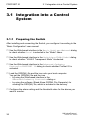
3.1
Integration into a Control System
3.1.1 Preparing the Switch
3.1.2 Configuration of the PLC
3.1.3 Configuring the device
3.1.4 Swapping devices
3.1.5 Swapping modules
3.1.6 Monitoring the network
36
36
37
47
48
49
50
3.2
PROFINET IO Parameters
3.2.1 Alarms
3.2.2 Record parameters
3.2.3 I/O Data
54
54
54
58
4
IEC 61850/MMS (RSR20/RSR30/MACH1000)
61
4.1
Switch model for IEC 61850
62
4.2
Integration into a Control System
4.2.1 Preparing the Switch
4.2.2 Offline configuration
64
64
65
UM IndustProtocol
Release 8.0 05/2013
3
Contents
4.2.3 Monitoring the device
66
A
GSD File Generator
67
B
Readers’ Comments
68
C
Index
71
D
Further Support
73
4
UM IndustProtocol
Release 8.0 05/2013
About this Manual
About this Manual
The “Industry Protocols” user manual describes how the device is connected
by means of a communication protocol commonly used in the industry, such
as EtherNet/IP and PROFINET IO.
The following thematic sequence has proven itself in practice:
Device configuration in line with the “Basic Configuration” user manual
Check on the connection Switch <–> PLC
Program the PLC
The “Installation” user manual contains a device description, safety
instructions, a description of the display, and the other information that you
need to install the device.
The “Redundancy Configuration” user manual document contains the
information you require to select the suitable redundancy procedure and
configure it.
You will find detailed descriptions of how to operate the individual functions
in the “Web-based Interface” and “Command Line Interface” reference
manuals.
The Industrial HiVision Network Management Software provides you with
additional options for smooth configuration and monitoring:
Simultaneous configuration of multiple devices
Graphical user interface with network layout
Auto-topology discovery
Event log
Event handling
Client/server structure
Browser interface
ActiveX control for SCADA integration
SNMP/OPC gateway.
UM IndustProtocol
Release 8.0 05/2013
5
About this Manual
6
UM IndustProtocol
Release 8.0 05/2013
Key
Key
The designations used in this manual have the following meanings:
List
Work step
Subheading
Link
Note:
Cross-reference with link
A note emphasizes an important fact or draws your attention to a dependency.
Courier
ASCII representation in user interface
Symbols used:
WLAN access point
Router with firewall
Switch with firewall
Router
Switch
Bridge
UM IndustProtocol
Release 8.0 05/2013
7
Key
Hub
A random computer
Configuration Computer
Server
PLC Programmable logic
controller
I/O Robot
8
UM IndustProtocol
Release 8.0 05/2013
Industry Protocols
1 Industry Protocols
For a long time, automation communication and office communication were
on different paths. The requirements and the communication properties were
too different.
Office communication moves large quantities of data with low demands with
respect to the transfer time. Automation communication moves small
quantities of data with high demands with respect to the transfer time and
availability.
While the transmission devices in the office are usually kept in temperaturecontrolled, relatively clean rooms, the transmission devices used in
automation are exposed to wider temperature ranges. Dirty, dusty and damp
ambient conditions make additional demands on the quality of the
transmission devices.
With the continued development of communication technology, the demands
and the communication properties have moved closer together. The high
bandwidths now available in Ethernet technology and the protocols they
support enable large quantities to be transferred and exact transfer times to
be defined.
With the creation of the first optical LAN to be active worldwide, at the
University of Stuttgart in 1984, Hirschmann laid the foundation for industrycompatible office communication devices. Thanks to Hirschmann's initiative
with the world's first rail hub in the 1990s, Ethernet transmission devices such
as switches, routers and firewalls are now available for the toughest
automation conditions.
The desire for uniform, continuous communication structures encouraged
many manufacturers of automation devices to come together and use
standards to aid the progress of communication technology in the automation
sector. This is why we now have protocols that enable us to communicate via
Ethernet from the office right down to the field level.
UM IndustProtocol
Release 8.0 05/2013
9
Industry Protocols
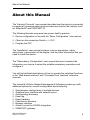
Output
Input
Input
Ethernet
Output
Figure 1: Example of communication.
Hirschmann switches support the following industry protocols and systems
EtherNet/IP
PROFINET IO
Depending on the ordered Industrial Protocol variant the Switch offers the
suitable default settings:
Settings / Variant
Order code
EtherNet/IP
IGMP Snooping
IGMP Querier
Unknown Multicast
Address Conflict Detection
RSTP
DIP switch
100 Mbit/s TP ringports
10
Standard
H
0
0
0
Send To All
Ports
0
1
SW-Konfig
Autoneg
EtherNet/IP
E
1
1
1
Discard
PROFINET IO
P
0
0
0
Discard
1
0
SW-Konfig
Autoneg
0
1
SW-Konfig
Autoneg
UM IndustProtocol
Release 8.0 05/2013
Industry Protocols
Settings / Variant
Static Query Port
Standard
Disable
EtherNet/IP
Automatic
PROFINET IO
Automatic
PROFINET IO
Boot-Modus
VLAN 0 Transparent Modus
HiDiscovery
sysName
0
DHCP
0
Read/Write
Product name
+ 3 Byte MAC
0
DHCP
0
Read/Write
Product name
+ 3 Byte MAC
1
Lokal
1
ReadOnly
empty
If you want to configure a device with the standard configuration for
PROFINET IO, you will find the corresponding dialogs of the WebbasedInterface in the following table.
Parameter
PROFINET IO
Boot Mode
IP Address
Netmask
Gateway Address
VLAN 0 Transparent
HiDiscovery
System Name
Table 1:
Dialog
Advanced:Industrial
Protcols
Basic
Settings:Network/Mode
Basic
Settings:Network/Local
Basic
Settings:Network/Local
Basic
Settings:Network/Local
Switching:VLAN:Global
Action
Activate PROFINET IO.
Select “Local”.
Enter the “IP address” 0.0.0.0.
Enter the “netmask” 0.0.0.0.
Enter the “gateway address”
0.0.0.0.
Activate the “VLAN 0 transparent
mode”.
Basic
Activate the function and select
Settings:Network/HiDisco “Read only” access.
very Protocol
Basic Settings:
Delete the field content.
System/System data
Web-based interface dialogs for setting the PROFINET IO parameters
UM IndustProtocol
Release 8.0 05/2013
11
Industry Protocols
12
UM IndustProtocol
Release 8.0 05/2013
EtherNet/IP
2 EtherNet/IP
EtherNet/IP, which is accepted worldwide, is an industrial communication
protocol standardized by the Open DeviceNet Vendor Association (ODVA)
on the basis of Ethernet. It is based on the widely used transport protocols
TCP/IP and UDP/IP (standard). EtherNet/IP thus provides a wide basis,
supported by leading manufacturers, for effective data communication in the
industry sector.
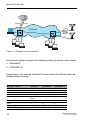
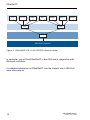
UDP/IP Unicast
UDP/IP Unicast/Multicast
Controller
EtherNet/IP-Stack
Figure 2: Communication between the controller (PLC) and the Switch
EtherNet/IP adds the industry protocol CIP (Common Industrial Protocol) to
the Ethernet as an application level for automation applications. Ethernet is
thus ideally suited to the industrial control technology sector.
UM IndustProtocol
Release 8.0 05/2013
13
EtherNet/IP
FTP
HTTP
DNS
CIP
SNMP
TCP
BOOTP
DHCP
UDP
IP
IEEE 802.3 Ethernet
Figure 3: EtherNet/IP (CIP) in the ISO/OSI reference model
In particular, you will find EtherNet/IP in the USA and in conjunction with
Rockwell controllers.
For detailed information on EtherNet/IP, see the Internet site of ODVA at
www.ethernetip.de.
14
UM IndustProtocol
Release 8.0 05/2013
EtherNet/IP
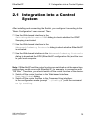
2.1 Integration into a Control System
2.1 Integration into a Control
System
After installing and connecting the Switch, you configure it according to the
“Basic Configuration” user manual. Then:
Use the Web-based interface in the
Switching:Multicasts:IGMP dialog to check whether the IGMP
Snooping is activated.
Use the Web-based interface in the
Advanced:Industry Protocols dialog to check whether EtherNet/IP
is activated.
Use the Web-based interface in the Advanced:Industry Protocols
dialog to download the EDS (EtherNet/IP configuration file) and the icon
to your local computer.
Note: If EtherNet/IP and the router function are switched on at the same time,
malfunctions could occur with EtherNet/IP, for example, in connection with
“RS Who”. Therefore, you should switch off the router function of the device.
Switch off the router function in the Web-based interface:
Routing:Global dialog.
Switch off the router function in the Command Line interface:
in the configuration mode (prompt “..(Config)#”) with the command
no ip routing.
UM IndustProtocol
Release 8.0 05/2013
15
EtherNet/IP
2.1 Integration into a Control System
Configuration of a PLC using the example of Rockwell
software
Open the “EDS Hardware Installation Tool” of RSLinx.
Use the “EDS Hardware Installation Tool” to add the EDS file.
Restart the “RSLinx” service so that RSLinx takes over the EDS file of
the Switch.
Use RSLinx to check whether RSLinx has detected the Switch.
Open your Logix 5000 project.
Integrate the Switch into the Ethernet port of the controller as a new
module (Generic Ethernet Module).
Setting
Comm Format:
IP Address
Input Assembly Instance
Input Size
Output Assembly Instance
Output Size
Configuration Assembly Instance
Configuration Size
Table 2:
16
I/O connection
Data - DINT
Input only
Data - DINT
Listen only
Input data - DINT Run/Program
IP address of the IP address of the IP address of the
Switch
Switch
Switch
2
2
2
7
7
7
(MACH 4000: 11) (MACH 4000: 11) (MACH 4000: 11)
1
254
255
1
0
0
(MACH 4000: 2)
3
3
3
0
0
0
Settings for integrating a Generic Ethernet Module
UM IndustProtocol
Release 8.0 05/2013
EtherNet/IP
2.1 Integration into a Control System
Figure 4: Integrating a new module into Logix 5000
In the module properties, enter a value of at least 100 ms for the
Request Packet Interval (RPI).
Figure 5: Module properties for the Request Packet Interval (RPI)
UM IndustProtocol
Release 8.0 05/2013
17
EtherNet/IP
2.1 Integration into a Control System
Note: If for example, a management program is occupying the Switch
CPU with SNMP requests, the I/O connection between the programmable
logic controller (PLC) and the Switch can be interrupted for a time. As the
Switch can still transmit data packages in this case, the system can also
still be ready for operation.
The monitoring of the I/O connection to the Switch CPU as a failure
criterion can result in system failure and is therefore less suitable as a
failure criterion.
Example of integration from the Sample Code Library
The Sample Code Library is a website from Rockwell. The object of the
website is to provide users with a place where they can exchange their
best architecture integration applications.
On the website http://samplecode.rockwellautomation.com, search for
catalog number 9701. This is the catalog number of an example for
integrating HirschmannSwitches into RS Logix 5000 rel. 16, PLC
firmware release 16.
18
UM IndustProtocol
Release 8.0 05/2013
EtherNet/IP
2.2 EtherNet/IP Parameters
2.2 EtherNet/IP Parameters
2.2.1
Identity Object
The Switch supports the identity object (class code 01) of EtherNet/IP. The
Hirschmann manufacturer ID is 634. Hirschmann uses the manufacturerspecific ID 149 (95H) to indicate the product type “Managed Ethernet Switch”.
ID
Attribute
1
2
Vendor ID
Device Type
Access
Rule
Get
Get
3
Product Code
Get
4
Revision
Get
5
6
Status
Get
Serial Number Get
7
Product Name Get
Table 3:
Data Type
Description
UINT
UINT
Hirschmann 634
Vendor-specific Definition 149 (95H)
“Managed Ethernet Switch”.
UINT
Product Code: mapping is defined for every
device type, e.g.
RS20-0400T1T1SDAPHH is 16650.
STRUCT
Revision of the Ethernet/IP implementation,
USINT Major
currently 1.1,
USINT Minor
Major Revision and Minor Revision
WORD
Not used
UDINT
Serial number of the device (contains last
3 bytes of MAC address).
Short String
Displayed as "Hirschmann" + order code, e.g.
(max. 32 bytes) Hirschmann RSxxxxx.
Identity Object
UM IndustProtocol
Release 8.0 05/2013
19
EtherNet/IP
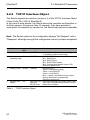
2.2.2
2.2 EtherNet/IP Parameters
TCP/IP Interface Object
The Switch supports an instance (instance 1) of the TCP/IP Interface Object
(Class Code F5H, 245) of EtherNet/IP.
In the case of write access, the Switch stores the complete configuration in
its flash memory. Saving can take 10 seconds. If the save process is
interrupted, for example, by a power cut, the Switch may become inoperable.
Note: The Switch replies to the configuration change "Set Request” with a
"Response” although saving of the configuration has not yet been completed.
Id
Attribute
1
Status
2
Interface
Get
Capability flags
3
Config Control Set/Get
4
Physical Link
Object
Table 4:
20
Access
rule
Get
Get
Data type
Description
DWORD
Interface Status (0: Interface not configured,
1: Interface contains valid config).
DWORD
Bit 0: BOOTP Client,
Bit 1: DNS Client,
Bit 2: DHCP Client,
Bit 3: DHCP-DNS Update,
Bit 4: Configuration settable (within CIP).
Other bits reserved (0).
DWORD
Bits 0 through 3:
Value 0: using stored config,
Value 1: using BOOTP,
Value 2: using DHCP.
Bit 4: 1 device uses DNS for name lookup
(always 0 because not supported)
Other bits reserved (0).
Structure: UINT Path to the Physical Link Objekt, always {20H,
Path size
F6H, 24H, 01H} describing instance 1 of the
EPATH Path
Ethernet Link Object.
TCP/IP Interface Object
UM IndustProtocol
Release 8.0 05/2013
EtherNet/IP
2.2 EtherNet/IP Parameters
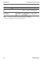
Id
Attribute
Access
rule
Set/Get
5
Interface
Configuration
6
8
9
Host name
Set/Get
TTL Value
Set/Get
Mcast Config
Set/Get
Alloc Control
Reserved
Num Mcast
Mcast Start
Addr
100 Quick Connect Set/Get
Table 4:
Data type
Description
Structure:
UDINT IP
address
UDINT
Netmask
UDINT
Gateway
address UDINT
Name server 1
UDINT Name
server 2
STRING
Domain name
STRING
USINT
STRUCT of:
USINT
IP Stack Configuration (IP-Address, Netmask,
Gateway, 2 Nameservers (DNS, not
supported) and the domain name).
USINT
UINT
UDINT
DWORD
Host name (for DHCP DNS Update).
TTL value for EtherNet/IP multicast packets
IP multicast address configuration
Multicast address allocation control word.
Determines how addresses are allocated.
Reserved for future use
Number of IP multicast addresses to allocate
for EtherNet/IP
Starting multicast address from which to begin
allocation.
Bitmask of 1 bit per port to enable/disable
Quick Connect.
TCP/IP Interface Object
UM IndustProtocol
Release 8.0 05/2013
21
EtherNet/IP
2.2.3
2.2 EtherNet/IP Parameters
Ethernet Link Object
The Switch supports at least one instance (Instance 1; the instance of the
CPU Ethernet interface) of the Ethernet Link Object (Class Code F6H, 246)
of EtherNet/IP.
Id
Data type
Description
1
Access
rule
Interface Speed Get
UDINT
2
Interface Flags Get
DWORD
3
Physical
Address
Interface
Counters
Used interface speed in MBits/s (10, 100,
1000, …). 0 is used when the speed has not
been determined or is invalid because of
detected problems.
Interface Status Flags:
Bit 0: Link State (1: Link up),
Bit 1: 0: Half-Duplex, 1: FullDuplex1,
Bits 2 through 4: Autoneg Status (0: Autoneg
in Progress, 1: Autoneg unsuccessful,
2: unsuccessful but Speed detected,
3: Autoneg success, 4: No Autoneg),
Bit 5: manual configuration requires reset
(always 0 because not needed),
Bit 6: detected hardware error.
MAC address of physical interface.
ARRAY of 6
USINTs
Struct MIB II
InOctets, InUcastPackets, InNUcastPackets,
Counters
InDiscards, InErrors, InUnknownProtos,
Jeweils UDINT OutOctets, OutUcastPackets,
OutNUcastPackets, OutDiscards, OutErrors.
Struct Ethernet Alignment Errors, FCS Errors, Single
MIB Counters Collision, Multiple Collision, SQE Test Errors,
Jeweils UDINT Deferred Transmissions, Late Collisions,
Excessive Collisions, MAC TX Errors, Carrier
Sense Errors, Frame Too Long, MAC RX
Errors.
Struct Control Control Bits:
Bits WORD
Bit 0: Autoneg enable/disable (1: enable),
Forced Iface
Bit 1: Duplex mode (1: full duplex, if Autoneg
Speed UINT
is disabled).
Interface speed in MBits/s: 10, 100,…, if
Autoneg is disabled.
USINT
Value 0: Unknown interface type,
Value 1: The interface is internal,
Value 2: Twisted-pair,
Value 3: Optical fiber.
4
Attribute
Get
Get
5
Media Counters Get
6
Interface
Control
7
Interface Type Get
Table 5:
22
Get/Set
Ethernet Link-Objekt
UM IndustProtocol
Release 8.0 05/2013
EtherNet/IP
Id
2.2 EtherNet/IP Parameters
Attribute
Data type
Description
8
Access
rule
Interface State Get
USINT
9
Admin State
USINT
Value 0: Unknown interface state,
Value 1: The interface is enabled,
Value 2: The interface is disabled,
Value 3: The interface is testing,
Value 1: Enable the interface,
Value 2: Disable the interface.
Interface name. The content of the string is
vendor-specific.
Set
10 Interface Label Get
Table 5:
SHORT_
STRING
Ethernet Link-Objekt
The Switch supports additional vendor specific attributes.
Id
Attribute
Access
rule
Get
100 Ethernet
(64 Interface Index
H)
101 Port Control
Get/Set
(65
H)
102
(66
H)
103
(67
H)
Data type
Description
UDINT
Interface/Port Index (ifIndex from MIB II)
DWORD
Bit 0 (RO): Link state (0: link down, 1: link up)
Bit 1 (R/W): Link admin state (0: disabled,
1: enabled)
Bit 8 (RO:) Access violation alarm
Bit 9 (RO): Utilization alarm
The existing Counter from the private MIB
hmIfaceUtilization is used. Utilization in
percentagea. RX Interface Utilization.
Within this parameter the variable
hmIfaceUtilizationAlarmUpperThreshold can
be accessed.
Utilization in percentagea. RX Interface
Utilization Upper Limit.
Within this parameter the variable
hmIfaceUtilizationAlarmLowerThreshold can
be accessed.
Utilization in percentagea. RX Interface
Utilization Lower Limit.
Interface
Utilization
Get
UDINT
Interface
Utilization
Alarm Upper
Threshold
Get/Set
UDINT
104 Interface
(68 Utilization
H) Alarm Lower
Threshold
Get/Set
UDINT
Table 6:
Hirschmann-Erweiterungen des Ethernet Link-Objekts
UM IndustProtocol
Release 8.0 05/2013
23
EtherNet/IP
Id
Attribute
Access
rule
105 Broadcast Limit Get/Set
(69
H)
106 Ethernet
Get
(6A Interface
H) Description
Table 6:
2.2 EtherNet/IP Parameters
Data type
Description
UDINT
Broadcast limiter Service (Egress BC-Frames
limitation, 0: disabled), Frames/second
STRING
[max. 64 Bytes]
even number of
Bytes
Interface/Port Description
(from MIB II ifDescr), e.g. "Unit: 1 Slot: 2 Port:
1 - 10/100 Mbit TX", or "unavailable",
max. 64 Bytes.
Hirschmann-Erweiterungen des Ethernet Link-Objekts
a. Einheit: 1 Hundertstel von 1%, d.h., 100 entspricht 1%
24
UM IndustProtocol
Release 8.0 05/2013
EtherNet/IP
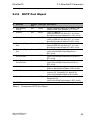
2.2.4
2.2 EtherNet/IP Parameters
Ethernet Switch Agent Object
The Switch supports the Hirschmann vendor specific Ethernet Switch Agent
Object (Class Code 95H, 149) for the Switch configuration and information
parameters with one instance (Instance 1).
For further information on these parameters and how to adjust them refer to
the Reference Manual „GUI“ (Graphical User Interface / Web-based
Interface).
Attribute
Switch Status
ID/Bit No.
ID 01
Bit 0
Bit 1
Bit 2
Bit 3
Bit 4
Bit 5
Bit 6
Bit 7
Bit 8
Bit 9
Bit 10
Bit 11
Bit 12
Bit 13
Bit 16
Bit 17
Bit 21
Bit 22
Bit 23
Bit 24
Bit 25
Bit 28
Bit 29
Table 7:
Description
DWORD (32 bit) RO
Overall state (0: ok, 1: failed) Like the signal contact.
Power Supply 1 (0: ok, 1: failed or does not exist)
Power Supply 2 (0: ok, 1: failed or does not exist)
Power Supply 3 (0: ok or not possible on this platform, 1: failed
or does not exist)
Power Supply 4 (0: ok or not possible on this platform, 1: failed
or does not exist)
Power Supply 5 (0: ok or not possible on this platform, 1: failed
or does not exist)
Power Supply 6 (0: ok or not possible on this platform, 1: failed
or does not exist)
Power Supply 7 (0: ok or not possible on this platform,
1: failed or does not exist)
Power Supply 8 (0: ok or not possible on this platform,
1: failed or does not exist)
DIP RM (ON: 1, OFF: 0)
DIP Standby (ON: 1, OFF: 0)
Signal Contact 1 (0: closed, 1: open)
Signal Contact 2 (0: closed, 1: open)
Quick Connect (1: ON, 0: OFF)
Temperature (0: ok, 1: threshold exceeded)
Fan (0: ok or no fan, 1: inoperable)
DIP Ring ports, 0: module 1 ports 1&2, 1: module 2, ports 1&2
DIP Configuration (1: enabled, 0: disabled)
DIP HIPER-Ring state (1: ON, 0: OFF)
Module removed (1: removed)
ACA removed (1: removed)
Hiper-Ring (1: loss of redundancy reserve)
Ring-/Netcoupling (1: loss of redundancy reserve)
Hirschmann Ethernet Switch Agent Object
UM IndustProtocol
Release 8.0 05/2013
25
EtherNet/IP
Attribute
2.2 EtherNet/IP Parameters
ID/Bit No.
Bit 30
ID 02
Switch
Temperature
Reserved
ID 03
Switch Max
ID 04
Ports
Multicast
ID 05
Settings (IGMP
Snooping)
Bit 0 RW
Bit 1 RW
Bit 2 RO
Bit 4-6 RW
Bit 8-10 RW
Switch Existing ID 06
Ports
Per Bit starting
with Bit 0
(means Port 1)
Switch Port
ID 07
Control
Per Bit starting
with Bit 0
(means Port 1)
Switch Ports
Mapping
Switch Action
Status
Always 0, attribute is reserved for future use.
UINT (16 bit) RO Maximum number of Ethernet Switch Ports
WORD (16 bit) RW
IGMP Snooping (1: enabled, 0: disabled)
IGMP Querier (1: enabled, 0: disabled)
IGMP Querier Mode (1: Querier, 0: Non-Querier)
IGMP Querier Packet Version 1: V1, 2: V2, 3: V3, 0: Off (IGMP
Querier disabled)
Treatment of Unknown Multicasts (Railswitch only): 0: Send To
All Ports, 1: Send To Query Ports, 2: Discard
ARRAY OF DWORDa RO Bitmask of existing Switch Ports
1: Port existing, 0: Port not available. Array (bit mask) size is
adjusted to the size of maximum number of Switch ports (e.g.
a max. no of 28 ports means that 1 DWORD is used (32 bit)).
ARRAY OF DWORDa RW Bitmask Link Admin Status Switch
Ports
0: Port enabled, 1: Port disabled. Array (bit mask) size is
adjusted to the size of maximum number of Switch ports
(e.g. a max. no of 28 ports means that 1 DWORD is used (32
bit)).
ID 08
ARRAY OF USINT (BYTE, 8 bit) RO Instance number of the
Ethernet Link Object
All Ethernet Link Object Instances for the existing Ethernet
Starting with
Index 0
Switch Ports (1..N (maximum number of ports)). When the
(means Port 1) entry is 0, the Ethernet Link Object for this port does not exist.
ID 09
DWORD (32 bit) RO
Bit 0
Bit 1
Table 7:
Description
Connection Error (1: link inoperable)
Struct{INT RO Temperature °F, INT RO Temperature °C}
Flash write in progress
Unable to write to flash or write incomplete
Hirschmann Ethernet Switch Agent Object
a. RS20/RS30/RS40, MS20/MS30, OCTOPUS, PowerMICE, RSR20/RSR30, MACH 100 and
MACH 1000: 32 bit;
MACH 4000: 64 bit
26
UM IndustProtocol
Release 8.0 05/2013
EtherNet/IP
2.2 EtherNet/IP Parameters
The Hirschmann specific Ethernet Switch Agent Object provides you with the
additional vendor specific service, with the Service-Code 35H for saving the
Switch configuration. The Switch replies to the request for saving the
configuration, as soon as it saved the configuration in the flash memory.
UM IndustProtocol
Release 8.0 05/2013
27
EtherNet/IP
2.2.5
Id
2.2 EtherNet/IP Parameters
RSTP Bridge Object
Attribute
Access Data type Description
rule
1
Bridge Identifier
Set
UDINT
Range: 0 to 61,440 in steps of 4,096, default:
Priority
32,768
(refer to IEEE, 802.1D-2004, § 17.13.7)
2
Transmit Hold
Set
UINT
Range: 1 to 40, default: 10
Count
(refer to IEEE 802.1D-2004, §17.13.12)
3
Force Protocol
Set
UINT
Default:2
Version
(refer to IEEE 802.1D-2004, §17.13.4 and
dot1dStpVersion in RFC 4318)
4
Bridge Hello Time Set
UDINT
Range: 100 to 200, unit: centi-seconds (1/100 of
a second), default: 200
(refer to IEEE 802.1D-2004, §17.13.6 and
dot1dStpHoldTime in RFC 4188)
5
Bridge Forward
Set
UDINT
Range: 400 to 3000, unit: centi-seconds, default:
Delay
2100
(refer to IEEE 802.1D-2004, §17.13.5 and
dot1dStpForwardDelay in RFC 4188)
6
Bridge Max. Age Set
UINT
Range: 600 to 4000, unit: centi-seconds, default:
4000
(refer to IEEE 802.1D-2004, §17.13.8 and
dot1dStpBridgeMaxAge in RFC 4188)
7
Time Since
Get
UDINT
Unit: centi-seconds
Topology Change
(refer to dot1dStpTimeSinceTopologyChange in
RFC 4188)
8
Topology Change Get
UDINT
Refer to dot1dStpTopChanges in RFC 4188
100 InnerPort
Get
UINT
Hirschmann-specific object.
For instance 1, it holds the port number of the
DRSTP Primary instance‘s inner port.
For instance 2, it holds the port number of the
DRSTP Secondary instance‘s inner port.
101 OuterPort
Get
UINT
Hirschmann-specific object.
For instance 1, it holds the port number of the
DRSTP Primary instance‘s outer port.
For instance 2, it holds the port number of the
DRSTP Secondary instance‘s outer port.
Table 8:
28
Hirschmann RSTP Bridge Object
UM IndustProtocol
Release 8.0 05/2013
EtherNet/IP
2.2.6
RSTP Port Object
Id
Attribute
1
2
Port Identifier
Priority
mcheck
3
Port Path Cost
4
Port Admin Edge
Port
5
Port Oper Edge
Port
6
Port Admin
PointToPoint
7
Port Oper
PointToPoint
8
Port Enable
9
Port State
10 Port Role
100 DRSTP
Table 9:
2.2 EtherNet/IP Parameters
Access Data type Description
rule
Set
UDINT
Range: 0 to 240 in steps of 16, default: 128
(refer to IEEE, 802.1D-2004, § 17.13.10).
Set
BOOL
True (1), False (2)
(refer to IEEE 802.1D-2004, §17.19.13 and
dot1dStpPortProtocolMigration in RFC 4318).
Set
UDINT
Range: 1 to 200,00,000, default:auto (0)
(refer to IEEE 802.1D-2004, §17.13.11 and
dot1dStpPortAdminPathCost in RFC 4318).
Set
BOOL
True (1), False (2)
(refer to IEEE 802.1D-2004, §17.13.1 and
dot1dStpPortAdminEdgePort in RFC 4318).
Get
BOOL
True (1), False (2)
(refer to dot1dStpPortOperEdgePort in
RFC 4318).
Set
UINT
forceTrue (0), forceFalse (1), auto (2)
(refer to dot1dStpPortAdminPointToPoint in
RFC 4318).
Get
UINT
True (1), False (2)
(refer to dot1dStpPortOperPointToPoint in
RFC 4318).
Set
UINT
Enabled (1), Disabled (2)
(Refer to dot1dStpPortEnable in RFC 4188).
Get
UINT
Disabled (1), Blocking (2), Listening (3),
Learning (4), Forwarding (5), Broken (6)
(refer to dot1dStpPortState in RFC 4188).
Get
UNT
Unknown (0), Alternate/Backup (1), Root (2),
Designated (3)
(refer to dot1dStpTopChanges in RFC 4188).
Get
UINT
Hirschmann-specific object. True (1), False (2).
Hirschmann RSTP Port Object
UM IndustProtocol
Release 8.0 05/2013
29
EtherNet/IP
2.2.7
2.2 EtherNet/IP Parameters
I/O Data
You will find the exact meaning of the individual bits of the device status in
the I/O data in “Ethernet Switch Agent Object” on page 25.
I/O Data
Device Status
Link Status
Value (data types and sizes to be defined)
Bitmask (see Switch Agent Attribute 1)
Bitmask, 1 Bit per port
0: No link, 1: Link up
Output Links
Bitmask (1 Bit per port) to acknowledge output.
Admin State
Link state change can be denied, e.g. for controller
applied
access port.
0: Port enabled, 1: Port disabled.
Utilization Alarm Bitmask, 1 Bit per port
0: No alarm, 1: Alarm on port
Access Violation Bitmask, 1 Bit per port
Alarm
0: No alarm, 1: Alarm on port
Multicast
Integer, number of connections
Connections
TCP/IP
Integer, number of connections
Connections
Link Admin State Bitmask, one bit per port
0: Port enabled, 1: Port disabled
Direction
Input, DWORD 32 Bit
Input, DWORDa
Input DWORDa
Input, DWORDa
Input, DWORDa
Input, 1 DINT 32 bit
Input, 1 DINT 32 bit
Output, DWORDa
Table 10: I/O Data
a. RS20/RS30/RS40, MS20/MS30, OCTOPUS, PowerMICE, RSR20/RSR30, MACH 100 and
MACH 1000: 32 Bit;
MACH 4000: 64 Bit
30
UM IndustProtocol
Release 8.0 05/2013
EtherNet/IP
2.2.8
2.2 EtherNet/IP Parameters
Assignment of the Ethernet Link Object
Instances
The table shows the assignment of the Switch ports to the Ethernet Link
Object Instances.
Ethernet Link
Object Instance
1
2
3
4
5
6
7
8
9
10
11
12
13
14
..
RS20/RS30/RS40
RSR20/RSR30,
OCTOPUS,
MACH 1000
CPU
1
2
3
4
5
6
7
8
9
10
11
12
13
..
MS20/MS30,
PowerMICE,
MACH 100
MACH 4000
CPU
Module 1 / port 1
Module 1 / port 2
Module 1 / port 3
Module 1 / port 4
Module 2 / port 1
Module 2 / port 2
Module 2 / port 3
Module 2 / port 4
Module 3 / port 1
Module 3 / port 2
Module 3 / port 3
Module 3 / port 4
Module 4 / port 1
..
CPU
Module 1 / port 1
Module 1 / port 2
Module 1 / port 3
Module 1 / port 4
Module 1 / port 5
Module 1 / port 6
Module 1 / port 7
Module 1 / port 8
Module 2 / port 1
Module 2 / port 2
Module 2 / port 3
Module 2 / port 4
Module 2 / port 5
..
Table 11: Assignment of the Switch ports to the Ethernet Link Object Instances
UM IndustProtocol
Release 8.0 05/2013
31
EtherNet/IP
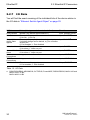
2.2.9
2.2 EtherNet/IP Parameters
Supported Services
The table gives you an overview of the services for the object instances
supported by the EtherNet/IP implementation.
Service code
Identity Object TCP/IP
Interface
Object
Get Attribute All All Attributes
All Attributes
(01H)
Set Attribute All Settable
(02H)
Attributes (3, 5,
6)
Get Attribute
All Attributes
All Attributes
Single (0EH)
Set Attribute
Settable
Single (10H)
Attributes (3, 5,
6)
Reset (05H)
Save
Configuration
(35H) Vendorspecific
Parameter (0.1) Parameter (0.1) -
Ethernet Link
Object
Switch Agent
Object
All Attributes
All Attributes
-
-
All Attributes
All Attributes
Settable
Attributes (6,
65H, 67H, 68H,
69H)
-
Settable
Attributes (7)
Save Switch
Configuration
Table 12: Supported Services
32
UM IndustProtocol
Release 8.0 05/2013
PROFINET IO
3 PROFINET IO
PROFINET IO is an industrial communication network based on Ethernet
that is accepted worldwide. It is based on the widely used transport protocols
TCP/IP and UDP/IP (standard). This is an important aspect for fulfilling the
requirements for consistency from the management level down to the field
level.
PROFINET IO enhances the existing Profibus technology for such
applications that require fast data communication and the use of industrial IT
functions.
DCP (Discovery and Configuration Protocol)
Alarm High, Alarm Low
ARP, UDP/IP Unicast
Controller
ARP, UDP/IP Unicast
Alarm High, Alarm Low
Profinet IO-Stack
PNIO (Profinet IO cyclic TR Frame)
DCP (Discovery and Configuration Protocol)
Figure 6: Communication between the Controller and the Switch
In particular, you will find PROFINET IO in Europe and in conjunction with
Siemens controllers.
PROFINET IO uses the device description language GSDML (Generic
Station Description Markup Language) to describe devices and their
properties so that they can be processed automatically. You will find the
device description in the GSD(ML) file of the device.
You will find detailed information on PROFINET on the Internet site of the
PROFIBUS Organization at http://www.profibus.com.
The devices conform to class B for PROFINET IO.
UM IndustProtocol
Release 8.0 05/2013
33
PROFINET IO
Switch Models for PROFINET IO GSDML Version 1.0
Bus Interface
Slot 0
Slot 1
Slot 2
Slot 3
Slot 4
Port 1
Port 2
Port 3
Port 4
Compact
Figure 7: Compact Switch
Bus Interface
Slot 0
Slot 1
Slot 2
Module 1
Module 2
Port 1
Record 1
Port 2
Record2
Port 1
Record 1
Port 2
Record2
Modular
Figure 8: Modular Switch
34
UM IndustProtocol
Release 8.0 05/2013
PROFINET IO
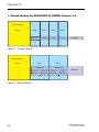
Switch Models for PROFINET IO GSDML Version 2.0
Bus Interface
Slot 0
Compact
SubSl
0x8001
SubSl
0x8002
SubSl
0x8003
SubSl
0x8004
SubSl
0x8005
SubSl
0x8006
Port 1
Port 2
Port 3
Port 4
Port 5
Port 6
SubSl =Subslot
Figure 9: Compact Switch
Bus Interface
Slot 0
Slot 1
Slot 2
Module 1
Module 2
SubSl SubSl SubSl SubSl SubSl SubSl SubSl SubSl
0x
0x
0x
0x
0x
0x
0x
0x
8001 8002 80.. 80.n 8001 8002 80.. 80.n
Modular
SubSl =
Subslot
Port 1 Port 2 Port .. Port n Port 1 Port 2 Port .. Port n
Figure 10: Modular Switch
UM IndustProtocol
Release 8.0 05/2013
35
PROFINET IO
3.1 Integration into a Control System
3.1 Integration into a Control
System
3.1.1
Preparing the Switch
After installing and connecting the Switch, you configure it according to the
“Basic Configuration” user manual:
Use the Web-based interface in the Basic Settings:Network dialog
to check whether Local is selected in the “Mode” frame.
Use the Web-based interface in the Switching:VLAN:Global dialog
to check whether “VLAN 0 Transparent Mode” is selected.
Use the Web-based interface in the Advanced:Industry
Protocols:PROFINET IO dialog to check whether Profinet IO is
activated.
Load the GSD(ML) file and the icon onto your local computer.
You get the GSD(ML) file and the icon
– by using the Web-based interface in the
Advanced:Industry Protocols dialog or
– by using the software (Stand Alone GSDML File Generator) for
creating the GSD(ML) file, which is included in the delivery.
Configure the alarm setting and the threshold value for the alarms you
want to monitor.
36
UM IndustProtocol
Release 8.0 05/2013
PROFINET IO
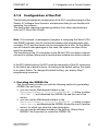
3.1.2
3.1 Integration into a Control System
Configuration of the PLC
The following illustrates the configuration of the PLC using the example of the
Simatic S7 software from Siemens, and assumes that you are familiar with
operating the software.
The device also supports engineering stations from other manufacturers,
such as PC Worx from Phönix.
Note: If for example, a management program is occupying the Switch CPU
with SNMP requests, the I/O connection between the programmable logic
controller (PLC) and the Switch can be interrupted for a time. As the Switch
can still transmit data packages in this case, the system can also still be
ready for operation.
The monitoring of the I/O connection to the Switch CPU as a failure criterion
can result in system failure and is therefore less suitable as a failure criterion.
In the PLC default setting, the PLC sees the interruption of the I/O connection
to the Switch as a failure criterion. According to the default setting, this leads
to a system failure. To change this default setting, you employ Step7
programming measures.
Providing the GDSML file
The Hirschmann provides you with the following options for generating
GDSML files and icons:
you can use the Web-based interface in the
Advanced:Industry Protocols:PROFINET IO dialog to select
PROFINET IO and download the GSDML file and the icon of the
device.
you can use the Web-based interface in the
Advanced:Industry Protocols:PROFINET IO dialog to select
Other device and download the GSDML file and the icon of another
device, for which you enter the order description.
you can use the software included in the delivery (Stand Alone
GSDML File Generator) to create the GSDML file.
UM IndustProtocol
Release 8.0 05/2013
37
PROFINET IO
3.1 Integration into a Control System
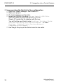
Incorporating the Switch in the configuration
Open the “Simatic Manager” from Simatic S7.
Open your project.
Go to the hardware configuration.
Install the GSD(ML) file using Extras:Install GSD File.
Select the GSD file previously saved on your PC.
Simatic S7 installs the file together with the icon.
You will find the new Switch under Profinet IO:Other Field
Devices:Switching Devices:Hirschmann.. or under
Profinet IO:Other Field Devices:Network
Components:Hirschmann...
Use Drag & Drop to pull the Switch onto the bus cable.
38
UM IndustProtocol
Release 8.0 05/2013
PROFINET IO
3.1 Integration into a Control System
Figure 11: Adding a Switch from the Simatic S7 library
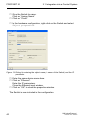
To give the Switch its name, select the Switch and in the menu bar
choose Target System:Ethernet:Edit Ethernet
Participants...
Figure 12: Dialog for entering the Switch name
Click on “Browse”.
Select your Switch.
Click on “OK”.
UM IndustProtocol
Release 8.0 05/2013
39
PROFINET IO
3.1 Integration into a Control System
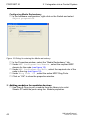
Give the Switch its name.
Click on “Assign Name”.
Click on “Close”.
In the hardware configuration, right-click on the Switch and select
Object properties.
Figure 13: Dialog for entering the object name (= name of the Switch) and the IP
parameter
Enter the same device name here.
Click on “Ethernet”.
Enter the IP parameters.
Close the Ethernet input window.
Click on “OK” to close the properties window.
The Switch is now included in the configuration.
40
UM IndustProtocol
Release 8.0 05/2013
PROFINET IO
3.1 Integration into a Control System
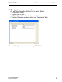
Configuring IO Cycle
In the hardware configuration, right-click on the Switch and select
Object properties.
Figure 14: Dialog for entering the IO Cycle
In the Properties window, select the “IO Cycle” tab.
Under Update Time/Update time[ms]:, select the required
update time (in ms) for the IO Cycle (see figure 14).
Under Watchdog Time/Number of accepted update cycles
with missing IO data , select the required number for the IO
Cycle (see figure 14).
Click on “OK” to close the properties window.
UM IndustProtocol
Release 8.0 05/2013
41
PROFINET IO
3.1 Integration into a Control System
Configuring Media Redundancy
In the hardware configuration, right-click on the Switch and select
Object properties.
Figure 15: Dialog for entering the Media redundancy
In the Properties window, select the “Media Redundancy” tab.
Under MRP Configuration/Domain , select the required MRP
domain for the node (see figure 15).
Under MRP Configuration/Role , select the required role of the
node in the ring (see figure 15).
Under Ring Port 1/2 , select the actice MRP Ring Ports.
Click on “OK” to close the properties window.
Adding modules for modular devices
Use Drag & Drop to pull a module from the library into a slot.
Simatic S7 adds the ports using the Module properties.
42
UM IndustProtocol
Release 8.0 05/2013
PROFINET IO
3.1 Integration into a Control System
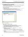
Configuring device property
On slot 0 you enter the settings for the entire Switch.
Select the Switch.
Right-click on slot 0.
To configure the entire device, select Object properties.
In the Properties window, select the “Parameters” tab.
Figure 16: Configuring device alarms for e.g. RS20/RS30.
UM IndustProtocol
Release 8.0 05/2013
43
PROFINET IO
3.1 Integration into a Control System
Configuring the port properties
For modular devices, slots 1 to n represent the modules. Within the slots,
the ports are shown as records.
For non-modular devices, the slots 1 to n represent the ports.
Configuring Alarms
Right-click on one of the slots 1 to n and select Object properties.
In the Properties window, select the “Parameters” tab.
Select the desired alarms and close the window (see figure 17).
Figure 17: Port properties
Special case: “LinkDown” alarm:
The LinkDown alarm is made up of the AND-link
– of the Hirschmann-specific status for connection errors and
– of the Simatic S7-specific option for the connection.
Activating the LinkDown alarm:
Under Object properties, select the Parameter tab
(Hirschmann-specific).
Activate “Alarms” and select the option Generate diagnosis
alarm when link goes down under “Link state monitoring”.
Under Object properties, select the Options tab (Simatic S7specific).
To activate the link monitoring, select a fixed setting for the port under
Connection/Transmission medium/Duplex.
44
UM IndustProtocol
Release 8.0 05/2013
PROFINET IO
3.1 Integration into a Control System
Configuring Connection Options
Right-click on one of the slots 1 to n and select Object
properties.
Figure 18: Dialog for entering the connection options
In the Properties window, select the "Options" tab.
Under Connection/Transmission medium/duplex, select the
required setting for the port (see figure 18).
Click on “OK” to close the properties window.
UM IndustProtocol
Release 8.0 05/2013
45
PROFINET IO
3.1 Integration into a Control System
Configuring Topology
Right-click on one of the slots 1 to n and select Object
properties.
Figure 19: Dialog for entering the topology
In the Properties window, select the "Topology" tab.
Under Port Interconnection/Local port, select the required
setting for the port (see figure 19).
Under Partner/Partner port, select the required setting for the
partner port (see figure 19).
Click on “OK” to close the properties window.
46
UM IndustProtocol
Release 8.0 05/2013
PROFINET IO
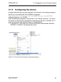
3.1.3
3.1 Integration into a Control System
Configuring the device
Included with the device is the program “Hirschmann Tool Calling Interface”,
which you can install with the installation program
HirschmannToolCallingInterfaceXXXXXSetup.exe (XXXXX =
software version, e.g. 01000).
After installing the program “Hirschmann Tool Calling Interface”, you have
the option of starting two Hirschmann operating programs in Simatic S7 in
order to perform more detailed device configurations.
In Simatic S7, right-click on a device and select Web-based Interface
(WWW) or Telnet in the drop-down menu.
Figure 20: Call up the Hirschmann operating program
UM IndustProtocol
Release 8.0 05/2013
47
PROFINET IO
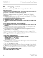
3.1.4
3.1 Integration into a Control System
Swapping devices
Hirschmann devices support the device swapping function with an
engineering station.
If identical devices are being swapped, the engineering station assigns the
parameters of the original device to the new device.
The device swapping function with Simatic S7 requires the following
prerequisites:
S7 300 with SW release from V2.7 (currently available for CPU 319) or
S7 400 with SW release from V5.2
Hirschmann device SW release from 05.0.00
Neighboring device(s) support(s) LLDP
Topology (=neighborhood relationships) is configured and loaded onto
SPS
Device swapping requires the following conditions:
the replacement device is of exactly the same type as the device to be
replaced.
the replacement device is connected to exactly the same place in the
network (same ports and neighboring devices).
the replacement device has a Profinet default configuration. Set the
device name to "" (null string).
If all these conditions are fulfilled, the engineering station automatically
assigns the parameters of the original device (device name, IP parameters
and configuration data) to the replacement device.
Procedure for swapping devices:
Reset the replacement device to the state on delivery:
- System name "" (= null string)
- IP address = 0.0.0.0 or DHCP
- PROFINET IO activated
Make a note of the port assignment of the original device and remove the
original device from the system.
The PLC now detects an error.
Now insert the replacement device at the same position in the network.
Make sure the port assignments are the same as for the original device.
The PLC finds the replacement device and configures it like the original
device.
The PLC detects normal operation again.
If necessary, reset the PLC to “Run”.
48
UM IndustProtocol
Release 8.0 05/2013
PROFINET IO
3.1.5
3.1 Integration into a Control System
Swapping modules
The PROFINET IO stack in the device detects a change in the modules
connected and reports the change to the engineering station. If a previously
configured module is removed from the device, the engineering station
reports an error. If a configured module that was missing is connected, the
engineering station removes the error message.
UM IndustProtocol
Release 8.0 05/2013
49
PROFINET IO
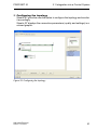
3.1.6
3.1 Integration into a Control System
Monitoring the network
Topology Discovery
After the user initializes the Topology Discovery, the engineering station
looks for connected devices.
Figure 21: Topology Discovery
50
UM IndustProtocol
Release 8.0 05/2013
PROFINET IO
3.1 Integration into a Control System
Configuring the topology
Simatic S7 gives the user the option to configure the topology and monitor
it accordingly.
Simatic S7 displays the connection parameters (quality and settings) in a
colored graphic.
Figure 22: Configuring the topology
UM IndustProtocol
Release 8.0 05/2013
51
PROFINET IO
3.1 Integration into a Control System
Communication diagnosis
Simatic S7 monitors the communication quality and outputs messages
relating to communication problems.
Figure 23: Diagnosis messages for the communication between the Switches and
IO devices
52
UM IndustProtocol
Release 8.0 05/2013
PROFINET IO
3.1 Integration into a Control System
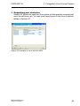
Outputting port statistics
Simatic S7 counts for each port the number of data packets received and
sent, the collisions, etc. You can view these figures in the form of statistic
tables in Simatic S7.
Figure 24: Example of a port statistic table
UM IndustProtocol
Release 8.0 05/2013
53
PROFINET IO
3.2 PROFINET IO Parameters
3.2 PROFINET IO Parameters
3.2.1
Alarms
The Switch supports alarms on the device and port levels (see „Device State“
in the Basic Configuration User Manual or the Web-based Interface
Reference Manual.
Alarms on device level
Alarms on port level
Change in device status - Failure of redundant power
supply - Failure/removal of ACA
- Change in link status - Specified transfer rate exceeded.
Table 13: Alarms supported
3.2.2
Record parameters
The Switch provides records for:
Device parameters
Device status
Port status/parameters
54
UM IndustProtocol
Release 8.0 05/2013
PROFINET IO
Byte
Content
0
Send alarm if status
changes
1
Power Alarm
2
ACA Alarm
3
Module Alarm
3.2 PROFINET IO Parameters
Acces Value Meaning
s
rw
0
Do not send alarms
1
Send alarm if one of the following alarm
reasons occurs.
rw
0
Do not send alarm
1
Send alarm if a power supply fails.
rw
0
Do not send alarm
1
Send alarm if the ACA is removed.
rw
0
Do not send alarm
1
Send alarm if the module connections are
changed.
Table 14: Device parameters
Byte
Content
0
Device Status
1
Power supply unit 1
2
Power supply unit 2
3
Power supply unit 3
4
Power supply unit 4
5
Power supply unit 5
6
Power supply unit 6
7
Power supply unit 7
Acces Value Meaning
s
ro
0
Unavailable
1
OK
2
Error
ro
0
Unavailable
1
OK
2
Error
ro
0
Unavailable
1
OK
2
Error
ro
0
Unavailable
1
OK
2
Error
ro
0
Unavailable
1
OK
2
Error
ro
0
Unavailable
1
OK
2
Error
ro
0
Unavailable
1
OK
2
Error
ro
0
Unavailable
1
OK
2
Error
Table 15: Device status
UM IndustProtocol
Release 8.0 05/2013
55
PROFINET IO
Byte
8
9
10
11
12
13
14
15
16
17
3.2 PROFINET IO Parameters
Content
Acces Value Meaning
s
Power supply unit 8
ro
0
Unavailable
1
OK
2
Error
Signal contact 1
ro
0
Unavailable
1
Closed
2
Open
Signal contact 2
ro
0
Unavailable
1
Closed
2
Open
Temperature
ro
0
Unavailable
1
OK
2
Threshold value for temperature exceeded or
not reached
Fan
ro
0
Unavailable
1
OK
2
Fan failure
Module removal
ro
0
Unavailable
1
OK
2
A module has been removed.
ACA removal
ro
0
Unavailable
1
OK
2
The ACA has been removed.
HIPER_Ring
ro
0
Unavailable
1
OK
2
Redundancy failure.
Ring/Network coupling ro
0
Unavailable
1
OK
2
Redundancy failure.
Connection
ro
0
Unavailable
1
OK
2
Connection failure.
Table 15: Device status
Byte
Content
0
Report port error
Acces Value Meaning
s
rw
0
Do not send alarms
1
Send alarm if one of the following alarm
reasons occurs.
Table 16: Port status/parameters
56
UM IndustProtocol
Release 8.0 05/2013
PROFINET IO
Byte
Content
1
Report connection
error
2
Transmission rate too
high
3
Port on
4
Link status
5
Bit rate
6
Duplex
3.2 PROFINET IO Parameters
Acces Value Meaning
s
rw
0
Do not send alarm
1
Send alarm if the connection has failed.
rw
0
Do not send alarm
1
Send alarm if the threshold value for the
temperature has been exceeded.
rw
0
Unavailable
1
Switched on
2
Switched off
ro
0
Unavailable
1
Connection exists
2
Connection interrupted
ro
0
Unavailable
1
Unknown
2
10 MBit/s
2
100 MBit/s
2
1000 MBit/s
ro
0
Unavailable
1
2
7
Autonegotiation
ro
Half
duplex
Full
duplex
0
Unavailable
1
Off
2
On
Table 16: Port status/parameters
UM IndustProtocol
Release 8.0 05/2013
57
PROFINET IO
3.2.3
3.2 PROFINET IO Parameters
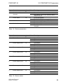
I/O Data
You will find the bit assignment for the transferred I/O data in the following
table.
Direction
Input
Byte
0
Bit
0
1
2
3
4
5
6
7
Input
1
0
1
2
3
4
5
6
7
Input
2
0
1
2
3
4
5
6
7
Output
Meaning of the bit content:
- 0: OK or unavailable
- 1: Reason for report exists
Meaning
General
Device status
Signal contact 1
Signal contact 2
Temperature
Fan
Module removal
ACA removal
Not used
Power supply status
Power supply unit 1
Power supply unit 2
Power supply unit 3
Power supply unit 4
Power supply unit 5
Power supply unit 6
Power supply unit 7
Power supply unit 8
Supply voltage status
HIPER-Ring
Ring/Network coupling
Connection error
Not used
Not used
Not used
Not used
Not used
Not defined
Table 17: Device I/O data
58
UM IndustProtocol
Release 8.0 05/2013
PROFINET IO
Direction
Input
Byte
0
3.2 PROFINET IO Parameters
Bit
0
1
2
3
4
5
6
7
Input
1
0
1
2
3
4
5
6
7
Input
n
0
1
2
3
4
5
6
7
Meaning of the bit content:
- 0: no connection
- 1: connection active
Output
0
0
1
2
3
4
5
6
7
Meaning
Connection status for ports 1 to 8
Port 1
Port 2
Port 3
Port 4
Port 5
Port 6
Port 7
Port 8
Connection status for ports 9 to 16
Port 9
Port 10
Port 11
Port 12
Port 13
Port 14
Port 15
Port 16
Connection for port (n * 8) + 1 to port (n * 8) + 8
Port (n * 8) + 1
Port (n * 8) + 2
Port (n * 8) + 3
Port (n * 8) + 4
Port (n * 8) + 5
Port (n * 8) + 6
Port (n * 8) + 7
Port (n * 8) + 8
“Port activated” for ports 1 to 8
Port 1 activated
Port 2 activated
Port 3 activated
Port 4 activated
Port 5 activated
Port 6 activated
Port 7 activated
Port 8 activated
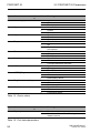
Table 18: Port I/O data
UM IndustProtocol
Release 8.0 05/2013
59
PROFINET IO
Direction
Output
Byte
1
3.2 PROFINET IO Parameters
Bit
0
1
2
3
4
5
6
7
Output
Meaning
“Port activated” for ports 9 to 16
Port 9 activated
Port 10 activated
Port 11 activated
Port 12 activated
Port 13 activated
Port 14 activated
Port 15 activated
Port 16 activated
n
“Port activated” for port (n * 8) + 1 to port (n * 8) + 8
0
Port (n * 8) + 1 activated
1
Port (n * 8) + 2 activated
2
Port (n * 8) + 3 activated
3
Port (n * 8) + 4 activated
4
Port (n * 8) + 5 activated
5
Port (n * 8) + 6 activated
6
Port (n * 8) + 7 activated
7
Port (n * 8) + 8 activated
Meaning of the output bit content:
- 0: Port activated
- 1: Port deactivated
Table 18: Port I/O data
60
UM IndustProtocol
Release 8.0 05/2013
IEC 61850/MMS
(RSR20/RSR30/MACH1000)
4 IEC 61850/MMS
(RSR20/RSR30/MACH1000)
IEC 61850/MMS is an industrial communication protocol standardized by the
International Electrotechnical Commission (IEC). The protocol is to be found
in substation automation, e.g. in the control technology of energy suppliers.
This protocol, which works in a packet-oriented way, is based on the TCP/IP
transport protocol and uses the Manufacturing Messaging Specification
(MMS) for the client-server communication. The protocol is object-oriented
and defines a standardized configuration language that comprises, among
other things, functions for SCADA, Intelligent Electronic Devices (IED) and
for the network control technology.
Part 6 of the IEC 61850 standard defines the configuration language SCL
(Substation Configuration Language). SCL describes the properties of the
device and the system structure in an automatically processable form. The
properties of the device described with SCL are stored in the ICD file on the
device.
UM IndustProtocol
Release 8.0 05/2013
61
IEC 61850/MMS
(RSR20/RSR30/MACH1000)
4.1 Switch model for IEC 61850
4.1 Switch model for IEC 61850
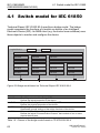
Technical Report IEC 61850 90-4 specifies a bridge model. The bridge
model represents the functions of a switch as objects of an Intelligent
Electronic Device (IED). An MMS client (e.g. the control room software) uses
these objects to monitor and configure the device.
Physical Device
Logical Device
LN LPN0
LN LPHD
LN LBRI
LN LCCH
LN LCCH
LN LCCH
LN LCCF
LN LCCF
LN LCCF
LN LBSP
LN LBSP
LN LBSP
LN LBSP
LN LPLD
LN LPLD
LN LPLD
LN LPLD
LN LPCP
LN LPCP
LN LPCP
LN LPCP
A
Port Number 1
2
paired redundant ports
3
B
4
Figure 25: Bridge model based on Technical Report IEC 61850 90-4
Class
LN LLN0
LN LPHD
LN LBRI
LN LCCH
Description
“Zero” logical node of the “Bridge” IED:
Defines the logical properties of the device.
“Physical Device” logical node of the “Bridge” IED:
Defines the physical properties of the device.
“Bridge” logical node:
Represents general settings of the bridge functions of the device.
“Communication Channel” logical node:
Defines the logical “Communication Channel” that consists of one or more
physical device ports.
Table 19: Classes of the bridge model based on TR IEC61850 90-4
62
UM IndustProtocol
Release 8.0 05/2013
IEC 61850/MMS
(RSR20/RSR30/MACH1000)
Class
LN LCCF
LN LBSP
LN LPLD
LN LPCP
4.1 Switch model for IEC 61850
Description
“Channel Communication Filtering” logical node:
Defines the VLAN and Multicast settings for the higher-level “Communication
Channel”.
“Port Spanning Tree Protocol” logical node:
Defines the Spanning Tree statuses and settings for the respective physical
device port.
“Port Layer Discovery” logical node:
Defines the LLDP statuses and settings for the respective physical device port.
“Physical Communication Port” logical node:
Represents the respective physical device port.
Table 19: Classes of the bridge model based on TR IEC61850 90-4 (cont.)
UM IndustProtocol
Release 8.0 05/2013
63
IEC 61850/MMS
(RSR20/RSR30/MACH1000)
4.2 Integration into a Control System
4.2 Integration into a Control
System
4.2.1
Preparing the Switch
After installing and connecting the Switch, you configure it according to the
“Basic Configuration” user manual:
Check that an IP address is assigned to the device.
To start the MMS server, activate the function in the graphical user
interface, in the Advanced:Industry Protocols:IEC61850 dialog.
Afterwards, an MMS client is able to connect to the device and to read and
monitor the objects defined in the bridge model.
64
UM IndustProtocol
Release 8.0 05/2013
IEC 61850/MMS
(RSR20/RSR30/MACH1000)
4.2 Integration into a Control System
WARNING
RISK OF UNAUTHORIZED ACCESS TO THE DEVICE
IEC61850/MMS does not provide any authentication mechanisms. If the
write access for IEC61850/MMS is activated, every client that can access
the device using TCP/IP is capable of changing the settings of the device.
This in turn can result in an incorrect configuration of the device and to
failures in the network.
Only activate the write access if you have taken additional measures (e.g.
Firewall, VPN, etc.) to eliminate the risk of unauthorized access.
Failure to follow these instructions can result in death, serious injury,
or equipment damage.
To enable the MMS client to configure the objects defined in the bridge
model, you select the "Write Access" checkbox.
4.2.2
Offline configuration
The device enables you to download the ICD file using the graphical user
interface. This file contains the properties of the device described with SCL
and enables the substation to be configured without a direct connection to the
device.
You download the ICD file by clicking the "Download ICD File" button in
the Advanced:Industry Protocols:IEC61850 dialog.
UM IndustProtocol
Release 8.0 05/2013
65
IEC 61850/MMS
(RSR20/RSR30/MACH1000)
4.2.3
4.2 Integration into a Control System
Monitoring the device
The IEC61850/MMS server integrated into the device allows you to monitor
multiple statuses of the device by means of the Report Control Block (RCB).
Up to 5 MMS clients can register for a Report Control Block at the same time.
The device allows the following statuses to be monitored:
Class
LN LPHD
RCB object
PwrSupAlm
TmpAlm
PhyHealth
LN LBRI
Health
RstpRoot
RstpTopoCnt
LN LCCH
LN LPCP
ChLiv
PhyHealth
Description
Changes when one of the redundant power supplies fails or
starts operating again.
Changes when the temperature measured in the device
exceeds or falls below the set temperature thresholds.
Changes when the status of the “LPHD.PwrSupAlm” or
“LPHD.TmpAlm” RCB object changes.
Changes when the status of the “LPHD.PwrSupAlm” or
“LPHD.TmpAlm” RCB object changes.
Changes when the device takes over or relinquishes the role
of the root bridge.
Changes when the topology changes due to a change of the
root bridge.
Changes when the link status of the physical port changes.
Changes when the link status of the physical port changes.
Table 20: Statuses of the device that can be monitored with IEC 61850/MMS
66
UM IndustProtocol
Release 8.0 05/2013
GSD File Generator
A GSD File Generator
The program “Stand-alone GSD File Generator” is located on the product
CD. The program allows you to generate a GSD file (PROFINET IO) and/or
an EDS file (Ethernet/IP, EDS file from a later release onward) with icon from
a non-existent device. You can use these files to configure devices in your
engineering station that are not installed in the network yet.
Figure 26: Stand-alone GSD file generator
UM IndustProtocol
Release 8.0 05/2013
67
Readers’ Comments
B Readers’ Comments
What is your opinion of this manual? We are constantly striving to provide as
comprehensive a description of our product as possible, as well as important
information to assist you in the operation of this product. Your comments and
suggestions help us to further improve the quality of our documentation.
Your assessment of this manual:
Precise description
Readability
Understandability
Examples
Structure
Comprehensive
Graphics
Drawings
Tables
Very
Good
O
O
O
O
O
O
O
O
O
Good Satisfactory
Mediocre
Poor
O
O
O
O
O
O
O
O
O
O
O
O
O
O
O
O
O
O
O
O
O
O
O
O
O
O
O
O
O
O
O
O
O
O
O
O
Did you discover any errors in this manual?
If so, on what page?
68
UM IndustProtocol
Release 8.0 05/2013
Readers’ Comments
Suggestions for improvement and additional information:
General comments:
Sender:
Company / Department:
Name / Telephone number:
Street:
Zip code / City:
E-mail:
Date / Signature:
Dear User,
Please fill out and return this page
as a fax to the number +49 (0)7127/14-1600 or
per mail to
Hirschmann Automation and Control GmbH
Department 01RD-NT
Stuttgarter Str. 45-51
72654 Neckartenzlingen
UM IndustProtocol
Release 8.0 05/2013
69
Readers’ Comments
70
UM IndustProtocol
Release 8.0 05/2013
Index
C Index
<
<VAR~HiVision>Industrial HiVision<~VAR> 5
A
Alarm
Alarm setting
C
CIP
Common Industrial Protocol
Conformity class
D
Device description language
E
EDS
Engineering Station
Engineering system
EtherNet/IP website
F
FAQ
G
Generic Ethernet Module
GSD
GSD file
GSDML
GSDML File Generator
I
Icon
IEC 61850
IGMP Snooping
Industry Protocols
M
MMS
Module properties
O
ODVA
ODVA website
P
PC Worx
PROFIBUS Organization
PROFINET IO
UM IndustProtocol
Release 8.0 05/2013
54
36
13
13
33
33
15, 67
48, 49
37
14
R
Record
Redundancy
Request Packet Interval
Router Function
RPI
RS Who
S
Simatic S7
Symbol
T
TCP/IP
Technical Questions
Threshold value
Training Courses
U
UDP/IP
44, 54
5
17
15
17
15
37
7
13, 33
73
36
73
13, 33
73
16
36, 38, 67
38
33
36, 37
15, 36, 38
61
15
5
61
42
13
14
37
33
5
71
Index
72
UM IndustProtocol
Release 8.0 05/2013
Further Support
D Further Support
Technical Questions
For technical questions, please contact any Hirschmann dealer in your
area or Hirschmann directly.
You will find the addresses of our partners on the Internet at
http://www.hirschmann.com
Contact our support at
https://hirschmann-support.belden.eu.com
You can contact us
in the EMEA region at
Tel.: +49 (0)1805 14-1538
E-mail: [email protected]
in the America region at
Tel.: +1 (717) 217-2270
E-mail: [email protected]
in the Asia-Pacific region at
Tel.: +65 6854 9860
E-mail: [email protected]
Hirschmann Competence Center
The Hirschmann Competence Center is ahead of its competitors:
Consulting incorporates comprehensive technical advice, from system
evaluation through network planning to project planning.
Training offers you an introduction to the basics, product briefing and
user training with certification.
The current technology and product training courses can be found at
http://www.hicomcenter.com
Support ranges from the first installation through the standby service
to maintenance concepts.
UM IndustProtocol
Release 8.0 05/2013
73
Further Support
With the Hirschmann Competence Center, you have decided against
making any compromises. Our client-customized package leaves you
free to choose the service components you want to use.
Internet:
http://www.hicomcenter.com
74
UM IndustProtocol
Release 8.0 05/2013
Further Support
UM IndustProtocol
Release 8.0 05/2013
75