1
USER
MANUAL
TBEN-S2-4IOL
Sense it! Connect it! Bus it! Solve it!
All brand and product names are trademarks or registered trade marks of the owner
concerned.
Edition 08/2015
© Hans Turck GmbH, Muelheim an der Ruhr
All rights reserved, including those of the translation.
No part of this manual may be reproduced in any form (printed, photocopy, microfilm or any other
process) or processed, duplicated or distributed by means of electronic systems without written
permission of Hans Turck GmbH & Co. KG, Muelheim an der Ruhr.
Subject to alterations without notice
Table of Contents
1
About this manual
1.1
Documentation concept .................................................................................................................................1-2
1.2
Explanation of symbols used..........................................................................................................................1-3
1.2.1
1.2.2
Warnings....................................................................................................................................................................................................1-3
Further notes ...........................................................................................................................................................................................1-3
1.3
General notes...................................................................................................................................................1-4
1.3.1
1.3.2
Prescribed use .........................................................................................................................................................................................1-4
Notes concerning planning/installation of this product .........................................................................................................1-4
2
Further documentation
2.1
Product family TBEN-S ....................................................................................................................................2-2
3
IO-Link
3.1
IO-Link - the fieldbus independent communication interface ....................................................................3-2
3.1.1
3.1.2
3.1.3
3.1.4
General technical information...........................................................................................................................................................3-2
Data transmission...................................................................................................................................................................................3-3
Transmission media...............................................................................................................................................................................3-4
Fieldbus/Ethernet integration ...........................................................................................................................................................3-4
4
TBEN-S2-4IOL
4.1
General .............................................................................................................................................................4-2
4.2
Block diagram ..................................................................................................................................................4-3
4.3
Technical data..................................................................................................................................................4-4
4.4
Wiring diagram ................................................................................................................................................4-5
4.4.1
4.4.2
Ethernet/voltage supply ......................................................................................................................................................................4-5
IO-Link ports.............................................................................................................................................................................................4-5
4.5
Process data .....................................................................................................................................................4-6
4.5.1
4.5.2
Process input data..................................................................................................................................................................................4-6
Process output data ..............................................................................................................................................................................4-8
4.6
Parameters .......................................................................................................................................................4-9
4.6.1
Adaptation of the process data mapping .................................................................................................................................. 4-14
4.7
Device status................................................................................................................................................. 4-15
4.7.1
4.7.2
LED behavior......................................................................................................................................................................................... 4-15
Diagnostic data .................................................................................................................................................................................... 4-17
– Diagnostic telegram..................................................................................................................................................................... 4-17
Status- and control word.................................................................................................................................................................. 4-21
– Status word....................................................................................................................................................................................... 4-21
– Control word.................................................................................................................................................................................... 4-21
4.7.3
4.8
IO-Link data storage..................................................................................................................................... 4-22
4.8.1
4.8.2
4.8.3
4.8.4
General .................................................................................................................................................................................................... 4-22
Parameter "data storage mode" = activated............................................................................................................................. 4-23
Parameter "data storage mode" = read in.................................................................................................................................. 4-25
Parameter "data storage mode" = overwrite ............................................................................................................................ 4-25
D301369 - 0815 TBEN-S2-4IOL
i
4.8.5
Parameter "data storage mode" = deactivated, clear............................................................................................................4-25
4.9
IO-Link - functions for acyclic communication ........................................................................................... 4-26
4.9.1
Port functions for port 0 (IO-Link master) ...................................................................................................................................4-26
– Subindex 64: Master Port Validation Configuration .......................................................................................................... 4-26
– Subindex 65: IO-Link Events ....................................................................................................................................................... 4-26
– Subindex 66: Set Default Parameterization .......................................................................................................................... 4-28
– Subindex 67: Teach Mode .......................................................................................................................................................... 4-28
– Subindex 68: Master Port Scan Configuration ..................................................................................................................... 4-29
– Subindex 69: Extended Port Diagnostics............................................................................................................................... 4-30
– Device Status.................................................................................................................................................................................... 4-31
4.10
IO-Link and TURCK device DTMs ................................................................................................................. 4-32
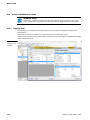
4.10.1 Topology-Scan......................................................................................................................................................................................4-32
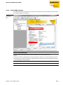
4.10.2 Special DTM parameters ...................................................................................................................................................................4-33
5
Modbus TCP
5.1
General ............................................................................................................................................................ 5-2
5.1.1
5.1.2
Implemented Modbus functions ..................................................................................................................................................... 5-2
Modbus registers ................................................................................................................................................................................... 5-2
– Register assignment ........................................................................................................................................................................ 5-3
– Register 100Ch: Module status .................................................................................................................................................... 5-6
– Register 1130h: Modbus connection mode............................................................................................................................ 5-6
– Register 1131h: Modbus Connection Timeout ...................................................................................................................... 5-6
– Register 0x113C and 0x113D: Restore Modbus-Connection-Parameters.................................................................... 5-7
– Register 0x113E and 0x113F: Save Modbus-Connection-Parameters........................................................................... 5-7
5.2
Data width of the TBEN-S2-4IOL in the Modbus-register area.................................................................... 5-8
5.3
Register mapping TBEN-S2-4IOL ................................................................................................................... 5-9
5.4
Error behavior (watchdog)........................................................................................................................... 5-10
5.4.1
5.4.2
Behavior of outputs ............................................................................................................................................................................5-10
Behavior of the BUS LED....................................................................................................................................................................5-10
5.5
Parameters and diagnostic messages of the I/O channels ....................................................................... 5-11
6
EtherNet/IP™
6.1
EDS-file ............................................................................................................................................................ 6-2
6.2
QC - QuickConnect .......................................................................................................................................... 6-3
6.3
Diagnostic messages via the process data ................................................................................................... 6-4
– Status word......................................................................................................................................................................................... 6-4
6.4
EtherNet/IP™-standard classes ...................................................................................................................... 6-5
6.4.1
6.4.2
6.4.3
6.4.4
6.4.5
Identity Object (0x01)........................................................................................................................................................................... 6-5
Assembly Object (0x04)....................................................................................................................................................................... 6-7
– Configuration Assembly (Instance 106) ................................................................................................................................... 6-8
– Process data instances.................................................................................................................................................................... 6-9
– Process data mapping TBEN-S2-4OIL........................................................................................................................................ 6-9
Connection Manager Object (0x06)..............................................................................................................................................6-10
TCP/IP Interface Object (0xF5) ........................................................................................................................................................6-10
Ethernet Link Object (0xF6)..............................................................................................................................................................6-14
6.5
VSC-Vendor Specific Classes ........................................................................................................................ 6-16
ii
D301369 - 0815 TBEN-S2-4IOL
6.5.1
6.5.2
6.5.3
6.5.4
6.5.5
Class Instance of the VSCs................................................................................................................................................................ 6-16
Gateway Class (VSC 100)................................................................................................................................................................... 6-17
– Class instance................................................................................................................................................................................... 6-17
– Object instance 1, boot instance .............................................................................................................................................. 6-17
– Object instance 2, gateway instance ...................................................................................................................................... 6-18
– Object instance 4, COS/CYCLIC instance ............................................................................................................................... 6-19
Miscellaneous Parameters Class (VSC 126) ................................................................................................................................ 6-20
DXP Class 135 (87h) ............................................................................................................................................................................ 6-21
IO-Link Port Class 137 (89h)............................................................................................................................................................. 6-23
7
PROFINET
7.1
GSDML-file .......................................................................................................................................................7-2
7.2
Configuration TBEN-S2-4IOL ..........................................................................................................................7-3
7.3
FSU - Fast Start-Up (prioritized startup) ........................................................................................................7-4
7.4
PROFINET-diagnostics - TBEN-S2-4IOL ..........................................................................................................7-5
7.5
Parameters .......................................................................................................................................................7-6
7.5.1
7.5.2
General module parameters ..............................................................................................................................................................7-6
Parameters for I/O channels ...............................................................................................................................................................7-6
7.6
Description of user data for acyclic services .................................................................................................7-7
7.6.1
7.6.2
7.6.3
Description of the acyclic device user data ..................................................................................................................................7-7
Description of the acyclic I/O-channel user data........................................................................................................................7-8
IM99 (IOL_M)............................................................................................................................................................................................7-9
8
The IO-Link function block IOL_CALL
8.1
General .............................................................................................................................................................8-2
8.2
IOL_CALL in accordance with IO-Link specification .....................................................................................8-2
8.2.1
8.2.2
8.2.3
8.2.4
Input variables.........................................................................................................................................................................................8-3
Output variables .....................................................................................................................................................................................8-4
STATUS - communication error status............................................................................................................................................8-5
IOL_STATUS..............................................................................................................................................................................................8-7
9
Integration of the IO-Link-Master in Step 7
9.1
Example project...............................................................................................................................................9-2
9.1.1
9.1.2
Used hardware ........................................................................................................................................................................................9-2
Used software ..........................................................................................................................................................................................9-2
9.2
Configuration in HW-Config ...........................................................................................................................9-3
9.2.1
9.2.2
Configuration of the IO-Link master................................................................................................................................................9-3
– Configuration of the virtual slots 2 - 5 (IO-Link-ports) in the example project........................................................... 9-5
Parameterization of the IO-Link ports.............................................................................................................................................9-6
9.3
Usage of the function block in Step 7 ............................................................................................................9-8
9.3.1
Example accesses with IOL_CALL.....................................................................................................................................................9-9
– Read access.......................................................................................................................................................................................... 9-9
– Write access...................................................................................................................................................................................... 9-11
10
Appendix
10.1
Start-up: IO-Link-Device with IO-Link V1.0 ................................................................................................ 10-2
D301369 - 0815 TBEN-S2-4IOL
iii
10.2
Start-up: IO-Link-Device with IO-Link V1.1................................................................................................. 10-3
10.3
Start-up problems - frequently failure causes............................................................................................ 10-4
11
Index
iv
D301369 - 0815 TBEN-S2-4IOL
1
About this manual
1.1
Documentation concept.................................................................................................................... 2
1.2
Explanation of symbols used ............................................................................................................ 3
1.2.1
1.2.2
Warnings .................................................................................................................................................................................................3
Further notes .........................................................................................................................................................................................3
1.3
General notes .................................................................................................................................... 4
1.3.1
1.3.2
Prescribed use .......................................................................................................................................................................................4
Notes concerning planning/installation of this product .......................................................................................................4
D301369 - 0815 TBEN-S2-4IOL
1-1
About this manual
1.1
Documentation concept
This manual contains all information about TBEN-S2-4IOL, the TURCK IO-Link Master module which is
part of TBEN-S product line. It provides 4 IO-Link channels and 4 configurable digital DXP-channels.
The following chapters contain:
A general device description and its process data image in the different Ethernet protocols,
A short description of the communication interface IO-Link,
A description of the IO-Link master functionality,
A general description of the function block (FB) IOL_Call and its in- and output variables,
A general description of the IO-Link-Master's integration in Step 7 including a description of the FB
IO-Link CALL in PROFINET,
Helpful information for the operation of IO-Link devices and a list of possible failure causes.
1-2
D301369 - 0815 TBEN-S2-4IOL
Explanation of symbols used
1.2
1.2.1
Explanation of symbols used
Warnings
Action-related warnings are placed next to potentially dangerous work steps and are marked by
graphic symbols. Each warning is initiated by a warning sign and a signal word that expresses the gravity of the danger. The warnings have absolutely to be observed:
DANGER!
DANGER indicates an immediately dangerous situation, with high risk, the death or severe
injury, if not avoided.
WARNING!
WARNING indicates a potentially dangerous situation with medium risk, the death or severe
injury, if not avoided.
CAUTION!
WARNING indicates a potentially dangerous situation with medium risk, the death or severe
injury, if not avoided.
ATTENTION!
CAUTION indicates a potentially dangerous situation with low risk, middle or low injury, if not
avoided.
1.2.2
Further notes
NOTE
In NOTES you find tips, recommendations and important information. The notes facilitate
work, provide more information on specific actions and help to avoid overtime by not following the correct procedure.
TECHNICAL BASICS
The technical basics offer technical information, the basics and background information. This
information lead to a better understanding of the device functions for example. The experienced user can skip this information.
CALL TO ACTION
This symbol identifies steps that the user has to perform.
RESULTS OF ACTION
This symbol identifies relevant results of steps
D301369 - 0815 TBEN-S2-4IOL
1-3
About this manual
1.3
General notes
Please read this section carefully. Safety aspects cannot be left to chance when dealing with electrical
equipment.
This manual includes all information necessary for the prescribed use of the modules of type TBEN-S24IOL. It has been specially conceived for personnel with the necessary qualifications.
1.3.1
Prescribed use
The devices described in this manual must be used only in applications prescribed in this manual or in
the respective technical descriptions, and only with certified components and devices from third party
manufacturers.
Appropriate transport, storage, deployment and mounting as well as careful operating and thorough
maintenance guarantee the trouble-free and safe operation of these devices.
1.3.2
Notes concerning planning/installation of this product
All respective safety measures and accident protection guidelines must be considered carefully and
without exception.
1-4
D301369 - 0815 TBEN-S2-4IOL
2
2.1
Further documentation
Product family TBEN-S ...................................................................................................................... 2
D301369 - 0815 TBEN-S2-4IOL
2-1
Further documentation
2.1
Product family TBEN-S
User manual D301347 "TBEN-S-product family, digital and analog standard modules"
The user manual for the TBEN-S product family describes comprehensive topics like for example:
– General technical data
– Mounting the TBEN-S-modules
– Connection options at module
– General information about Ethernet, the multiprotocol functionality and about the single protocols
– A description of the web server
– Information about the electrical installation
User manual D301348 „GETTING STARTED - First steps for commissioning TBEN-S-stations“
2-2
D301369 - 0815 TBEN-S2-4IOL
3
IO-Link
3.1
IO-Link - the fieldbus independent communication interface .......................................................... 2
3.1.1
3.1.2
3.1.3
3.1.4
General technical information.........................................................................................................................................................2
Data transmission ................................................................................................................................................................................3
Transmission media.............................................................................................................................................................................4
Fieldbus/Ethernet integration.........................................................................................................................................................4
D301369 - 0815 TBEN-S2-4IOL
3-1
IO-Link
3.1
IO-Link - the fieldbus independent communication interface
TECHNICAL BASICS
IO-Link is a fieldbus-independent communication interface for sensors and actuators.
It is based on the IO-Link specification "IO-Link Interface and System Specification"
version 1.1.2, November 2012, and on the IEC 61131-9 (2013-09), ed. 1.0, „Programmable
controllers - part 9: Single-drop digital communication interface for small sensors and
actuators (SDCI)“.
IO-Link is a point-to-point connection between an IO-Link device (e.g. sensor, I/O hub, valve
terminal) and the IO-Link master. Up to now, the binary connection was only designed for
transferring switching information, but IO-Link now allows 2 bytes to be transferred normally
in a 2.3 ms cycle via a combined switching status and data channel.
Other information can be exchanged in addition to the process values, such as parameters or
diagnostic messages.
This enables communication with sensors and actuators down to the "last meter" to be established for universal communication.
3.1.1
General technical information
TECHNICAL BASICS
– Standard I/O-connection technologies in point-to-point connection, unshielded, 20 m
wire length
– Cyclic process data transfer in typ. 2.3 ms
– Parallel service data exchange without any impact on the process data
– Communication via 24 V-pulse modulation, standard UART protocol
– Communication between master and device in 3 different transmission speeds
– 4.800 Baud (COM 1)
– 38.400 Baud (COM 2)
– 230.400 Baud (COM 3)
3-2
D301369 - 0815 TBEN-S2-4IOL
IO-Link - the fieldbus independent communication interface
3.1.2
Data transmission
TECHNICAL BASICS
Basically 4 different types of data exist, which are transmitted either cyclically or acyclically.
– Process data cyclic data exchange
– Value status cyclic data exchange
– Device data acyclic data exchange
– Events acyclic data exchange
Process data:
The devices' process data are transmitted cyclically, whereas the process data size is defined
through the device. The device process data can contain from 0 to 32 Byte (for both in- and
output).
Value status:
The value status displays if process data are valid or not. It is transmitted cyclically with the
process data.
Device data:
Device data are parameters, identification data and diagnostic information. The transmission is done acyclically and only on demand of the IO-Link master.
Events:
Events are error messages or warnings/maintenance data. Error messages are transmitted
from the device to the PLC or similar via the IO-Link master. The IO-Link master itself can
also transmit events and status information. Those events can be for example an open circuit, communication loss or an overload.
D301369 - 0815 TBEN-S2-4IOL
3-3
IO-Link
3.1.3
Transmission media
TECHNICAL BASICS
IO-Link does not require any special wiring. The sensors and actuators can continue to be connected using the proven, attractively priced and unshielded industrial cables.
The operating modes available for selection are the standard switch mode and the communication mode.
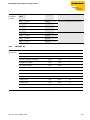
3.1.4
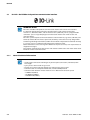
Fieldbus/Ethernet integration
TECHNICAL BASICS
– Usage of the standard-transport mechanisms of established fieldbusses/sensor/actuator
busses
– (DPV0, DPV1, Ethernet …)
– Simple integration in engineering systems by means of configuration files (GSD, GSDML,
…)
– Comfortable usage of even complex product features by means of tool based engineering
(FDT/DTM, …)
Figure 3-1:
IO-Link overview
3-4
D301369 - 0815 TBEN-S2-4IOL
4
TBEN-S2-4IOL
4.1
General.............................................................................................................................................. 2
4.2
Block diagram ................................................................................................................................... 3
4.3
Technical data ................................................................................................................................... 4
4.4
Wiring diagram ................................................................................................................................. 5
4.4.1
4.4.2
Ethernet/voltage supply....................................................................................................................................................................5
IO-Link ports...........................................................................................................................................................................................5
4.5
Process data ...................................................................................................................................... 6
4.5.1
4.5.2
Process input data ...............................................................................................................................................................................6
Process output data ............................................................................................................................................................................8
4.6
Parameters........................................................................................................................................ 9
4.6.1
Adaptation of the process data mapping ................................................................................................................................ 14
4.7
Device status ................................................................................................................................... 15
4.7.1
4.7.2
LED behavior....................................................................................................................................................................................... 15
Diagnostic data .................................................................................................................................................................................. 17
– Diagnostic telegram.................................................................................................................................................................... 17
Status- and control word................................................................................................................................................................ 21
– Status word ..................................................................................................................................................................................... 21
– Control word................................................................................................................................................................................... 21
4.7.3
4.8
IO-Link data storage ....................................................................................................................... 22
4.8.1
4.8.2
4.8.3
4.8.4
4.8.5
General.................................................................................................................................................................................................. 22
Parameter "data storage mode" = activated........................................................................................................................... 23
Parameter "data storage mode" = read in................................................................................................................................ 25
Parameter "data storage mode" = overwrite .......................................................................................................................... 25
Parameter "data storage mode" = deactivated, clear ......................................................................................................... 25
4.9
IO-Link - functions for acyclic communication ................................................................................ 26
4.9.1
Port functions for port 0 (IO-Link master) ................................................................................................................................ 26
– Subindex 64: Master Port Validation Configuration......................................................................................................... 26
– Subindex 65: IO-Link Events...................................................................................................................................................... 26
– Subindex 66: Set Default Parameterization......................................................................................................................... 28
– Subindex 67: Teach Mode ......................................................................................................................................................... 28
– Subindex 68: Master Port Scan Configuration.................................................................................................................... 29
– Subindex 69: Extended Port Diagnostics ............................................................................................................................. 30
– Device Status .................................................................................................................................................................................. 31
4.10
IO-Link and TURCK device DTMs..................................................................................................... 32
4.10.1
4.10.2
Topology-Scan ................................................................................................................................................................................... 32
Special DTM parameters................................................................................................................................................................. 33
D301369 - 0815 TBEN-S2-4IOL
4-1
TBEN-S2-4IOL
4.1
General
The TBEN-S2-4IOL is the four-channel IO-Link-master module of the product family TBEN-S.
Like all modules of the TBEN-S-product family, the TBEN-S2-4IOL is a device with multiprotocol functionality. An integrated Ethernet-switch allows the building up of a line topology.
In addition to the four IO-Link-channels, the TBEN-S2-4IOL provides four universal digital DXP-channels
(PNP).
The four IO-Link channels can be parameterized independently and can optionally be operated in IOLink mode (IOL) or in standard I/O mode (DI mode).
The four universal digital channels are designed as DXP-channels and can therefore be parameterized
as in- or output.
Properties:
4-channel IO-Link master according to IO-Link specification V1.1
4 universal digital channels, PNP, channel diagnostics, 0,5 A
4-2
D301369 - 0815 TBEN-S2-4IOL
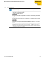
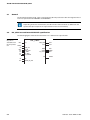
Block diagram
4.2
Block diagram
Figure 4-1:
Block diagram,
TBEN-S2-4IOL
4IOL
X1
+
2
V1
–
3
+
1
In/Output
X2
V2
–
4
+
2
V1
–
3
+
1
V2
1 V2 +
–
4
V2 +
Supply
IN Diag
V1 +
2 IN/OUT
I/O
3 V2 –
4 C/Q
OUT Diag
5 n.c.
V2 +
IO-Link Data
IO-Link
μC
IO-Link Diag
μC
V1 Diag
V2 Diag
IN Diag
OUT Diag
IO-Link Data
IO-Link Diag
BUS
μC
ERR
PWR
Ethernet
Ethernet
4
3
2
1
P1
D301369 - 0815 TBEN-S2-4IOL
ETH1
ETH2
4
3
2
1
P2
4-3
TBEN-S2-4IOL
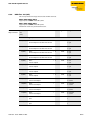
4.3
Technical data
Table 4-1:
Technical data
Type designation
TBEN-S2-4IOL
Power supply
24 V DC from operating voltage
Permissible range
20,4 … 28,8 V DC (acc. to IO-Link standard)
Operating current
< 120 mA
Sensor/actuator supply VAUX2
supply connector C1 - C4 from V2
not short-circuit proof, 4 A per group C1 - C4
Potential isolation
500 V (V2 to Ethernet and V1)
IO-Link
Number of ports
4
IO-Link specification
V1.0, V1.1 according to IEC 61 61131-9
IO-Link port type
Class A
Frame type
supports all specified frame types
Process data for IO-Link devices
– Input data
max. 32 Byte per channel
– Output data
max. 32 Byte per channel
Transmission rate
4,8 kbps (COM 1)
38,4 kbps (COM 2)
230,4 kbps (COM 3)
Transmission cable
length: max. 20 m
standard cables,
3- or 4-wire (depending on the application),
unshielded
NOTE
General technical data concerning the products of the TBEN-Sx series can be found in
D301347 - "TBEN-S-product family, digital and analog standard modules"
4-4
D301369 - 0815 TBEN-S2-4IOL
Wiring diagram
4.4
4.4.1
Wiring diagram
Ethernet/voltage supply
NOTE
Please find further information about the connectors for Ethernet and the voltage supply in
the user manual D301347: "TBEN-S product family, digital and analog standard modules",
chapter 5, "Connectors at the device".
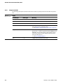
4.4.2
IO-Link ports
Figure 4-2:
Pin assignment of
M12 x 1-connectors, 5-pole
v
1 = Vaux2
2 = DXP
3 = V2 –
4 = C/Qx
5 = n.c.
2
3
1
5
4
Pin 1: VAUX2 not short-circuit proof
Pin 2: digital in- or output
Pin 4: IO-Link or digital input
C1...C4
ATTENTION!
Wrong supply of IO-Link devices (Class A)
Damage to the electronics
The IO-Link devices (Class A) must only be supplied with the voltage provided at the supply
terminals
D301369 - 0815 TBEN-S2-4IOL
4-5
TBEN-S2-4IOL
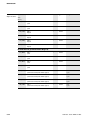
4.5
Process data
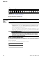
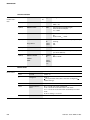
4.5.1
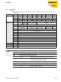
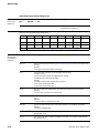
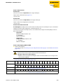
Process input data
Byte
Bit 7
Bit 6
Bit 5
Bit 4
Module
Bit 3
Bit 2
Bit 1
Bit 0
Status
0
DXP8
DI7 (SIO)
DXP6
DI5 (SIO)
1
DXP4
DI3 (SIO)
DXP2
DI1 (SIO)
-
DVS3
-
DVS1
-
ERR
DXP 2
-
-
2
-
DVS7
-
DVS5
3
-
IO-Link
ports
IO-Link process input data
Port 1
4 - 35
Port 2
36 - 67
Port 3
68 - 99
Port 4
100 - 131
structure depends on the channel parameterization
(0 - 32 byte per channel)
Diagnostics
(see Diagnostic data (page 4-17))
DXPchannels
ERR
DXP 8
132
ERR
DXP 6
-
133
reserved
IO-Link
ports
Port 1
(see Diagnostic data (page 4-17))
134
EVT1
EVT2
PDINV
HWER
DSER
CFGER
PPE
-
135
GENER
OVL
VHIGH
VLOW
ULVE
LLVU
OTMP
PRMER
Port 2
136 - 137
Port 3
138 - 139
Port 4
140 - 141
assignment similar to port 1
IO-Link
ports
IO-Link Events
(description, see Subindex 65: IO-Link Events (page 4-26))
142
Qualifier (1st Event)
143
Port (1st Event)
144
Event Code high byte (1st Event)
145
Event Code low byte (1st Event)
...
...
202
Qualifier (16th Event)
203
Port 16th Event)
204
Event Code high byte (16th Event)
205
Event Code low byte (16th Event)
Module
Module status (status word)
(see Status- and control word (page 4-21))
206 - 207
V2
-
4-6
ERR
DXP 4
-
FCE
-
-
Diag
-
-
V1
-
D301369 - 0815 TBEN-S2-4IOL
Process data
Table 4-2:
Name
Process input data
DIx
DXPx
DVSx
ERR
DXP x
Value
Meaning
Digital input
0
No signal at DI (pin 4, SIO)
1
Input signal at DI (pin 4, SIO)
DXP input
0
No input signal at DXP-channel (pin 2)
1
Input signal at DXP-channel (pin 2)
Input value valid (Data Valid Signal)
0
The IO-Link data are valid.
Possible causes:
– Sensor supply is below the admissible range,
– IO-Link port is parameterized as simple digital input,
– No device connected to the masters,
– No input data received from the connected device (only valid for devices with
an input data length > 0),
– No reaction from the connected device to the sending of output data (only
valid for devices with an output data length > 0),
– The connected device sends an error "process input data invalid.
1
The IO-Link data are valid.
Overcurrent output
0
No overcurrent
1
Overcurrent at the output (if the DXP channel is used as output)
IO-Link process input data
Process input data of the connected device
The order of the IO-Link process input data can be changed via the parameter "Process input data
mapping" (page 4-9).
D301369 - 0815 TBEN-S2-4IOL
4-7
TBEN-S2-4IOL
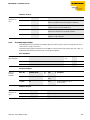
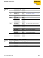
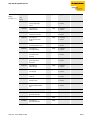
4.5.2
Process output data
Byte
Module
0
Bit 7
Bit 6
DXP8
Bit 5
-
Bit 4
DXP6
1
-
Bit 3
Bit 2
DXP4
Bit 1
-
DXP2
Bit 0
-
reserved
IO-Link process output data
Port 1
2 - 33
Port 2
34 - 65
Port 3
66 - 97
Port 4
98 - 129
Table 4-3:
Process output
data
Name
Value
DXPx
DXP output
Structure depends on the channel parameterization
(0 - 32 byte per channel)
Meaning
0
Output inactive
1
Output active, max. output current 0.5 A
IO-Link process output data
Process output data of the connected device
The order of the IO-Link process output data can be changed via the parameter "Process output data
mapping" (page 4-9).
4-8
D301369 - 0815 TBEN-S2-4IOL
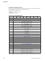
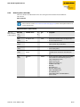
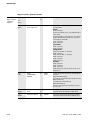
Parameters
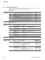
4.6
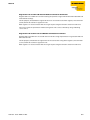
Parameters
The module provides 4 byte of module parameters and 16 byte of IO-Link port-parameters for each
IO-Link port.
Byte
Module
Bit 7
0
Bit 6
SRO8
-
Bit 5
SRO6
Bit 4
Bit 3
-
1
2
EN DO8
-
GSD
Quick
Start-Up
5
SRO4
-
SRO2
-
EN DO6
-
EN DO4
-
EN DO2
-
Data storage mode
Mode
Cycle time
Process output data
mapping
7 - 11
Process input data
mapping
Deactivate
diagnostics
12
Vendor ID (LSB)
13
Vendor ID (MSB)
14
Device ID (LSB)
15
Device ID
16
Device ID
17
Device ID (MSB)
18
reserved
19
reserved
20 - 35
Assignment similar to port 1 (byte 4 - 19 )
Port 3
36 - 51
Assignment similar to port 1 (byte 4 - 19 )
Port 4
52 - 67
Assignment similar to port 1 (byte 4 - 19 )
Name
Process input Revision
data invalid
reserved
Port 2
Table 4-4:
Parameter
Bit 0
-
4
6
Bit 1
-
3
Port 1
Bit 2
Meaning
Value
A default setting
SRO
Manual output reset after overcurrent
0
0 = no A
The output switches on automatically after an overload.
1
1 = yes
The output is manually switched-off after an overload until a
new set-command is given (rise and fall).
EN DO
Activate output
0
0 = no A
The output at pin 2 is deactivated.
1
1 = yes
The output at pin 2 is activated.
D301369 - 0815 TBEN-S2-4IOL
4-9
TBEN-S2-4IOL
Table 4-4:
Parameter
Name
Meaning
Value
A default setting
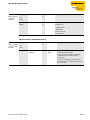
4-10
Mode
0000
IO-Link without
validation A
Pin 4 is operated in IO-Link mode.
The master does not check if the connected device matches the
configured one.
0001
IO-Link with family
compatible device
Pin 4 is operated in IO-Link mode.
The master checks if the Vendor ID and the MSB of the Device
ID (this byte defines the product family) of the connected
device match those of the configured one.
If the master detects a mismatch, the IO-Link communication is
established, but there is no process data exchange. The device
remains in the safe state (Pre-Operate). Parameters and diagnostic information can be read and respectively written.
0010
IO-Link with compati- Pin 4 is operated in IO-Link mode.
ble device
The master checks if the Vendor ID and the Device ID of the connected device match those of the configured one.
If the Vendor ID matches, but the Device ID not, then the master
tries to write the Device ID to the device.
If the writing is successful, then the device is a compatible one,
process data exchange is possible.
If writing the Device ID is not successful, then process data
exchange is not possible. The device remains in the safe state
(Pre-Operate). Parameters and diagnostic information can be
read and respectively written.
0011
IO-Link with
identical device
Pin 4 is operated in IO-Link mode.
The master checks if the device type (Vendor ID and Device ID)
and the serial number of the connected device match the data
of the configured one.
If the master detects a mismatch, the IO-Link communication is
established, but there is no process data exchange. The device
remains in the safe state (Pre-Operate). Parameters and diagnostic information can be read and respectively written.
0100
DI (with parameter
access)
Pin 4 is generally operated as simple digital input.
However, an acyclic parameter access from the PLC or the DTM
is possible.
The IO-Link master starts the port in IO-link mode, parameterizes the device and sets the port back into DI-mode. The port
remains in DI mode until a new IO-Link request is sent from the
higher-level control.
Data storage is not supported!
Connected devices have to support the SIO-mode (DI-mode).
D301369 - 0815 TBEN-S2-4IOL
Parameters
Table 4-4:
Parameter
Name
Meaning
Value
A default setting
0101
DI:
Pin 4 is operated as simple digital input.
Data storage is not supported!
NOTE
Parameter Mode", "DI (with parameter access)“:
In case of a parameter access, the IO-Link communication at the port is started.
Switching signals are interrupted!
Data storage mode
Synchronization of parameter data of IO-Link devices (storing the parameter of the connected device
in the master).
If the synchronization is not possible, a diagnostic message is displayed (DSERR, see Diagnostic data
(page 4-17)). In this case select option "11 = deactivated, clear" in order to clear the data buffer of the
device.
00
activated
Synchronization of parameter data activated. The most actual
data (master or device) serve as the reference data.
01
overwrite
Synchronization of parameter data activated, the data in the
master serve as reference data.
10
read in
Synchronization of parameter data activated. The data in the
connected IO-Link device serve as reference data.
11
deactivated, clear A
Synchronization of parameter data deactivated. The data set in
the master is deleted.
NOTE
IO-Link devices in accordance with IO-Link specification V1.0 do not support data storage.
In this case the data storage has to be deactivated (data storage mode: 11 = deactivated,
clear).
Activate Quick Start-Up
For fast applications (e.g. tool changing applications) the start-up time of IO-Link devices can be shortened. The start-up time defined in the IO-Link specification (TSD = Device Detection Time) is reduced.
00
no A
The start-up time is within the specified range (0.5 s). All IO-Link
devices in accordance with the specification can be operated.
01
yes
The start-up time is reduced to approx. 100 ms. It is not supported by every IO-Link device.
It can thus be necessary to check if the used IO-Link device
starts in this mode.
D301369 - 0815 TBEN-S2-4IOL
4-11
TBEN-S2-4IOL
Table 4-4:
Parameter
Name
Meaning
Value
A default setting
Device parameterization via GSD
0
inactive A
The port is parameterized as generic port or not parameterized.
1
active
The port is parameterized in PROFINET with a specific device
type from the GSDML-file.
00
automatic A
The Master reads the minimum cycle time from the connected
device.
00000001 11001111
(0×01 0×BF)
0.8 to 132.8 ms
Settable in steps of 0.8 or 1.6 ms.
(see Table 4-5: Parameter values "cycle time" [ms] (page 4-13))
00
automatic A
The Master defines the IO-Link-revision automatically.
01
V1.0
IO-Link-Revision V 1.0 is used.
Cycle time
Revision
Process input data invalid
00
diagnostics
generated A
If the process data are invalid, a respective diagnostic message
is generated.
01
no diagnostics
generated
Invalid process data do not cause a diagnostic message.
Deactivate diagnostics
Influences the sending of IO-Link-Events from the master to the fieldbus. Depending on the parameterization, the master transmits Events based on their priority to the fieldbus or not.
00
no
The master transmits all IO-Link Events to the fieldbus.
01
notifications
The master transmits all IO-Link Events to the fieldbus except
for IO-Link notifications.
10
Notifications and
warnings A
The master transmits all IO-Link Events to the fieldbus except
for IO-Link notifications and warnings.
11
yes
The master doesn't transmit any IO-Link Event to the fieldbus.
Process input data mapping
Optimization of the process data mapping for the used fieldbus:
The I/O-Link-data can be swapped depending on the used fieldbus in order to achieve an optimized
data mapping on the fieldbus side.
4-12
00
direct A
The process data are not swapped.
(0×0123 4567 89AB CDEF)
01
swap 16 bit
The bytes are swapped per word.
(0×2301 6745 AB89 EFCD)
D301369 - 0815 TBEN-S2-4IOL
Parameters
Table 4-4:
Parameter
Name
Meaning
Value
A default setting
10
swap 32 bit
The bytes are swapped per double word.
(0× 6745 2301 EFCD AB89)
11
swap all
All bytes are swapped.
(0×EFCD AB89 6745 2301)
Process output data mapping
see: Process input data mapping
Vendor ID
Enter the IDs for the port configuration check.
0x0000 0xFFFF
Device ID
0x0000 0xFFFF
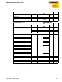
Values for the parameter "cycle time" [ms]:
Table 4-5:
Parameter values "cycle time"
[ms]
Time
Value
Time Value
Time Value
Time Value
Time
Value
Time
Value
auto A 0×00
15.2
0×56
30.4
0×7C
59.2
0×91
89.6
0×A4
120
0×B7
0.8
0×08
16
0×58
31.2
0×7E
60.8
0×92
91.2
0×A5
121.6
0×B8
1.6
0×10
16.8
0×5A
32
0×80
62.4
0×93
92.8
0×A6
132.2
0×B9
2.4
0×18
17.6
0×5C
33.6
0×81
64
0×94
94.4
0×A7
124.8
0×BA
3.2
0×20
18.4
0×5E
35.2
0×82
65.6
0×95
96
0×A8
126.4
0×BB
4
0×28
19.2
0×60
36.8
0×83
67.2
0×96
97.6
0×A9
128
0×BC
4.8
0×30
20
0×62
38.4
0×84
68.8
0×97
99.2
0×AA
129.6
0×BD
5.6
0×38
20.8
0×64
40
0×85
70.4
0×98
100.8
0×AB
131.2
0×BE
6.4
0×40
21.6
0×66
41.6
0×86
72
0×99
102.4
0×AC
132.8
0×BF
7.2
0×42
22.4
0×68
43.2
0×87
73.6
0×9A
104
0×AD
-
-
8
0×44
23.2
0×6A
44.8
0×88
75.2
0×9B
105.6
0×AE
-
-
8.8
0×46
24.0
0×6C
46.4
0×89
76.8
0×9C
107.2
0×AF
-
-
9.6
0×48
24.8
0×6E
48
0×8A
78.4
0×9D
108.8
0×B0
-
-
10.4
0×4A
25.6
0×70
49.6
0×8B
80
0×9E
110.4
0×B1
-
-
11.2
0×4C
26.4
0×72
51.2
0×8C
81.6
0×9F
112
0×B2
-
-
12.0
0×4E
27.2
0×74
52.8
0×8D
83.2
0×A0
113.6
0×B3
-
-
12.8
0×50
28
0×76
54.4
0×8E
84.8
0×A1
115.2
0×B4
-
-
13.6
0×52
28.8
0×78
56
0×8F
86.4
0×A2
116.8
0×B5
-
-
14.4
0×54
29.6
0×7A
57.6
0×90
88
0×A3
118.4
0×B6
-
-
A automatic: The lowest cycle time supported by the device is taken from the table.
D301369 - 0815 TBEN-S2-4IOL
4-13
TBEN-S2-4IOL
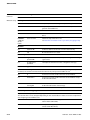
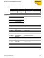
4.6.1
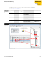
Adaptation of the process data mapping
The mapping of process data can be adapted application-specifically via the IO-Link-master's parameterization.
Depending on the used fieldbus, it can be necessary to swap process data word-wise, double wordwise or completely in order to align them to the data structure in the PLC.
The process data mapping is determined channel by channel through the parameters "process input
data mapping" and "process output data mapping" (see Parameters (page 4-9)).
Example mapping for field buses with Little Endian-format:
Maaping from master
fieldbus PLC
Devices at channel
1... 4
Byte (A)
Byte 0
Status
Byte 1
Control
Parametrierung Process output data mapping
of the channel
(see
page 4-9)
IO-Link device
Byte (A)
PORT1
Byte 2
Temperature
Byte 3
Low byte
High byte
2 byte process
data
(swap 16 bit)
Temperature
2 byte process
data
(swap 16 bit)
Position
2 byte process
data (direct)
Digital signal
1... 7
Digital signal
8 ...15
4 byte process
data
(swap all)
Counter/
position value
MSByte
High byte
Low byte
PORT2
Byte 4
Position
Byte 5
Low byte
High byte
High byte
Low byte
PORT3
Byte 6
Digital signal
1... 7
Byte 7
Digital signal
8 ...15
PORT4
Byte 8
Diagnosis
Byte 9
Counter/
position value
Byte 10
Byte 11
Low byte
High byte
MSByte
High byte
Low byte
Diagnosis
A Low byte, the lowest byte Low-Byte
High byte High-Byte
MSByte: Most Significant Byte
4-14
D301369 - 0815 TBEN-S2-4IOL
Device status
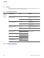
4.7
4.7.1
Device status
LED behavior
The following table describes the protocol-independent behavior of the device LEDs.
The description of protocol-specific LED-behavior can be found in the respective sub-chapters.
Table 4-6:
LED behavior
LED
Color Status
Meaning
Remedy
PWR
green off
V1 missing or < 18 V DC
Check V1
on
V1 and V2 OK
-
on
V2 missing or < 18 V DC
Check V2
Red
ETHx
ERR
BUS
green on
Link established,100 Mbps
flashing
Ethernet Traffic, 100 Mbps
yellow
on
Link established,100 Mbps
flashing
Ethernet Traffic, 10 Mbps
-
off
no Ethernet link
green on
No diagnostic message available
red
Diagnostic message pending
on
green on
Red
Active connection to a master
-
blinking
Device is ready for operation
-
on
IP address conflict or restore mode
or timeout
control IP addresses in the network
waiting for the device to be ready
for operation
blinking
Blink-/wink-command active
see also description of LED "C8"
red/
on
green
D301369 - 0815 TBEN-S2-4IOL
Check the Ethernet connection.
Autonegotiation and/or waiting
for DHCP-/BootP-address assignment.
4-15
TBEN-S2-4IOL
Table 4-6:
LED behavior
LED
Color Status
Meaning
IOLx
Channel in IO-Link-mode
No IO-Link communication, diagnostics deactivated
– connect an IO-Link device
– Parameterize the channel as DI if
necessary.
flashing
IO-Link communication active,
valid process data
-
Red
on
No IO-Link communication and/or Possible causes:
module error,
– Sensor supply is below the
invalid process data
admissible range,
– IO-Link port is parameterized as
simple digital input,
– No device connected to the masters,
Red
flashing
IO-Link communication active and – No input data received from the
connected device (only valid for
module error,
invalid process data
devices with an input data length
> 0),
– No reaction from the connected
device to the sending of output
data (only valid for devices with
an output data length > 0),
– connected device sends an error:
"process data invalid".
see also:
Start-up problems - frequently
failure causes (page 10-4)
Green off
Channel in DI-mode
DXPx
Green off
-
Green on
Input signal active
Green off
-
Green on
In-/ output signal active
Red
on
Short circuit at output of the
respective channel
flashing
Support for localizing a module if
the blink-/wink-command is activated
DXP 8 white
4-16
Remedy
–
–
-
D301369 - 0815 TBEN-S2-4IOL
Device status
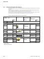
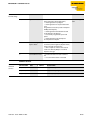
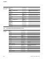
4.7.2
Diagnostic data
Diagnostic messages are distinguished between DXP-diagnostics, IO-Link-master diagnostics and IOLink-device diagnostics.
The „PDinvalid" diagnostic (process data invalid) can be sent from both devices, IO-Link master or IO-Link
device.
DXP-diagnostics
Diagnostic messages of the digital channels of the module (DXP 2, 4, 6, 8).
Master diagnostics
The IO-Link-master reports problems within the IO-Link communication.
Device diagnostics
The device diagnostics map the IO-Link Event codes (according to the IO-Link specification) sent
from the IO-Link devices to the diagnostic telegram of the master.
to the diagnostic telegram of the master.
Event codes can be read from the connected devices by using appropriate device tools (e.g. IODDInterpreter).
Further information about the IO-Link Event codes and their meaning can be found in the
IO-Link specification or in the documentation of the connected IO-Link devices.
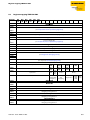
Diagnostic telegram
Channel
Byte
Bit 7
Bit 6
Bit 5
Bit 4
Bit 2
Bit 0
0
ERR
DXP 8
-
ERR
DXP 6
-
ERR
DXP 4
-
ERR
DXP 2
-
1
-
-
-
-
-
-
-
-
IO-Link
Device diagnostics
Master diagnostics
0
EVT1
EVT2
PDINV
HWER
DSER
CFGER
PPE
-
1
GENER
OLV
VHIGH
VLOW
ULVE
LLVU
OTMP
PRMER
IO-Link port 2
2+3
assignment similar to port 1
IO-Link port 3
4+5
assignment similar to port 1
IO-Link port 4
6+7
assignment similar to port 1
Table 4-7:
Diagnostic data
Bit 1
DXP-diagnostics
DXP
IO-Link port 1
Bit 3
Bit
Meaning
Remedy
DXP-diagnostics
ERR DXP x
D301369 - 0815 TBEN-S2-4IOL
Overcurrent output
0
No overcurrent
1
Overcurrent at the output (if the DXP channel is used as output)
4-17
TBEN-S2-4IOL
Table 4-7:
Diagnostic data
Bit
Meaning
Remedy
Master diagnostics
PPE
port parameterization error
The port parameters are inconsistent.
The device parameterization via GSD is active, but not working.
Possible causes:
The IO-Link-master did not receive GSDML-parameters for a connected device. The
connected device was not parameterized by a PROFINET PLC via GSDML.
The port is in operation mode "IO-Link without validation" or "DI". These modes do not
allow parameterization via GSD.
The data storage mode is active, which means, the parameter is not set to "deactivated,
clear". A device parameterization via GSDML is not possible with activated data storage.
Vendor or Device ID are "0". The connected device can not be identified and is thus not
parameterizable.
CFGER
Wrong or missing device
The connected device does not match the
channel configuration or there is no
device connected to the channel.
This diagnostic message depends on the
parameterization of the channel (see
parameters, page 4-10).
DSER
Change the parameterization of the IOLink port at the master.
Correct the vendor-ID, device-ID, etc.
The parameterization can be done by
teaching the master via IOL_CALL using
the port function Subindex 67: Teach
Mode or via a manual port parameterization.
data storage error
Possible causes:
– Data storage mismatch
IO-Link device in accordance with IO-Link
V1.0 connected.
Deactivate the data storage.
To do so, set parameter
"Data storage mode" to "deactivated,
clear", see page 4-11.
The data storage buffer contains data of
another device.
Clear the data storage buffer of the master.
To do so, set the parameter "Data storage
mode" to "deactivated, clear", see page
4-11, and re-activate the data storage if
necessary.
4-18
D301369 - 0815 TBEN-S2-4IOL
Device status
Table 4-7:
Diagnostic data
Bit
Meaning
Remedy
– Overflow of the data storage buffer
Clear the data storage buffer of the master.
To do so, set the parameter "Data storage
mode" to "deactivated, clear", see page
4-11, and re-activate the data storage if
necessary.
– Parameter access for data storage not
possible
The connected device may be locked for
parameter changes or for data storage.
Check the status of the IO-Link index
"Device Access Locks" (index 0×C) of the
connected device and unlock the device.
Master/device diagnostics
PDINV
process input data invalid
The IO-Link master or the IO-Link device
report invalid process input data.
The connected device is not in status
"operate", which means, it is not ready for
operation.
Possible sources:
The connected device does not match the
configured one, additional diagnostic
message Wrong or missing device.
Certain IO-Link devices send a "process
input data invalid"-diagnosis if the process
value cannot be measured.
Deactivate the sending of the "process
input data invalid"-diagnosis for the
respective port. To do so, change the
parameter "Process input data invalid" to
"no diagnostics generated", see page 4-12.
Device diagnostics
For the exact specification of the device diagnostics, please read the device documentation of the
device manufacturer.
HWER
hardware error
General hardware error or device malfunction.
EVT2
out-of-specification events
An Out-of-Specification Event in accordance with the IO-Link specification occurred.
EVT1
maintenance events
A Maintenance Event in accordance with the IO-Link specification occurred, maintenance necessary.
PRMER
parameterization error
The connected device reports a parameterization error (loss of parameters, no parameter initialization, etc.)..
D301369 - 0815 TBEN-S2-4IOL
4-19
TBEN-S2-4IOL
Table 4-7:
Diagnostic data
Bit
Meaning
OTMP
overtemperature
Remedy
Temperature diagnostic message at the connected device.
LLVU
lower limit value underrun
The process value lies under the parameterized measurement range or the chosen
measurement range has been chosen too high.
ULVE
upper limit value exceeded
The process value exceeds the parameterized measurement range or the chosen measurement range has been chosen too low.
VLOW
undervoltage
One of the voltages at the connected device is below the defined range.
VHIGH
overvoltage
One of the voltages at the connected device is below the defined range.
OLV
Overload
The connected device detected an overload.
GENER
Common error
The device sends an error (device status 4, in accordance with IO-Link specification),
which is not clearly specified.
Read out the device event codes in order to be able to specify the error more precisely.
4-20
D301369 - 0815 TBEN-S2-4IOL
Device status
4.7.3
Status- and control word
Status word
EtherNet/IP™ PROFINET
Modbus
Table 4-8:
Byte 0
Byte 1
Byte 1
Byte 0
Bit 7
Bit 6
Bit 5
Bit 4
V2
-
Bit 3
Bit 2
Bit 1
FCE
-
-
Bit 0
DIAG
-
COM
V1
-
Name
Value
Description
COM
0
-
1
Internal error, the device-internal communication is disturbed.
0
-
1
Diagnostics available at the device.
0
-
1
The Force Mode is activated, which means, the actual output values may
no match the ones defined and sent by the field bus.
0
-
1
System power supply too low (< 18 V DC).
0
-
1
V2 too low (< 18 V DC).
Status word bits
DiagWarn
FCE
V1
V2
Control word
No function
The status word is mapped into the module's process data.
EtherNet/IP™
In EtherNet/IP™, the mapping can be disabled (seeGateway Class (VSC 100), GW Status Word (page
6-18) and GW Control Word (page 6-18)).
ATTENTION!
Activate/deactivate the Status and Control Word in EtherNet/IP™
Changes in the process data mapping
Observe that activating/deactivating the Status and Control Word causes changes in the
process data mapping.
Modbus TCP
see Register 100Ch: Module status (page 5-6)
PROFINET
see PROFINET-diagnostics - TBEN-S2-4IOL (page 7-5)
D301369 - 0815 TBEN-S2-4IOL
4-21
TBEN-S2-4IOL
4.8
4.8.1
IO-Link data storage
General
Data storage enables a user to change an IO-Link device when maintenance is required without any
configuration or parameterization.
The IO-Link master, as well as the IO-link device, store the device parameters. The data storage mechanism serves for synchronizing these different data storage buffers.
In case of a device change, the master writes the stored device parameters to the new device. The
application can be re-started without any further intervention using a configuration tool or similar.
In the IO-Link master, the data storage mode can be set using the parameter "data storage mode" (see
Parameters (page 4-9)).
data storage mode
00 = activated (page 4-23)
01 = overwrite (see page 4-25)
10 = read in (see page 4-25)
11 = deactivated, clear (see page 4-25)
Figure 4-3:
General principle
of the data storage mechanism
IO-Link-Master
(IOLM)
IO-Link-Device
(IOLD)
DS_UPLOAD_FLAG
Para. IOLD = parameter data of the IO-Link device
A change of parameters in the device is indicated by the status of the DS_UPLOAD_FLAG bit:
DS_UPLOAD_FLAG:
0 = no changes in the device's parameter set
1 = changes in the device's parameter set (e. g. via DTM, at the device, etc.)
4-22
D301369 - 0815 TBEN-S2-4IOL
IO-Link data storage
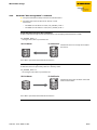
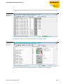
4.8.2
Parameter "data storage mode" = activated
The synchronization of the parameter sets is bidirectional.
The most actual data set (master or device) is valid:
This means:
– The data set in the device is actual, if DS_UPLOAD_FLAG = 1
– The data set in the master is actual, if DS_UPLOAD_FLAG = 0
Parameterizing a device in the installation:
A device, which is already used in the installation, is for example parameterized via a DTM.
DS_UPLOAD_FLAG = 1
changes in the device's parameter see
IO-Link-Master
IO-Link-Device
1
The IO-Link device is already connected to
the master.
Para. IOLD = parameter data of the IO-Link device
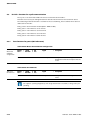
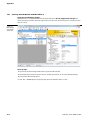
Maintenance - exchange device in delivery status:
A defective device is replaced by a device in delivery status.
DS_UPLOAD_FLAG = 0
no changes in the device's parameter set
IO-Link-Master
IO-Link-Device
0
The IO-Link device has not been connected
to the master before.
Para. IOLD = parameter data of the IO-Link device
D301369 - 0815 TBEN-S2-4IOL
4-23
TBEN-S2-4IOL
Maintenance - exchange device with eventually modified parameter set:
A defective device is replaced by a device with a parameter set that was already changed before (for
example via DTM).
DS_UPLOAD_FLAG = 1
changes in the device's parameter see
IO-Link-Master
IO-Link-Device
1
The IO-Link device has not been connected
to the master before.
Para. IOLD = parameter data of the IO-Link device
NOTE
If a device change is necessary when data storage is activated, the following has to be
observed:
An IO-Link exchange device with unknown parameter data should be reset to factory defaults
before connecting it to the master.
This prevents unknown device parameter settings to be downloaded to the master when
establishing the connection.
TURCK IO-Link devices can be reset to factory settings via a system command using a generic
IO-Link-DTM and the device-specific IODD.
For the reset of third party devices, please read the corresponding manufacturer documentation.
4-24
D301369 - 0815 TBEN-S2-4IOL
IO-Link data storage
4.8.3
Parameter "data storage mode" = read in
The data set in the device is always the reference data set.
The synchronization of the parameter sets is unidirectional towards to the master.
The status of the DS_UPLOAD_FLAG is ignored.
Figure 4-4:
"Data storage
mode" = read in
IO-Link-Master
IO-Link-Device
1
Para. IOLD = parameter data of the IO-Link device
4.8.4
Parameter "data storage mode" = overwrite
The data set in the master is always the reference data set.
The synchronization of the parameter sets is unidirectional towards to the device.
The status of the DS_UPLOAD_FLAG is ignored.
Figure 4-5:
"Data storage
mode" =
overwrite
IO-Link-Master
IO-Link-Device
1
Para. IOLD = parameter data of the IO-Link device
4.8.5
Parameter "data storage mode" = deactivated, clear
The data set in the master is deleted.
The synchronization of parameter sets is deactivated.
Figure 4-6:
"Data storage
mode" =
deactivated, clear
IO-Link-Master
D301369 - 0815 TBEN-S2-4IOL
IO-Link-Device
4-25
TBEN-S2-4IOL
4.9
IO-Link - functions for acyclic communication
The acyclic access to the data of IO-Link devices is realized via IO-Link CALLs.
Therefore it is necessary to distinguish between data of an IO-Link master or of an IO-Link device.
The addressing of the IO-Link CALL is realized via the so called Entity_Port- It defines which device is
addressed via the CALL:
Entity_Port 0 = IO-Link master module (IOLM - TBEN-S2-4IOL)
Entitiy_Port 1 = IO-Link device at 1st channel
Entitiy_Port 2 = IO-Link device at 2nd channel
Entitiy_Port 3 = IO-Link device at 3rd channel
Entitiy_Port 4 = IO-Link device at 4th channel
4.9.1
Port functions for port 0 (IO-Link master)
Subindex 64: Master Port Validation Configuration
Table 4-9:
Master Port
Validation
Configuration
Entity_
Port
IO-Link
subindex
Read
Write
Length
Description
0
64
w
max. 72 byte
This object serves for writing a defined
configuration of the IO-Link ports into the
master.
Subindex 65: IO-Link Events
Table 4-10:
IO-Link Events
Entity_
Port
IO-Link
subindex
Read
Write
Length
Description
0
65
r
255 byte
This object serves for reading the IO-Link
events.
NOTE
On "appears" (coming diagnostics) and "Single Shot Events" are shown, as long as they are
pending.
4-26
D301369 - 0815 TBEN-S2-4IOL
IO-Link - functions for acyclic communication
Structure of the read data:
Byte 0 contains 2 bit per IO-Link port which show, if the process data of the connected device are
valid or not.
Byte 0 is followed by 4 byte per Diagnostic Event which clearly assign and specify the diagnostic
message.
A maximum of 14 Events per IO-Link port are shown.
Byte
Bit
7
6
5
4
3
2
1
0
x
x
x
x
x
PD_Valid output port 1
PD_Valid input port 2
PD_Valid output port 2
PD_Valid output port 3
x
PD_Valid input port 4
x
PD_Valid output port 4
reserved
2
3
PD_Valid input port 1
PD_Valid input port 3
x
1
0
Qualifier
Defines the type of the Event
(Warning, Notification, Single
Shot Event, etc.) in accordance with IO-Link specification „IO-Link Interface and
System“.
Port
Indication of the IO-Link port
which sends an Event.
4
Event Code high byte
5
Event Code low byte
High or respectively low byte
of the Event Code sent.
...
223
Qualifier
224
Port
225
Event Code high byte
226
Event Code low byte
D301369 - 0815 TBEN-S2-4IOL
see byte 2 - 5
4-27
TBEN-S2-4IOL
Subindex 66: Set Default Parameterization
Table 4-11:
Entity_
Set Default
Port
Parameterization
0
IO-Link
subindex
Read
Write
Length
Description
66
w
4 byte
Writing this object sets the IO-Link master
back to factory settings. Any parameter
setting and configuration is overwritten.
The data storage buffer is deleted as well.
Structure of the reset command:
Byte 3
Byte 2
Byte 1
Byte 0
0xEF
0xBE
0xAD
0xDE
Subindex 67: Teach Mode
Table 4-12:
Teach Mode
Entity_
Port
IO-Link
subindex
Read
Write
Length
Description
0
67
w
1 byte
The master reads all data (device-Id, vendor-ID, serial number, etc.) from the connected device and saves them. All all previously saved device data are overwritten.
Structure of the Teach command:
Byte 0
4-28
0x00
Teaching all 4 ports
0x01
Teaching port 1
0x02
Teaching port 2
0x03
Teaching port 3
0x04
Teaching port 4
0x05 - 0xFF
reserved
D301369 - 0815 TBEN-S2-4IOL
IO-Link - functions for acyclic communication
Subindex 68: Master Port Scan Configuration
Table 4-13:
Master Port Scan
Configuration
Entity_
Port
IO-Link
subindex
Read
Write
Length
Description
0
68
r
max. 120 byte
This object serves for reading the
configuration of the IO-Link devices connected to the IO-Link master.
28 byte are returned per IO-Link port
Table 5:
Structure of the
response telegram
IO-Link
Port
Content
Length
Format
Description
Port 1
Vendor_ID
2 byte
UINT16
Vendor ID of the connected device
Device_ID
4 byte
UINT32
Device-ID of the connected device
Function_ID
2 byte
UINT16
reserved
Serial_Number
16 byte
String
Serial number of the connected
device
COM_Revision
1 byte
UINT8
IO-Link version
Proc_In_Length
1 byte
UINT8
Process input data length of the
connected device
Proc_Out_Length
1 byte
UINT8
Process output data length of the
connected device
UINT8
Cycle time of the connected device
Cycle time
Port 2
Structure similar to port 1
Port 3
Port 4
D301369 - 0815 TBEN-S2-4IOL
4-29
TBEN-S2-4IOL
Subindex 69: Extended Port Diagnostics
Table 4-1:
Extended Port
Diagnostics
Entity_
Port
IO-Link
subindex
Read
Write
Length
Description
0
69
r
max. 8 byte
This object serves for reading the
Extended Port Diagnostics.
Structure of the Extended Port Diagnostics:
Bit 7
Bit 6
Bit 5
Bit 4
Bit 3
Bit 2
Bit 1
Bit 0
Byte 0
NO_SIO
TCYC
-
-
DS_F
NO_DS
-
-
Byte 1
-
WD
MD
PDI_H
-
PDI_E
NO_PD
-
Byte 3
Byte 4
Table 4-2:
Meaning of the
Extended Port
Diagnostics
4-30
Device status according to IO-Link specification (see Device Status (page 4-31))
Diagnostic bit
Meaning
NO_DS
The parameterized port mode (see Parameters (page 4-9)) does not support data
storage.
Remedy:
– Change the parameterization of the port.
DS_F
Error in the data storage, synchronization not possible
Possible causes:
– Connected device does not support data storage
– Overflow of the data storage buffer
Remedy:
– Connect a device that supports data storage.
– Clear the data storage buffer.
– Deactivate the data storage.
TCYC
The device does not support the cycle time parameterized in the master.
Remedy:
– Increase the cycle time set in the master
NO_SIO
The device does not support the standard DI mode (see parameter Mode (page
4-9)).
Remedy:
– Select the IO-Link mode for this port.
NO_PD
No process data available The connected device is not ready for operation.
Remedy:
– Check the configuration
PDI_E
The connected device reports invalid process data in accordance with IO-Link
specification V1.0.
PDI_H
The connected device reports invalid process data in accordance with IO-Link
specification V1.1.
D301369 - 0815 TBEN-S2-4IOL
IO-Link - functions for acyclic communication
Table 4-2:
Meaning of the
Extended Port
Diagnostics
Diagnostic bit
Meaning
MD
Missing device: No IO-Link device detected
Remedy:
– Check the IO-Link cable.
– Change the device.
WD
Wrong device detected: one or more parameters of the connected device (Vendor ID, Device ID, serial number) does not/do not match the data which are
stored in the master for this device.
Remedy:
– Change the device.
– Adapt the master parameterization (see parameter Mode (page 4-9))
Device Status
Table 4-3:
Device Status
Value
Meaning
0
Device works correctly
1
Maintenance Event
2
Out-of-Specification Event
3
Functional check
4
Error
5-255
reserved
D301369 - 0815 TBEN-S2-4IOL
4-31
TBEN-S2-4IOL
4.10
IO-Link and TURCK device DTMs
TECHNICAL BASICS
FDT enables a fieldbus and system independent engineering environment to be set up.
Generic DTMs allow any type of sensor and actuator to be integrated easily in the system.
4.10.1
Topology-Scan
The Topology Scan in PACTware also allows the read-in of an IO-Link configuration down to the
IO-Link device.
IO-Link device, known in PACTware, are added to the IO-Link ports of the master.
Therefore, either the respective sensor DTMs in PACTware or the sensor IODDs via IODD DTM Configurator have to be installed.
Figure 4-7:
Topology Scan in
PACTware
4-32
D301369 - 0815 TBEN-S2-4IOL
IO-Link and TURCK device DTMs
4.10.2
Special DTM parameters
The TURCK DTMs offer, besides the normal parameters of the IO-Link master modules, special function
for configuring the master module.
Figure 4-8:
Special DTM functions
Automatic IO-Link detection
The data of the connected device/ the connected devices are read-in by the master.
read in
This function affects, depending on the parameter group in which it is activated, all ports or only one
special port. In the "Common"-group it is valid for the whole module, in the "Port configuration" group
it is only valid for the respective port.
Factory settings
The master is set back to its factory settings.
D301369 - 0815 TBEN-S2-4IOL
4-33
TBEN-S2-4IOL
4-34
D301369 - 0815 TBEN-S2-4IOL
5
Modbus TCP
5.1
General.............................................................................................................................................. 2
5.1.1
5.1.2
Implemented Modbus functions....................................................................................................................................................2
Modbus registers..................................................................................................................................................................................3
– Register assignment........................................................................................................................................................................3
– Register 100Ch: Module status....................................................................................................................................................6
– Register 1130h: Modbus connection mode ...........................................................................................................................7
– Register 1131h: Modbus Connection Timeout .....................................................................................................................7
– Register 0x113C and 0x113D: Restore Modbus-Connection-Parameters...................................................................7
– Register 0x113E and 0x113F: Save Modbus-Connection-Parameters..........................................................................8
5.2
Data width of the TBEN-S2-4IOL in the Modbus-register area.......................................................... 9
5.3
Registermapping TBEN-S2-4IOL ..................................................................................................... 10
5.4
Error behavior (watchdog).............................................................................................................. 11
5.4.1
5.4.2
Behavior of outputs.......................................................................................................................................................................... 11
Behavior of the BUS LED................................................................................................................................................................. 11
5.5
Parameters and diagnostic messages of the I/O channels ............................................................. 12
D301369 - 0815 TBEN-S2-4IOL
5-1
Modbus TCP
5.1
General
5.1.1
Implemented Modbus functions
The TBEN-S modules for Modbus TCP support the following functions for accessing process data,
parameters, diagnostics and other services.
Table 5-1:
Function Codes
Implemented
functions
No.
Function
Description
1
Read Coils
Reading multiple output bits.
2
Read Discrete Inputs
Reading multiple input bits.
3
Read Holding Registers
Reading multiple output registers.
4
Read Input Registers
Reading multiple input registers.
5
Write Single Coil
Writing a single output bit.
6
Write Single Register
Writing a single output register.
15
Write Multiple Coils
Writing multiple output bits.
16
Write Multiple Registers
Writing multiple output registers.
23
Read/Write Multiple Registers
Reading and writing of multiple registers.
5.1.2
Modbus registers
NOTE
For the register mapping of the different Modbus addressing methods see
Table 5-3: Mapping of Holding Registers, page 5-4.
5-2
D301369 - 0815 TBEN-S2-4IOL
General
Register assignment
Table 5-2:
Address (hex.)
Modbus registers of the
module
Access
Description
ro = read only
rw = read/write
0x0000 to 0x01FF
ro
Process data of inputs
0x0800 to 0x09FF
rw
Process data of outputs
0x1000 to 0x100B
ro
Module identifier
0x100C
ro
Module status
see Register 100Ch: Module status
0x1010 0x1016
ro
reserved
0x1017
ro
Register mapping revision
Register-mapping revision (always 2, if not, mapping is
incompatible with this description)
0x1020
ro
Watchdog, actual time [ms]
0x1120
rw
Watchdog predefined time [ms] (default: 0)
see Error behavior (watchdog) (page 5-10)
0x1130
rw
Modbus connection mode register, page 5-6
0x1131
rw
Modbus connection timeout in sec. (default: 0 = never).
page 5-6
0x113C to 0x113D
rw
Modbus parameter restore, page 5-7
(reset of parameters to default values)
0x113E to 0x113F
rw
Modbus parameter save, page 5-7
(permanent storing of parameters)
0x1140
rw
Deactivate protocol
Deactivates explicitly the selected Ethernet-protocol:
Bit 0 = EtherNet/IP™ deactivated
Bit 1 = Modbus TCP deactivated
Bit 2 = PROFINET deactivated
Bit 15 = web server deactivated
0x1141
ro
Active protocol
Bit 0 = EtherNet/IP™ active
Bit 1 = Modbus TCP active
Bit 2 = PROFINET active
Bit 15 = web server active
0x2400
ro
V1 [mV]: 0 at < 18 V
0x2401
ro
V2 [mV]: 0 at < 18 V
0x8000 to 0x8400
ro
Process data inputs
0x9000 to 0x9400
rw
Process data outputs
0xA000 to 0xA400
ro
Diagnostics
D301369 - 0815 TBEN-S2-4IOL
5-3
Modbus TCP
Table 5-2:
Address (hex.)
Access
Modbus registers of the
module
Description
ro = read only
rw = read/write
0xB000 to 0xB400
rw
Parameters
The following table shows the register mapping for the different Modbus addressing methods
Table 5-3:
Description
Hex
Decimal
5-digit
Modicon
Inputs
0x0000
to
0x01FF
0
to
511
40001
to
40512
400001
to
400512
Outputs
0x0800
to
0x09FF
2048
to
2549
42049
to
42560
402049
to
402560
Module identifier
0x1000
to
0x1006
4096
to
4102
44097
to
44103
404097
to
404103
Module status
0x100C
4108
44109
404109
Watchdog, actual time
0x1020
4128
44129
404129
Watchdog, predefined time
0x1120
4384
44385
404385
Modbus connection mode register
0x1130
4400
44401
404401
Modbus connection timeout in sec.
0x1131
4401
44402
404402
Modbus parameter restore
0x113C to
0x113D
4412 to
4413
44413 to
44414
404413 to
404414
Modbus parameter save
0x113E to
0x113F
4414 to
4415
44415 to
44416
404415 to
404416
Deactivate protocol
0x1140
4416
44417
404417
Active protocol
0x1141
4417
44418
404418
V1 [mV]:
0x2400
9216
49217
409217
V2 [mV]:
0x2401
9217
49218
409218
Process data inputs
0x8000,
0x8001
32768
32769
-
432769
432770
Process data outputs
0x9000,
0x9001
36864,
36865
-
436865,
436866
Diagnostics
0xA000,
00A001
40960,
40961
-
440961,
440962
Mapping of
Holding Registers
5-4
D301369 - 0815 TBEN-S2-4IOL
General
Table 5-3:
Description
Hex
Decimal
5-digit
Modicon
Parameters
0xB000,
0xB001
45056,
45057
-
445057,
445058
Mapping of
Holding Registers
D301369 - 0815 TBEN-S2-4IOL
5-5
Modbus TCP
Register 100Ch: Module status
This register contains a general module status.
Byte 1 (MSB)
Byte 0 (LSB)
Bit
15
Bit
14
Bit
13
Bit
12
Bit
11
Bit
10
Bit
9
Bit
8
Bit
7
Bit
6
Bit
5
Bit
4
Bit
3
Bit
2
Bit
1
-
FCE
-
-
-
-
V1
-
V2
-
-
-
-
-
-
Bit
0
DIAG
siehe auch:
chapter 4.7.3, Status- and control word (page 4-21)
Register 1130h: Modbus connection mode
This register defines the behavior of the Modbus connections:
Table 5-4:
Register 1130h:
Modbus
connection
mode
Bit
Name
– Description
15 to 2
reserved
1
MB_ImmediateWritePermission
– 0: With the first write access, a write authorization for the respective Modbus-connection
is requested. If this request fails, an exception response with exception-code 01h is generated. If the request is accepted, the write access is executed and the write authorization
remains active until the connection is closed.
– 1: The write authorization for the respective Modbus-connection is already opened during
the connection establishment. The first Modbus-connection thus receives the write authorization, all following connections don’t (only if bit 0 = 1).
0
MB_OnlyOneWritePermission
– 0: all Modbus-connections receive the write authorization
– 1: Only one Modbus-connection can receive the write permission. A write permission is
opened until a Disconnect. After the Disconnect the next connection which requests a
write access receives the write authorization.
Register 1131h: Modbus Connection Timeout
This register defines after which time of inactivity a Modbus-connection is closed through a Disconnect.
Behavior of the BUS LED
In case of a Connection Timeout the BUS LED's behavior is as follows:
Connection-Time- BUS-LED
out
time-out
5-6
green, blinking
D301369 - 0815 TBEN-S2-4IOL
General
Register 0x113C and 0x113D: Restore Modbus-Connection-Parameters
Registers 0x113C and 0x113D serve for resetting the parameter-register 0x1120 and 0x1130 to 0x113B
to the default settings.
For this purpose, write 0x6C6F to register 0×113C. To activate the reset of the registers, write "0×6164"
("load") within 30 seconds in register 0×113D.
Both registers can also be written with one single request using the function codes FC16 and FC23.
The service resets the parameters without saving them. This can be achieved by using a following
"save" service.
Register 0x113E and 0x113F: Save Modbus-Connection-Parameters
Registers 0x113E and 0x113F are used for the non-volatile saving of parameters in registers 0x1120 and
0x1130 to 0x113B.
For this purpose, write 0x7361 to register 0×113E. To activate the saving of the registers, write "0×7665"
("save") within 30 seconds in register 0×113F.
Both registers can also be written with one single request using the function codes FC16 and FC23.
D301369 - 0815 TBEN-S2-4IOL
5-7
Modbus TCP
5.2
Data width of the TBEN-S2-4IOL in the Modbus-register area
Table 5-5:
Module
Process input data
Process output data Alignment
TBEN-S2-4IOL
208 byte
130 byte
Data width of
the modules
5-8
word by word
D301369 - 0815 TBEN-S2-4IOL
Register mapping TBEN-S2-4IOL
5.3
Register mapping TBEN-S2-4IOL
Register
Bit
15
Bit
14
Bit
13
Bit Bit
12
11
MSB
Bit
10
Bit 9 Bit 8 Bit 7 Bit 6 Bit 5 Bit 4 Bit 3 Bit 2 Bit 1 Bit 0
LSB
Input data
0x0000
to
0x00xx
Process input data
(see chapter 4 Process input data (page 4-6))
Module status
0x00xx
+ 1 reg.
(see Register 100Ch: Module status (page 5-6))
Output data
0x0800
to
0x08xx
process output data
(see chapter 4, Process input data (page 4-6))
Diagnose
DXP-channel diagnostics
(see Diagnostic data (page 4-17))
0xA000
IO-Link channel diagnostics
0xA001
0xA002
0xA003
0xA004
(see Diagnostic data (page 4-17))
Parameters
(see chapter 4, Parameters (page 4-9))
IO-Link port 1
0xB000
0xB001
0xB002
-
SRO8
-
SRO6
-
SRO4
-
SRO2
-
-
EN
DO8
-
EN
DO6
-
EN
DO4
-
EN DO2
-
Quick Data storage
GSD Startmode
Up
Cycle time
0xB003
-
Mode
Process
Process input Deactivate
output data
data
diagnostics
mapping
mapping
0xB004
0xB006 +
0xB007
0xB008
Vendor ID
0xB009 0xB010
8 Register Parameterdaten,
Belegung analog zu Port 1
Proc.
input
data
valid
Revision
Device ID
-
I/O-Link port 2
I/O-Link port 3
0xB0110xB018
8 Register Parameterdaten,
Belegung analog zu Port 1
0xB0190xB020
8 Register Parameterdaten,
Belegung analog zu Port 1
I/O-Link port 4
D301369 - 0815 TBEN-S2-4IOL
5-9
Modbus TCP
5.4
5.4.1
Error behavior (watchdog)
Behavior of outputs
In case of a failure of the Modbus communication, the outputs’ behavior is as follows, depending on the
defined time for the Watchdog (register 0x1120, page 5-3):
Watchdog = 0 ms (default)
outputs hold the momentary value in case of an error
Watchdog > 0 ms
outputs switch to 0 after the watchdog time has expired (setting in register 0×1120).
NOTE
Setting the outputs to predefined substitute values is not possible in Modbus TCP. Eventually
parameterized substitute values will not be used.
5.4.2
Behavior of the BUS LED
If the Watchdog has tripped, the BUS LED behaves as follows:
5-10
Watchdog
BUS-LED
tripped
constantly red
D301369 - 0815 TBEN-S2-4IOL
Parameters and diagnostic messages of the I/O channels
5.5
Parameters and diagnostic messages of the I/O channels
NOTE
Please find explanations regarding parameters and diagnostic messages in the section Register mapping TBEN-S2-4IOL (page 5-9).
D301369 - 0815 TBEN-S2-4IOL
5-11
Modbus TCP
5-12
D301369 - 0815 TBEN-S2-4IOL
6
EtherNet/IP™
6.1
EDS-file.............................................................................................................................................. 2
6.2
QC - QuickConnect............................................................................................................................. 3
6.3
Diagnostic messages via the process data........................................................................................ 4
– Status word ........................................................................................................................................................................................4
6.4
EtherNet/IP™-standard classes ......................................................................................................... 5
6.4.1
6.4.2
6.4.3
6.4.4
6.4.5
Identity Object (0x01) .........................................................................................................................................................................5
Assembly Object (0x04) .....................................................................................................................................................................7
– Configuration Assembly (Instance 106)...................................................................................................................................8
– Process data instances ...................................................................................................................................................................9
– Process data mapping TBEN-S2-4OIL .......................................................................................................................................9
Connection Manager Object (0x06) ........................................................................................................................................... 10
TCP/IP Interface Object (0xF5)...................................................................................................................................................... 10
Ethernet Link Object (0xF6) ........................................................................................................................................................... 14
6.5
VSC-Vendor Specific Classes ........................................................................................................... 16
6.5.1
6.5.2
Class Instance der VSCs................................................................................................................................................................... 16
Gateway Class (VSC 100)................................................................................................................................................................. 17
– Class instance ................................................................................................................................................................................. 17
– Object instance 1, boot instance............................................................................................................................................. 17
– Object instance 2, gateway instance ..................................................................................................................................... 18
– Object instance 4, COS/CYCLIC instance.............................................................................................................................. 19
Miscellaneous Parameters Class (VSC 126) .............................................................................................................................. 20
DXP Class 135 (87h) .......................................................................................................................................................................... 21
IO-Link Port Class 137 (89h)........................................................................................................................................................... 23
6.5.3
6.5.4
6.5.5
D301369 - 0815 TBEN-S2-4IOL
6-1
EtherNet/IP™
6.1
EDS-file
The actual EDS-files for the TBEN-S can be downloaded from the TURCK-home page www.turck.com.
Table 6-1:
Designation of
the EDS-files
6-2
EDS-file
ZIP-file
TBEN-S2-4IOL_EDS_File_Rx.x.edsx
TBEN-S_ETHERNETIP.zip
D301369 - 0815 TBEN-S2-4IOL
QC - QuickConnect
6.2
QC - QuickConnect
QuickConnect is not supported by TBEN-S2-4IOL.
NOTE
Further information about QuickConnect and the configuration options can be found in the
user manual for the TBEN-S product family D301346 "TBEN-S-product family, digital and analog standard modules"
D301369 - 0815 TBEN-S2-4IOL
6-3
EtherNet/IP™
6.3
Diagnostic messages via the process data
The diagnostic messages of the IO-Link-channels are directly mapped into the process data (see Process data mapping TBEN-S2-4OIL (page 6-9).)
Additionally, the device's status word contains the module diagnostics:
Status word
see also
chapter 4.7.3, Status- and control word (page 4-21)
or
chapter 6.5.2, Gateway Class (VSC 100), Object instance 2, gateway instance (page 6-18)
Bit
15
-
6-4
Bit
14
FCE
Bit
13
Bit
12
Bit
11
Bit
10
-
-
-
-
Bit 9 Bit 8 Bit 7 Bit 6 Bit 5 Bit 4 Bit 3 Bit 2 Bit 1 Bit 0
V1
-
V2
-
-
-
-
-
-
DIAG
D301369 - 0815 TBEN-S2-4IOL
EtherNet/IP™-standard classes
6.4
EtherNet/IP™-standard classes
The TBEN-S stations support the following EtherNet/IP™ standard classes in accordance with the CIP
specification.
Object name
Class Code
EtherNet/IP™
standard classes 01 (0x01)
Table 6-2:
6.4.1
Identity Object (0x01)
04 (0x04)
Assembly Object (0x04)
06 (0x06)
Connection Manager Object (0x06)
245 (0xF5)
TCP/IP Interface Object (0xF5)
246 (0xF6)
Ethernet Link Object (0xF6)
Identity Object (0x01)
The following description of the Ethernet Link Object is taken from the CIP specification, Vol. 2, Rev. 2.1
by ODVA & ControlNet International Ltd. and adapted to TBEN-S.
Class attributes
Table 6-3:
Attr. No.
Attribute name
Get/
Set
Type
Value
1 (0x01)
REVISION
G
UINT
1
2 (0x02)
MAX OBJECT INSTANCE
G
UINT
1
6 (0x06)
MAX CLASS ATTRIBUTE
G
UINT
7
7 (0x07)
MAX INSTANCE ATTRIBUTE
G
UINT
7
Class attributes
D301369 - 0815 TBEN-S2-4IOL
6-5
EtherNet/IP™
Instance attribute
Table 6-4:
Instance attribute
Attr. No.
Attribute name
Get/ Type
Set
Description
1 (0x01)
VENDOR
G
UINT
Contains the vendor ID.
TURCK = 48
2 (0x02)
PRODUCT TYPE
G
UINT
Shows the general product type.
Communications Adapter
12dec = 0x0C
3 (0x03)
PRODUCT CODE
G
UINT
Identifier for a specific product of a device
type.
default: 27247dec = 6A6F
4 (0x04)
REVISION
G
STRUCT
OF:
USINT
USINT
Revision of the item the Identity Object is representing.
0x01
0x06
Major Minor
5 (0x05)
DEVICE STATUS
G
WORD
See Table 6-5: Device Status
6 (0x06)
SERIAL NUMBER
G
UDINT
Contains the ident-no. of the product (3 last
bytes of the MAC-ID).
7 (0x07)
PRODUCT NAME
G
STRUCT
OF:
e. g.:
TBEN-S1-8DXP
LENGTH
NAME
USINT
STRING
[13]
Device Status
Table 6-5:
Device Status
6-6
Name
Definition
0 to 1
reserved
default = 0
2
Configured
TRUE = 1
The application of the device has been configured (
default-settings).
3
reserved
default = 0
4 to 7
Extended Device
Status
0011 = no I/O connection established
0110 = at least one I/O connection in run mode
0111 = at least one I/O connection established, all in IDLE
mode
All other settings = reserved
8 to 15
reserved
default = 0
Bit
D301369 - 0815 TBEN-S2-4IOL
EtherNet/IP™-standard classes
Common services
Table 6-6:
Common Services
6.4.2
Service code
Class
Instance
Service name
01 (0x01)
yes
yes
Get_Attribute_All
Returns a predefined list of the object‘s attributes.
05 (0x05)
no
yes
Reset
Starts the reset service for the device.
14 (0x0E)
yes
yes
Get_Attribute_Single
Returns the contents of a specified attribute.
16 (0x10)
no
no
Set_Attribute_Single
Modifies a single attribute.
Assembly Object (0x04)
Assembly Objects bind attributes of multiple objects to allow data to or from each object to be sent or
received over a single connection.
The following description of the Ethernet Link Object is taken from the CIP specification, Vol. 2, Rev. 2.1
by ODVA & ControlNet International Ltd. and adapted to TBEN-S.
Class attributes
Table 6-7:
Attr. No.
Attribute name
Get/
Set
Type
Value
1 (0x01)
REVISION
G
UINT
2
2 (0x02)
MAX OBJECT INSTANCE
G
UINT
104
Class attributes
Instance attribute
Table 6-8:
Instance
attribute
Attr. No.
Attribute name
Get/ Type
Set
3 (0x03)
DATA
S
ARRAY OF
BYTE
4 (0x04)
SIZE
G
UINT
Description
Number of bytes in attr. 3
256 or variable
Common services
Table 6-9:
Common Services
Service code
Class
Instance
Service name
01 (0x01)
yes
yes
Get_Attribute_All
14 (0x0E)
no
yes
Get_Attribute_Single
D301369 - 0815 TBEN-S2-4IOL
6-7
EtherNet/IP™
Configuration Assembly (Instance 106)
TBEN-S stations support Configuration Assembly. It enables an EDS-based configuration/parameterization of the devices in the PLC software (if supported by the PLC).
The Configuration Assembly contains:
10 byte (module configuration data)
+ 72 bytes (parameter data)
Parameter data mapping TBEN-S2-4IOL
Byte
Bit 7
Bit 6
Bit 5
Bit 4
Bit 3
Bit 2
Bit 1
Bit 0
Module configuration data
0 to 9
Reserved
Parameter data TBEN-S2-4IOL
10
DXP 2 - SRO
Manual output reset after overcurrent
11
DXP 4 - SRO
Manual output reset after overcurrent
12
DXP 6 - SRO
Manual output reset after overcurrent
13
DXP 8 - SRO
Manual output reset after overcurrent
14
DXP 2 - EN DO
Activate output
15
DXP 4 - EN DO
Activate output
16
DXP 6 - EN DO
Activate output
17
DXP 8 - EN DO
Activate output
18
IO-Link port1
Mode
19
Data storage mode
20
Cycle time
21
Revision
22
Activate Quick Start-Up
23
Device parameterization via GSD
24
Process input data invalid
25
Deactivate diagnostics
26
Process input data mapping
27
Process output data mapping
28 - 29
Vendor ID
30 - 33
Device ID
IO-Link port 2
24 - 39
40 - 55
(assignment acc. to bytes 8 - 23 for port 1)
IO-Link port 3
(assignment acc. to bytes 8 - 23 for port 1)
56 - 70
IO-Link port 4
(assignment acc. to bytes 8 - 23 for port 1)
6-8
D301369 - 0815 TBEN-S2-4IOL
EtherNet/IP™-standard classes
Process data instances
Instance 101
Contains the module’s input data (static length 256 bytes).
2 Bytes status information (see page 4-21)
+ process data
Instance 102
Contains the module’s output data (static length 256 bytes).
2 bytes control data (mapped, but not defined)
+ process data
Instance 103 and Instance 104
In- and output assembly instances with variable assembly sizes. The assembly size is pre-calculated to
support the stations I/O-configuration, enabled diagnostics, etc.
The effective size of the Assembly Instance can be determined using the Assembly Object (instance
0×67, attribute 0x04):
– Input data:
Input Assembly Instance: 103
0 - 208 bytes
default: 208 bytes
– Output data:
Output Assembly Instance: 104
0 - 132 bytes
default: 132 bytes
Process data mapping TBEN-S2-4OIL
Status word included,
can be deactivated via Gateway Class (VSC 100), GW Status Word (page 6-18) and GW Control Word
(page 6-18).
ATTENTION!
Activate/deactivate the Status and Control Word in EtherNet/IP™
Changes in the process data mapping
Observe that activating/deactivating the Status and Control Word causes changes in the
process data mapping.
Connection Manager Object (0x06) (page 6-10).
IN
Bit
15
Bit
14
Bit
13
Bit
12
Bit
11
Bit
10
Bit 9 Bit 8 Bit 7 Bit 6 Bit 5 Bit 4 Bit 3 Bit 2 Bit 1 Bit 0
see Status- and control word
Status
V2
-
Input data
-
-
-
-
-
Diag
-
FCE
-
-
-
-
V1
-
Process input data
(see chapter 4 Process input data (page 4-6))
OUT
Output data
D301369 - 0815 TBEN-S2-4IOL
process output data
(see chapter 4, Process output data (page 4-8))
6-9
EtherNet/IP™
6.4.3
Connection Manager Object (0x06)
This object is used for connection and connectionless communications, including establishing connections across multiple subnets.
The following description of the Ethernet Link Object is taken from the CIP specification, Vol. 2, Rev. 2.1
by ODVA & ControlNet International Ltd. and adapted to TBEN-S.
Common services
Table 6-10:
Common Services
6.4.4
Service code
Class
Instance
Service name
84 (0x54)
no
yes
FWD_OPEN_CMD
(Opens a connection)
78 (0x4E)
no
yes
FWD_CLOSE_CMD
(Closes a connection)
82 (0x54)
no
yes
UNCONNECTED_SEND_CMD
TCP/IP Interface Object (0xF5)
The following description of the Ethernet Link Object is taken from the CIP specification, Vol. 2, Rev. 1.1
by ODVA & ControlNet International Ltd. and adapted to TBEN-S.
Class attributes
Table 6-11:
Attr. No.
Attribute name
Get/
Set
Type
Value
1 (0x01)
REVISION
G
UINT
1
2 (0x02)
MAX OBJECT INSTANCE
G
UINT
1
3 (0x03)
NUMBER OF INSTANCES
G
UINT
1
6 (0x06)
MAX CLASS IDENTIFIER
G
UINT
7
7 (0x07)
MAX INSTANCE ATTRIBUTE
G
UINT
6
Class attributes
6-10
D301369 - 0815 TBEN-S2-4IOL
EtherNet/IP™-standard classes
Instance attribute
Table 6-12:
Instance attribute
Attr. No.
Attribute name
Get/ Type
Set
Description
1 (0x01)
STATUS
G
DWORD
Interface status (see page 6-12, Table 6-14:Interface Status)
2 (0x02)
CONFIGURATION
CAPABILITY
G
DWORD
Interface Capability Flag (see page 6-12, Table
6-15: Configuration Capability)
3 (0x03)
CONFIGURATION
CONTROL
G/S
DWORD
Interface Control Flag (see page 6-12, Table 616: Configuration Control)
4 (0x04)
PHYSICAL LINK
OBJECT
G
STRUCT
5 (0x05)
Path size
UINT
Number of 16 bit words: 0x02
Path:
Padded
EPATH
0x20, 0xF6, 0x24, 0x01
INTERFACE CONFIGURATION
G
Structure
of:
TCP/IP Network Interface Configuration (see
page 6-12)
IP Address
G
UDINT
Actual IP address
NETWORK MASK
G
UDINT
Actual network mask
GATEWAY ADDR.
G
UDINT
Actual default gateway
NAME SERVER
G
UDINT
0 = no server address configured
UDINT
0 = no secondary server address configured
NAME SERVER 2
DOMAIN NAME
G
UDINT
0 = no Domain Name configured
6 (0x06)
HOST NAME
G
STRING
0 = no Host Name configured (see page 6-13)
12 (0x0C)
Quick Connect
G/S
BOOL
0 = deactivate
1 = activate
Common Services
Table 6-13:
Common Services
Service code
Class
Instance
Service name
01 (0x01)
yes
yes
Get_Attribute_All
02 (0x02)
no
no
Set_Attribute_All
14 (0x0E)
yes
yes
Get_Attribute_Single
16 (0x10)
no
yes
Set_Attribute_Single
D301369 - 0815 TBEN-S2-4IOL
6-11
EtherNet/IP™
Interface Status
The Status attribute indicates the status of the TCP/IP network interface.
Refer to the state diagram,Figure 6-1: TCP/IP object state diagram (acc. to CIP Spec., Vol.2, Rev. 1.1)
for a description of object states as they relate to the Status attribute.
Table 6-14:
Interface Status
Bit(s)
Name
Definition
0-3
Interface Configuration
Status
Indicates the status of the Interface Configuration attribute:
0 = The Interface Configuration attribute has not been configured
1 = The Interface Configuration attribute contains valid configuration.
2 to 15: reserved
4 to 31
reserved
Configuration Capability
The Configuration Capability indicates the device’s support for optional network configuration capability.
Table 6-15:
Configuration
Capability
Bit(s)
Name
Definition
Value
0
BOOTP Client
The device is capable of obtaining its
network configuration via BOOTP.
1
1
DNS Client
The device is capable of resolving host
names by querying a DNS server.
0
2
DHCP Client
The device is capable of obtaining its
network configuration via DHCP.
1
Configuration Control
The Configuration Control attribute is used to control network configuration options.
Table 6-16:
Configuration
Control
6-12
Bit(s)
Name
Definition
0-3
Startupconfiguration
Determines how the device shall obtain its initial configuration.
0 = The device shall use the interface configuration values previously stored (for example, in non-volatile memory or via hardware switches, etc).
1 to 3: reserved
4
DNS Enable
Always 0
5-31
reserved
Set to 0
D301369 - 0815 TBEN-S2-4IOL
EtherNet/IP™-standard classes
Interface Configuration
This attribute contains the configuration parameters required to operate as a TCP/IP node. To modify
the Interface Configuration attribute, get the Interface Configuration attribute first, change the desired
parameters, then set the attribute.
The TCP/IP Interface Object applies the new configuration upon completion of the Set service. If the
value of the Startup Configuration bits (Configuration Control attribute) is 0, the new configuration is
stored in non-volatile memory.
The device does not reply to the set service until the values are safely stored to non-volatile memory.
An attempt to set any of the components of the Interface Configuration attribute to invalid values
results in an error (status code 0x09) returned from the Set service.
If initial configuration is obtained via BOOTP or DHCP, the Interface Configuration attribute components are all 0 until the BOOTP or DHCP reply is received.
Upon receipt of the BOOTP or DHCP reply, the Interface Configuration attribute shows the configuration obtained via BOOTP/DHCP.
Host Name
This attribute contains the device’s host name.
The host name attribute is used when the device supports the DHCP-DNS Update capability and has
been configured to use DHCP upon start up.
The mechanism allows the DHCP client to transmit its host name to the DHCP server. The DHCP server
then updates the DNS records on behalf of the client.
Figure 6-1:
TCP/IP object
state diagram
(acc. to CIP
Spec., Vol.2, Rev.
1.1)
Non-existent
Powerup/ Reset
Status =
0×00000000
Obtaining initial
configuration
BOOTP/DHCP
disabled and
stored config. valid
BOOTP OR
DHCP enabled
BOOTP/DHCP
disabled and
stored config.
valid
Waiting
for
configuration
Set_Attributes
request received
Status =
0×00000000
BOOTP/DHCP
response received
Applying
configuration
Configuration applied
Change interface
configuration
D301369 - 0815 TBEN-S2-4IOL
TCP/IP network
interface configured
Status = 0×00000001
6-13
EtherNet/IP™
6.4.5
Ethernet Link Object (0xF6)
The following description of the Ethernet Link Object is taken from the CIP specification, Vol. 2, Rev. 1.1
by ODVA & ControlNet International Ltd. and adapted to TBEN-S.
Class attributes
Table 6-17:
Attr. No.
Attribute name
Get/
Set
Type
Value
1 (0x01)
REVISION
G
UINT
1
2 (0x02)
MAX OBJECT INSTANCE
G
UINT
1
3 (0x03)
NUMBER OF INSTANCES
G
UINT
1
6 (0x06)
MAX CLASS IDENTIFIER
G
UINT
7
7 (0x07)
MAX INSTANCE ATTRIBUTE
G
UINT
6
Class attributes
Instance attribute
Table 6-18:
Instance attribute
Attr. No.
Attribute name
Get/ Type
Set
Description
1 (0x01)
INTERFACE SPEED
G
UDINT
Speed in megabits per second
(e. g. 10, 100, 1000, etc.)
2 (0x02)
INTERFACE FLAGS
G
DWORD
see Table 6-19: Interface Flags
3 (0x03)
PHYSICAL
ADDRESS
G
ARRAY OF
USINT
Contains the interface’s MAC address
(TURCK: 00:07:46:××:××:××)
6 (0x06)
INTERFACE
CONTROL
2 WORD
Allows port-wise changes of the Ethernet-settings
7 (0x07)
INTERFACE TYPE
10 (0x0A)
INTERFACE LABEL
Interface flags
Table 6-19:
Bits
Name
Definition
Default value
0
Link Status
Indicates whether or not the Ethernet
802.3 communications interface is connected to an active network.
0 = inactive link
1 = active link
Depends on application
1
Half/full duplex
0 = half duplex
1 = full duplex
If the Link Status flag is 0, the value of the
Half/Full Duplex flag is indeterminated.
Depends on application
Interface Flags
6-14
D301369 - 0815 TBEN-S2-4IOL
EtherNet/IP™-standard classes
Table 6-19:
Bits
Name
Definition
Default value
2 to 4
Negotiation Status
Indicates the status of the automatic
duplex detection (autonegotiation)
0 = autonegotiation in progress
1 = autonegotiation and speed detection
failed.
Using default values for speed and duplex
(10Mbps/half duplex).
2 = autonegotiation failed but detected
speed (default: half duplex).
3 = successfully negotiated speed and
duplex.
4 = autonegotiation not attempted.
Forced speed and duplex.
Depends on application
5
Manual Setting
Requires Reset
0 = interface can activate changes to link
0
parameters (auto-negotiate, duplex mode,
interface speed) automatically
1 = device requires a Reset service to be
issued to its Identity Object in order to
adapt the changes
6
Local Hardware Fault
0 = interface detects no local hardware
fault
1 = a local hardware fault is detected
Interface Flags
0
Common services
Table 6-20:
Common
Services
Service code
Class
Instance
Service name
01 (0x01)
yes
yes
Get_Attribute_All
14 (0x0E)
yes
yes
Get_Attribute_Single
76 (0x4C)
no
yes
Enetlink_Get_and_Clear
D301369 - 0815 TBEN-S2-4IOL
6-15
EtherNet/IP™
6.5
VSC-Vendor Specific Classes
In addition to supporting the above named CIP Standard Classes, the TBEN-S stations support the vendor specific classes described in the following.
Class Code Name
Table 6-21:
VSC-Vendor
Specific Classes
6.5.1
Description
dec.
(hex.)
100 (64h)
Gateway Class, page 6-17
Contains data and settings concerning the
field bus-specific part of the TBEN-S stations.
126 (1Ah)
Miscellaneous Parameters Class, page 6-20 Describes the EtherNet/IP™-Port properties
135 (87h)
DXP Class, page 6-21
Describes the DXP-channel properties
137 (89h)
IO-Link-Port Class, page 6-23
Describes the IO-Link--channel properties
Class Instance of the VSCs
NOTE
The class instance attributes are the same for each Vendor Specific Class.
The class-specific Object Instances and the corresponding attributes are explained in the
paragraphs for the different VSC.
The general VSC - class instance attributes are defined as follows.
Table 6-22:
Class instance
6-16
Attribute name
Get/ Type
Set
Description
100
(64h)
Class revision
G
UINT
Contains the revision number of the class
(maj. rel. *1000 + min. rel.).
101
(65h)
Max. instance
G
USINT
Contains the number of the highest instance
of an object created on this level in the class
hierarchy.
102
(66h)
# of instances
G
USINT
Contains the number of Object Instances created in this class.
103
(67h)
Max. class attribute
G
USINT
Contains the number of the last class attribute
to be implemented.
Attr. No.
dec.
(hex.)
D301369 - 0815 TBEN-S2-4IOL
VSC-Vendor Specific Classes
6.5.2
Gateway Class (VSC 100)
This class contains all information which concerning the whole module not the different
I/O channels.
Class instance
NOTE
Please refer to section Class Instance of the VSCs (page 6-16) for the description of the class
instance for the VSC.
Object instance 1, boot instance
Table 6-23:
Object instance
1, boot instance
Attribute name
Get/ Type
Set
Description
100
(64h)
Max object attribute
G
USINT
Contains the number of the last object attribute to be implemented.
101
(65h)
Hardware revision G
STRUCT
Contains the hardware revision number of the
module (USINT Maj./USINT Min.)
102
(66h)
Firmware revision
G
STRUCT
Contains the revision number of the boot
firmware (Maj./Min.).
103
(67h)
Service tool ident
number
G
UDINT
Contains the BOOT ID number that serves as
an identification number for the DTM-software.
104
(68h)
Hardware
Info
G
STRUCT
Contains station hardware information (UINT):
– count (number of the following entries)
– CLOCK FREQUENCY (kHz)
– MAIN FLASH (in kB)
– MAIN FLASH SPEED (ns)
– SECOND FLASH (kB)
– RAM (kB),
– RAM SPEED (ns),
– RAM data WIDTH (bit),
– SERIAL EEPRPOM (kbit)
– RTC SUPPORT (in #)
– AUTO SERVICE BSL SUPPORT (BOOL)
– HDW SYSTEM
Attr. No.
dec.
(hex.)
D301369 - 0815 TBEN-S2-4IOL
6-17
EtherNet/IP™
Object instance 2, gateway instance
Table 6-24:
Object instance
2, gateway
instance
6-18
Attribute name
Get/ Type
Set
Description
109
(6Dh)
Status word
(Status register 2)
G
STRUCT
The Status Word contains general module status information
Module
– Bit 15: reserved
– Bit 14: Force Mode active, „Force Mode Active
Error“ (FCE)
The Force Mode is activated, no access to the
module possible because there is already a
connection to the DTM.
– Bit 13: reserved
– Bit 12: reserved
Internal bus
– Bit 11: reserved
– Bit 10: reserved
Voltage errors
– Bit 09: "V1 too low" (< 18 VDC).
– Bit 08: reserved
– Bit 07: "V2 too low" (< 14 VDC).
– Bit 06: reserved
– Bit 05: reserved
– Bit 04: reserved
Warnings
– Bit 03: reserved
– Bit 02: reserved
– Bit 01: reserved
– Bit 00: At least one I/O-channel sends active
diagnostics.
115
(73h)
ON IO
CONNECTION
TIMEOUT
G/S
ENUM
USINT
Reaction to the I/O connection exceeding the
time limit.
SWITCH IO FAULTED (0):
The channels are switched to substitute value.
SWITCH IO OFF (1):
The outputs are switched to 0.
SWITCH IO HOLD (2):
No further changes to the I/O-data. The outputs are held.
138
(0x8A)
GW Status
Word
Get/
Set
DWORD
Activates or deactivates the mapping of the
status word into the module's input data.
139
(0x8B)
GW Control Word
Get/
Set
DWORD
Activates or deactivates the mapping of the
control word into the module's output data.
Attr. No.
dec.
(hex.)
D301369 - 0815 TBEN-S2-4IOL
VSC-Vendor Specific Classes
Table 6-24:
Object instance
2, gateway
instance
Attr. No.
Attribute name
Get/ Type
Set
Description
Disable Protocols
Get/
Set
Deactivation of the used Ethernet protocol.
bit assignment
dec.
(hex.)
140
(0x8C)
UINT
1 = Modbus/TCP
2 = PROFINET
11 to 14: reserved
15 = web server
Object instance 4, COS/CYCLIC instance
Table 6-25:
Object instance
4, COS/CYCLIC
instance
Attr. No.
Attribute name
Get/
Set
Type
Description
COS data
mapping
G/S
ENUM
USINT
The actual data are loaded to the non-volatile memory of the station.
Changes become valid after a start-up!
0 = standard: Data of COS message
input data.
1 = process input data (only the process
data input image is transferred to scanner)
2 to 7: reserved
dec.
(hex.)
104 (64h)
D301369 - 0815 TBEN-S2-4IOL
6-19
EtherNet/IP™
6.5.3
Miscellaneous Parameters Class (VSC 126)
Ethernet-Port ETH 1 = instance 1
Ethernet-Port ETH 2 = instance 2
Table 6-26:
Object instance
6-20
Attribute name
Get/
Set
Type
Description
109 (64h)
Ethernet port
Parameters
G/S
DWORD
0 = autonegotiate, AutoMDIX
1 = 100BaseT, full duplex, linear topology
(AutoMDIX disabled)
2 = 100BaseT, full duplex, linear topology
(AutoMDIX disabled)
3 = 100BaseT, full duplex, linear topology
(AutoMDIX disabled)
4 = 100BaseT, full duplex, linear topology
(AutoMDIX disabled)
112 (70h)
I/O controller
Software revision
G
DWORD
The number of instances of this parameter
depends on the number of I/O controllers.
Attr. No.
dec.
(hex.)
D301369 - 0815 TBEN-S2-4IOL
VSC-Vendor Specific Classes
6.5.4
DXP Class 135 (87h)
This class provides one single instance for all DXP-channels.
DXP2, DXP4, DXP6, DXP 8
Digital inputs at PIN 2 of the M12-ports
DXP1, DXP3, DXP5, DXP7
Digital inputs at PIN 4 of the M12-ports
The IO-Link-channel is parameterized as DI.
Table 6-27:
Object instance
Attr. No.
Attribute name
Get/Set Type
Description
dec.
(hex.)
DXP-channel (pin 2)
1 (01h)
DXP 2 Manual output reset after overcurrent
G/S
USINT
0 = no
1 = yes
2 (02h)
DXP 4 Manual output reset after overcurrent
G/S
USINT
0 = no
1 = yes
3 (03h)
DXP 6 Manual output reset after overcurrent
G/S
USINT
0 = no
1 = yes
4 (04h)
DXP 8 Manual output reset after overcurrent
G/S
USINT
0 = no
1 = yes
5 (05h)
DXP 2 Activate output
G/S
USINT
0 = no
1 = yes
6 (05h)
DXP 4 Activate output
G/S
USINT
0 = no
1 = yes
7 (05h)
DXP 6 Activate output
G/S
USINT
0 = no
1 = yes
8 (05h)
DXP 8 Activate output
G/S
USINT
0 = no
1 = yes
9 (05h)
DXP 2 Overcurrent output
G
USINT
0 = inactive
1 = active
10 (0Ah)
DXP 4 Overcurrent output
G
USINT
0 = inactive
1 = active
11 (0Bh)
DXP 6 Overcurrent output
G
USINT
0 = inactive
1 = active
12 (0Ch)
DXP 8 Overcurrent output
G
USINT
0 = inactive
1 = active
21 (05h)
DXP 2 input
G
USINT
0
1
22 (16h)
DXP 4 input
G
USINT
0
1
D301369 - 0815 TBEN-S2-4IOL
6-21
EtherNet/IP™
Table 6-27:
Object instance
Attribute name
Get/Set Type
Description
23 (17h)
DXP 6 input
G
USINT
0
1
24 (18h)
DXP 8 input
G
USINT
0
1
25 (19h)
DXP 2 output
G
USINT
0
1
26 (1Ah)
DXP 4 output
G
USINT
0
1
27 (1Bh)
DXP 6 output
G
USINT
0
1
28 (1Ch)
DXP 8 output
G
USINT
0
1
Attr. No.
dec.
(hex.)
IO-Link-channel: parameterized as DI (pin 4)
6-22
13 (0Dh)
DXP 1 input
G
USINT
0
1
14 (0Eh)
DXP 3 input
G
USINT
0
1
15 (0Fh)
DXP 5 input
G
USINT
0
1
16 (10h)
DXP 7 input
G
USINT
0
1
17 (11h)
DXP 1 Input value valid (Data Valid Signal)
G
USINT
0 = no
1 = yes
18 (12h)
DXP 3 Input value valid (Data Valid Signal)
G
USINT
0 = no
1 = yes
19 (13h)
DXP 5 Input value valid (Data Valid Signal)
G
USINT
0 = no
1 = yes
20 (14h)
DXP 7 Input value valid (Data Valid Signal)
G
USINT
0 = no
1 = yes
D301369 - 0815 TBEN-S2-4IOL
VSC-Vendor Specific Classes
6.5.5
IO-Link Port Class 137 (89h)
This class contains 4 object instance, one for each IO-Link-port.
Table 6-28:
Object
instance 1 - 4
Attribute name
Get/Set Type
Description
1 (01h)
IO-Link port x operation mode
G/S
USINT
0 = IO-Link without validation
1 = IO-Link with family compatible
device
2 = IO-Link with compatible device
3 = IO-Link with identical device
4 = DI (with parameter access)
5 to 7: reserved
8 = DI
2 (02h)
IO-Link port x data storage mode
G/S
USINT
0 = activated
1 = overwrite
2 = read in
3 = deactivated, clear
3 (03h)
IO-Link port x cycle time
G/S
USINT
0 = automatic
16 = 1,6 ms
32 = 3,2 ms
48 = 4,8 ms
64 = 6,4 ms
68 = 8,0 ms
72 = 9,6 ms
76 = 11,2 ms
80 = 12,8 ms
84 = 14,4 ms
88 = 16,0 ms
92 = 17,6 ms
96 = 19,2 ms
100 = 20,8 ms
104 = 22,4 ms
108 = 24,0 ms
112 = 25,6 ms
116 = 27,2 ms
120 = 28,8 ms
124 = 30,4 ms
128 = 32,0 ms
129 = 33,6 ms
130 = 36,8 ms
132 = 40,0 ms
134 = 41,6 ms
135 = 43,2 ms
136 = 44,8 ms
137 = 46,4 ms
138 = 48,0 ms
139 = 49,6 ms
140 = 51,2 ms
141 = 52,8 ms
142 = 54,4 ms
Attr. No.
dec.
(hex.)
D301369 - 0815 TBEN-S2-4IOL
143 = 56,0 ms
144 = 57,6 ms
145 = 59,2 ms
146 = 60,8 ms
147 = 62,4 ms
148 = 64,0 ms
149 = 65,6 ms
150 = 67,2 ms
151 = 68,8 ms
152 = 70,4 ms
153 = 72,0 ms
154 = 73,6 ms
155 = 75,2 ms
156 = 76,8 ms
157 = 78,4 ms
158 = 80,0 ms
159 = 81,6 ms
160 = 83,2 ms
161 = 84,8 ms
162 = 86,4 ms
163 = 88,0 ms
164 = 89,6 ms
165 = 91,2 ms
166 = 92,8 ms
167 = 94,4 ms
168 = 96,0 ms
169 = 97,6 ms
170 = 99,2 ms
171 = 100,8 ms
172 = 102,4 ms
173 = 104,0 ms
174 = 105,6 ms
175 = 107,2 ms
6-23
EtherNet/IP™
Table 6-28:
Object
instance 1 - 4
6-24
Attribute name
Get/Set Type
Description
3 (03h)
IO-Link port x cycle time
(continuation)
G/S
USINT
176 = 108,8 ms
177 = 110,4 ms
178 = 112,0 ms
179 = 113,6 ms
180 = 115,2 ms
181 = 116,8 ms
182 = 118,4 ms
189 = 129,6 ms
190 = 131,2 ms
191 = 132,8 ms
4 (04h)
IO-Link port x revision
G/S
USINT
0 = automatic
1 = V 1.0
5 (05h)
IO-Link port x - Quick
Start-Up activate
G/S
USINT
0 = no
1 = yes
6 (06h)
IO-Link port x - device
parameterization via
GSD
G/S
USINT
0 = no
1 = yes
7 (07h)
IO-Link port x process input data
invalid
G/S
USINT
0 = diagnostic generated
1 = no diagnostic generated
8 (08h)
IO-Link port x deactivate diagnostics
G/S
USINT
0 = no
1 = notifications
2 = notifications and warnings
3 = yes
9 (05h)
IO-Link port x Process input data
mapping
G/S
USINT
0 = direct
1 = swap 16 bit
2 = swap 32 bit
3 = swap all
10 (0Ah)
IO-Link port x Process output data
mapping
G/S
USINT
0 = direct
1 = swap 16 bit
2 = swap 32 bit
3 = swap all
11 (0Bh)
IO-Link port x Vendor ID
G/S
INT
0 = inactive
1 = active
12 (0Ch)
IO-Link port x Device ID
G/S
DINT
0 = inactive
1 = active
13 (0Dh)
IO-Link port x G
wrong or missing device
USINT
0 = inactive
1 = active
14 (0Eh)
IO-Link port x data storage error
USINT
0 = inactive
1 = active
Attr. No.
dec.
(hex.)
G
D301369 - 0815 TBEN-S2-4IOL
VSC-Vendor Specific Classes
Table 6-28:
Object
instance 1 - 4
Attribute name
Get/Set Type
Description
15 (0Fh)
IO-Link port x process input data
invalid
G
USINT
0 = inactive
1 = active
16 (10h)
IO-Link port x hardware error
G
USINT
0 = inactive
1 = active
17 (11h)
IO-Link port x maintenance events
G
USINT
0 = inactive
1 = active
18 (12h)
IO-Link port x out-of-specification
events
G
USINT
0 = inactive
1 = active
19 (13h)
IO-Link port x parameterization error
G
USINT
0 = inactive
1 = active
20 (14h)
IO-Link port x over temperature
G
USINT
0 = inactive
1 = active
21 (05h)
IO-Link port x lower limit value
underrun
G
USINT
0 = inactive
1 = active
22 (16h)
IO-Link port x upper limit value
exceeded
G
USINT
0 = inactive
1 = active
23 (17h)
IO-Link port x under voltage
G
USINT
0 = inactive
1 = active
24 (18h)
IO-Link port x over voltage
G
USINT
0 = inactive
1 = active
25 (19h)
IO-Link port x overload
G
USINT
0 = inactive
1 = active
26 (1Ah)
IO-Link port x common error
G
USINT
0 = inactive
1 = active
27 (1Bh)
IO-Link port x port parameterization
error
G
USINT
0 = inactive
1 = active
28 (1Ch)
IO-Link port x input data word 0
G
USINT
...
...
G
USINT
43 (2Bh)
IO-Link port x input data word 15
G
USINT
Attr. No.
dec.
(hex.)
Input data
D301369 - 0815 TBEN-S2-4IOL
6-25
EtherNet/IP™
Table 6-28:
Object
instance 1 - 4
Attribute name
Get/Set Type
44 (2Ch)
IO-Link port x output data word 0
G
USINT
...
...
G
USINT
59 (3Bh)
IO-Link port x output data word 15
G
USINT
Attr. No.
Description
dec.
(hex.)
Output data
6-26
D301369 - 0815 TBEN-S2-4IOL
7
PROFINET
7.1
GSDML-file ........................................................................................................................................ 2
7.2
Configuration TBEN-S2-4IOL ............................................................................................................ 3
7.3
FSU - Fast Start-Up (prioritized startup) ........................................................................................... 4
7.4
PROFINET-diagnostics - TBEN-S2-4IOL ............................................................................................. 5
7.5
Parameters........................................................................................................................................ 6
7.5.1
7.5.2
General module parameters ............................................................................................................................................................6
Parameters for I/O channels.............................................................................................................................................................6
7.6
Description of user data for acyclic services ..................................................................................... 7
7.6.1
7.6.2
7.6.3
Description of the acyclic device user data ................................................................................................................................7
Description of the acyclic I/O-channel user data......................................................................................................................8
IM99 (IOL_M)..........................................................................................................................................................................................9
D301369 - 0815 TBEN-S2-4IOL
7-1
PROFINET
7.1
GSDML-file
The actual GSDML-file for TBEN-S can be downloaded from the TURCK-home page www.turck.com.
Table 7-1:
Designation of
the GSDML-files
7-2
Install GSDML file
Zip-file
GSDML-Vx.x-TURCK-TBEN_S2_4IOL-YYYYMMDD-xxxxxx.xml
TBEN-S_PROFINET.zip
D301369 - 0815 TBEN-S2-4IOL
Configuration TBEN-S2-4IOL
7.2
Configuration TBEN-S2-4IOL
The TBEN-S2-4IOL provide 4 parameterizable I(O-Link-channels and 4 universal I/O-channels (DXP).
In addition to that, 3 virtual channels are provided via GSDML in PROFINET. Those channels are used to
map the different diagnostic and status (IO-Link and DXP-diagnostics (see Diagnostic data (page 4-17)),
IO-Link-Events (see Subindex 65: IO-Link Events (page 4-26), module status (see Status- and control
word (page 4-21)) data into the master's process image.
Further information can be found in chapter 9, Configuration in HW-Config (page 9-3).
Figure 7-1:
Example of a
module configuration (in STEP7)
A DXP-channels
B IO-Link ports
(slots 2- 5)
C one channel
each for diagnostics and
status
(slots 6 - 8)
A
B
C
D301369 - 0815 TBEN-S2-4IOL
7-3
PROFINET
7.3
FSU - Fast Start-Up (prioritized startup)
FSU - Fast Start-Up is not supported by TBEN-S2-4IOL.
NOTE
Further information about FSU - Fast Start-Up and the configuration options can be found in
the user manual for the TBEN-S product family D301346 "TBEN-S-product family, digital and analog standard modules"
7-4
D301369 - 0815 TBEN-S2-4IOL
PROFINET-diagnostics - TBEN-S2-4IOL
7.4
PROFINET-diagnostics - TBEN-S2-4IOL
Module diagnostics (slot 0 A)
Diagnosis
Channel
undervoltage
V1
V2
0.0
0.1
PROFINET-diagnostics
Connector Error code ChanSlot
nel
0x0002
0x0002
I/O-diagnostics (slot 1 to 4)
DXP-diagnostics
Channel
Overcurrent output
DXP 5
DXP 6
DXP 7
DXP 8
C1
C2
C3
C4
IOL1
C1
IO-Link-diagnostics
Port 1
Undervoltage (VLOW)
Overvoltage (VHIGH)
Overload (OVL)
Overtemperature (OTMP)
Wrong or missing device (CFGERR)
Upper limit value exceeded (ULVE)
Lower limit value underrun (LLVU)
Data storage error (DSER)
Process input data invalid (PDINV)
Maintenance events (EVT1)
Out of specification error (EVT2)
Port parameterization error (PPE)
Parameterization error (PRMER)
PROFINET-diagnostics
Error
ChanCode
nel
0x0004
2
0x0004
4
0x0004
6
0x0004
8
0x0002
0x0003
0x0004
0x0005
0x0006
0x0007
0x0008
0x0009
1
1
1
1
1
2
0x0010
Hardware error (HWER)
Port 2
similar to port 1
Port 3
similar to port 1
Port 4
similar to port 1
0
1
0x0010
IOL2
C2
3
3
IOL3
C3
5
4
IOL4
C4
7
5
A Slot in configuration tool (e.g. Siemens HW Config)
D301369 - 0815 TBEN-S2-4IOL
7-5
PROFINET
7.5
Parameters
Two types of parameters have to be distinguished for the TBEN-S stations, the PROFINET parameters
of a station and the specific parameters of the I/O-channels.
7.5.1
General module parameters
Table 7-2:
Parameter name
Value
Meaning
Output behavior at
communication loss
00 = set to 0 A
The station switches the outputs to
"0". No error information is transmitted.
10 = keep last value
The station maintains the actual
output data.
0 = no A
Diagnostic messages and alarms
are generated.
1 = yes
Diagnostic messages and alarms
are generated.
0 = no A
Monitoring of voltage V2 is activated.
1 = yes
An under voltage at V2 is not monitored.
Parameters for
the station
A Default
setting
Deactivate all diagnostics
Deactivate load voltage
diagnostics
Deactivate I/O-ASSISTANT Force 0 = no A
Mode Force Mode
1 = yes
Deactivate EtherNet/IP™
The single field bus protocols can
be deactivated.
0 = no A
1 = yes
Deactivate Modbus TCP
0 = no A
1 = yes
Deactivate WEB server
0 = no A
1 = yes
7.5.2
Parameters for I/O channels
see Parameters (page 4-9)
7-6
D301369 - 0815 TBEN-S2-4IOL
Description of user data for acyclic services
7.6
Description of user data for acyclic services
The acyclic data exchange is done via Record Data CRs (CR Communication Relation).
Via these Record Data CRs the reading and writing of the following services is realized:
Writing of AR data
Writing of configuration data
Reading and writing of device data
Reading of diagnostic data
Reading of I/O data
Reading of Identification Data Objects (I&M functions)
7.6.1
Description of the acyclic device user data
Index
Module Applica(dec.)
tion Instance
Name
Data type
r/w
Comment
1
Module parameters
WORD
r/w
Parameter data of the module (slot
0)
2
Module designation
STRING
r
Designation assigned to the module.
3
Module revision
STRING
r
Firmware revision of the module
4
Vendor ID
WORD
r
Ident no. TURCK
5
Module name
STRING
r
The device name assigned to the
module
6
Module type
STRING
r
Module type
7
Device-ID
WORD
r
Ident no. od the module
8 to 23
reserved
24
Module diagnostics
WORD
r
Diagnostic data of the module (slot
0).
25 to 31
reserved
32
Input list
Array of
BYTE
r
List of all input channels in the module
33
Module output list
Array of
BYTE
r
List of all output channels in the
module
34
Diag. list
Array of
BYTE
r
List of all I/O-channel diagnostics
35
(0x23)
Parameter list
Array of
BYTE
r
List of all I/O-channel parameters
Table 7-3:
36 to 45039 reserved
D301369 - 0815 TBEN-S2-4IOL
7-7
PROFINET
Index
Module Applica(dec.)
tion Instance
Name
Table 7-3:
7.6.2
Data type
r/w
Comment
r
Identification & Maintaining services
45040
(0xAFF0)
I&M0-functions
45041
(0xAFF1)
I&M1-functions
STRING
[54]
r/w
I&M tag Function and location
45042
(0xAFF2)
I&M2-functions
STRING
[16]
r/w
I&M tag Function and location
45043
(0xAFF3)
I&M3-functions
STRING
[54]
45044
(0xAFF4)
I&M4-functions
STRING
[54]
45045
(0xAFF5) to
45055
(0xAFFF)
I&M5 to I&M15-functions
0x7000
Module parameters
not supported
WORD
r/w
Activate active field bus protocol
Description of the acyclic I/O-channel user data
Table 7-4:
I/O-channel
user data
Index
(dec.)
Name
Data type
r/w
Comment
1
Module parameters
specific
r/w
Parameters of the module
2
Module type
ENUM
UINT8
r
Contains the module type
3
Module version
UINT8
r
Firmware version of the I/O-channels
4
Module ID
DWORD
r
Ident number of the I/Os
5 to 9
reserved
10
Slave controller version
UINT8
array [8]
r
Version no. of the slave
controller
11 to 18
reserved
19
Input data
specific
r
Input data of the respective
I/O channel
specific
r/w
Output data of the respective I/O channel
20 to 22 reserved
7-8
23
Output data
...
reserved
D301369 - 0815 TBEN-S2-4IOL
Description of user data for acyclic services
Table 7-4:
I/O-channel
user data
7.6.3
Index
(dec.)
Name
Data type
r/w
Comment
251
CAP 1
Record
r/w
252
CAP 2
Record
r/w
253
CAP 3
Record
r/w
254
CAP 4
Record
r/w
255
CAP 5
Record
r/w
256
CAP 6
Record
r/w
257
CAP 7
Record
r/w
258
CAP 8
Record
r/w
Client access point for Class 1 Master
Client access point for Class 2 Master
IM99 (IOL_M)
Table 7-5:
IM99 (IOL_M)
Name
Size
Data type
Default setting
IOL_LINK_VERSION
1 byte
UINT8
11h
IO_LINK_PROFILE_VERSION
1 byte
UINT8
0
IO_LINK_FEATURE_SUPPORT
4 bytes
UINT32
0
NUMBER_OF_PORTS
1 byte
UINT8
4
REF_PORT_CONFIG
1 byte
UINT8
0
REF_IO_MAPPING
1 byte
UINT8
0
REF_IOL_M
1 byte
UINT8
0
NUMBER_OF_CAP
1 byte
UINT8
5
INDEX_CAP1
1 byte
UINT8
251
INDEX_CAP2
1 byte
UINT8
252
INDEX_CAP3
1 byte
UINT8
253
INDEX_CAP4
1 byte
UINT8
254
INDEX_CAP5
1 byte
UINT8
255
D301369 - 0815 TBEN-S2-4IOL
7-9
PROFINET
7-10
D301369 - 0815 TBEN-S2-4IOL
8
The IO-Link function block IOL_CALL
8.1
General........................................................................................................................................... 8-2
8.2
IOL_CALL in accordance with IO-Link specification ....................................................................... 8-2
8.2.1
8.2.2
8.2.3
8.2.4
Input variables...................................................................................................................................................................................8-3
Output variables ...............................................................................................................................................................................8-4
STATUS - communication error status......................................................................................................................................8-5
IOL_STATUS........................................................................................................................................................................................8-7
D301369 - 0815 TBEN-S2-4IOL
8-1
The IO-Link function block IOL_CALL
8.1
General
The IO-Link function block IOL_CALL is specified in the IO-Link specification "IO-Link Integration Part 1Technical Specification for PROFIBUS and PROFINET“".
NOTE
Depending on the PLC manufacturer, the IO-Link CALL function block can differ from the
specification (for example in the representation or the use of variables).
8.2
IOL_CALL in accordance with IO-Link specification
The following figure shows the function block as it is defined in the specification:
Figure 8-1:
IOL_CALL in
accordance with
IO-Link specification
IOL_CALL
BOOL
DWORD
INT
BOOL
INT
INT
INT
INT
INT
ANY
8-2
REQ
ID
INDEX_CAP
RD_WR
ENTITY_PORT
FI_INDEX
IOL_INDEX
IOL_SUBINDEX
DONE_VALID
BUSY
BOOL
BOOL
ERROR
STATUS
IOL_STATUS
BOOL
DWORD
BOOL
LEN
DWORD
LEN
RECORD_IOL_DATA
D301369 - 0815 TBEN-S2-4IOL
IOL_CALL in accordance with IO-Link specification
8.2.1
Input variables
The following description of the function block variables is partially taken from this IO-Link specification.
Table 8-1:
Input variables
Name
IO-Link Spec.
Data Type
Meaning
REQ
BOOL
A rising edge triggers the send command.
ID
DWORD
Address of the IO-Link master module
– PROFIBUS/PROFINET (Siemens): Start address of the
input data of the IO-Link master module.
INDEX_CAP
INT
Function block instance:
251 to 254
RD_WR
BOOL
0 = read access
1 = write access
ENTITY_PORT
INT
Address of the IO-Link port to be accessed.
FI_INDEX
INT
Fix value (65098): defines the access as IO-Link CALL
IOL_INDEX
INT
Number of the IO-Link index which has to be written or
read.
IOL_SUBINDEX
INT
Definition of a possible sub index.
LEN
INT
Length of the data to be read/written.
This information is not necessary for the Siemens IOL_CALL (Integration of the IO-Link-Master in Step 7 (page
9-1)).
RECORD_IOL_DATA
D301369 - 0815 TBEN-S2-4IOL
Source/destination for the data to be read or written.
8-3
The IO-Link function block IOL_CALL
8.2.2
Output variables
The following description of the function block variables is partially taken from this IO-Link specification.
Table 8-2:
Output variables
8-4
Name
IO-Link Spec.
Data Type
Meaning
DONE_VALID
BOOL
The read or write access has been executed.
BUSY
BOOL
The read or write access is actually in progress.
ERROR
BOOL
Error while executing the read or write access.
STATUS
DWORD
Communication error status
Status of the acyclic communication.
see STATUS - communication error status (page 8-5)
IOL_STATUS
DWORD
IO-Link error messages (in accordance with "IO-Link Integration Part 1- Technical Specification for PROFIBUS and
PROFINET" and "IO-Link Interface and System"), which
concern the communication between IO-Link master
and connected devices.
see IOL_STATUS (page 8-7)
LEN
INT
Length of the data which were read.
D301369 - 0815 TBEN-S2-4IOL
IOL_CALL in accordance with IO-Link specification
8.2.3
STATUS - communication error status
The status of the acyclic communication contains 4 byte and is structured as follows:
Byte 3
Byte 2
Vendor specific identifier
(not always applicable)
Table 8-3:
Status Codes
Byte 1
Byte 0
0×80
Specifies the error as an Error code see Table 8- Vendor specific identifier
3:
error of acyclic communi(not always applicable)
Status Codes
cation.
Status Code
Name
Meaning
0×FF000000
TIMEOUT
Internal error in the communication with the module
0×00FFFF00
INVALID_HANDLE
0×00FFFE00
HANDLE_OUT_OF_BUFFERS
0×00FFFD00
HANDLE_DESTINATION_UNAVAILABLE
0×00FFFC00
HANDLE_UNKNOWN
0×00FFFB00
HANDLE_METHOD_INVALID
0×xx80A0xx
MASTER_READ_ERROR
Error reading
0×xx80A1xx
MASTER_WRITE_ERROR
Error writing
0×xx80A2xx
MASTER_MODULE_
FAILURE
Failure of the IO-Link-Master, bus failure possible
0×xx80A6xx
MASTER_NO_DATA
No data received.
0×xx80A7xx
MASTER_BUSY
IO-Link-Master busy.
0×xx80A9xx
MASTER_FEATURE_NOT_
SUPPORTED
Function not supported by IO-Link-Master.
0×xx80AAxx
MASTER_RESOURCE_
UNAVAILABLE
IO-Link-Master not available.
0×xx80B0xx
ACCESS_INVALID_INDEX
Index invalid, wrong INDEX_CAP used
0×xx80B1xx
ACCESS_WRITE_
LENGTH_ERROR
Length of data to be written can not be handled from
the module, possible wrong module accessed.
0×xx80B2xx
ACCESS_INVALID_
DESTINATION
Wrong slot accessed.
0×xx80B03xx
ACCESS_TYPE_CONFLICT
IOL_CALL invalid.
0×xx80B5xx
ACCESS_STATE_CONFLICT
Error in IOL_CALL sequence
0×xx80B6xx
ACCESS_DENIED
IOL-Link master module refuses the access.
D301369 - 0815 TBEN-S2-4IOL
8-5
The IO-Link function block IOL_CALL
Table 8-3:
Status Codes
8-6
Status Code
Name
Meaning
0×xx80C2xx
RESOURCE_BUSY
0×xx80C3xx
RESOURCE_
UNAVAILABLE
The IO-Link master module is busy or is waiting for an
answer of the connected IO-Link device.
0×xx8901xx
INPUT_LEN_TOO_SHORT
The index to be read contains more data than
defined in the input variable "LEN".
D301369 - 0815 TBEN-S2-4IOL
IOL_CALL in accordance with IO-Link specification
8.2.4
IOL_STATUS
The IOL_STATUS consists of 2 byte Error Code (IOL_M Error_Codes, according to "IO-Link Integration
Part 1- Technical Specification for PROFIBUS and PROFINET") and 2 byte Error Type (according to "IOLink Interface and System").
Byte 3
Byte 2
Byte 1
Byte 0
IOL_M Error_Codes
Error Types
see Table 8-4: IOL-M Error Codes
according to "IO-Link Integration Part 1- Technical Specification for PROFIBUS and PROFINET"
see Table 8-5: IOL Error Types
according to "IO-Link Interface and System"
Table 8-4:
Error code
IOL-M Error Codes
Name
acc. to spec
Meaning
0×0000
No error
no error
0×7000
IOL_CALL conflict
Unexpected write-request, read request expected
0×7001
Wrong IOL_CALL
Decoding error
0×7002
Port blocked
The accessed port is occupied by another task.
...
reserved
-
0×8000
Timeout
Timeout, IOL master or IOL device port busy.
0×8001
Wrong index
Error: IOL index < 32767 or > 65535 selected.
0×8002
Wrong port
address
Port address not available.
0×8003
Wrong port
function
Port function not available.
...
reserved
-
D301369 - 0815 TBEN-S2-4IOL
8-7
The IO-Link function block IOL_CALL
Table 8-5:
IOL Error Types
8-8
Error code
Name
acc. to spec
Meaning
0×1000
COM_ERR
Communication error
Possible sources:
Possible cause: the addressed port is parameterized
as DI and is not in IO-Link mode.
0×1100
I_SERVICE_TIMEOUT
Timeout in communication, Device does not respond
in time.
0×5600
M_ISDU_CHECKSUM
Master reports checksum error, access to device not
possible.
0×5700
M_ISDU_ILLEGAL
Device can not respond to master request.
0×8000
APP_DEV
Application error in the device
0×8011
IDX_NOTAVAIL
Index not available
0×8012
SUBIDX_NOTAVAIL
Sub index not available
0×8020
SERV_NOTAVAIL
Service temporarily not available
0×8021
SERV_NOTAVAIL_LOCCTRL
Service temporarily not available, device is busy (e. g.
teaching or parameterization of the device at the
device active).
0×8022
SERV_NOTAVAIL_DEVCTRL
Service temporarily not available, device is busy (e. g.
teaching or parameterization of the device via DTM/
PLC etc. active).
0×8023
IDX_NOT_WRITEABLE
Access denied, index not writable
0×8030
PAR_VALOUTOFRNG
Parameter value out of range
0×8031
PAR_VALGTLIM
Parameter value above the upper limit
0×8032
PAR_VALLTLIM
Parameter value below the lower limit
0×8033
VAL_LENOVRRUN
0×8034
VAL_LENUNDRUN
Length of data to be written does not match the
length defined for this parameter.
0×8035
FUNC_NOTAVAIL
Function not available in the device
0×8036
FUNC_UNAVAILTEMP
Function temporarily not available in the device
0×8040
PARA_SETNVALID
Invalid parameter: Parameters not consistent with
other parameters in the device.
0×8041
PARA_SETINCONSIST
Inconsistent parameters
0×8082
APP_DEVNOTRDY
Application not ready, device is busy
0×8100
UNSPECIFIC
Vendor specific, see device documentation
0×8101 to
0×80FF
VENDOR_SPECIFIC
D301369 - 0815 TBEN-S2-4IOL
9
Integration of the IO-Link-Master in Step 7
9.1
Example project ............................................................................................................................. 9-2
9.1.1
9.1.2
Used hardware ..................................................................................................................................................................................9-2
Used software....................................................................................................................................................................................9-2
9.2
Configuration in HW-Config .......................................................................................................... 9-3
9.2.1
9.2.2
Configuration of the IO-Link master .........................................................................................................................................9-3
– Configuration of the virtual slots 2 - 5 (IO-Link-ports) in the example project......................................................9-5
Parameterization of the IO-Link ports ......................................................................................................................................9-6
9.3
Usage of the function block in Step 7............................................................................................. 9-8
9.3.1
Example accesses with IOL_CALL ..............................................................................................................................................9-9
– Read access ....................................................................................................................................................................................9-9
– Write access................................................................................................................................................................................. 9-11
D301369 - 0815 TBEN-S2-4IOL
9-1
Integration of the IO-Link-Master in Step 7
9.1
9.1.1
Example project
Used hardware
Siemens S7, CPU 315-2 PN/DP, 6ES7-2EH13-0AB0 with PROFINET
TBEN-S2-4IOL
with:
– IO-Link port 1: TURCK temperature sensor,
TS-530-LI2UPN8X-H1141-L016, IO-Link V1.0
– IO-Link port 2: TURCK linear position sensor,
Li200P0-Q25LM0-ELiUPN8X3-H1151, IO-Link V1.0
– IO-Link port 3: TURCK IO-HUB,
TBIL-M1-16DXP, IO-Link V1.1
– IO-Link port 4: TURCK ultrasonic sensor,
RU130U-M18E-LiU2PN8X2T-H1151, IO-Link V1.1
9.1.2
Used software
SIMATIC Manager, Step 7, version 5.5, SP2
9-2
D301369 - 0815 TBEN-S2-4IOL
Configuration in HW-Config
9.2
9.2.1
Configuration in HW-Config
Configuration of the IO-Link master
Install the GSDML-file of the IO-Link-Master and add it to the "PROFINET-IO-System (100)".
The TBEN-S2-4IOL appears as a modular slave with 8 virtual slots.
Figure 9-1:
Adding a TBENS2-4IOL to
PROFINET
D301369 - 0815 TBEN-S2-4IOL
9-3
Integration of the IO-Link-Master in Step 7
The function of these slots is either defined via GSDML or can only be used for a specific purpose.
Table 9-1:
Virtual slots in
Step 7
9-4
Slot
Module/name
Meaning
0
turck-tben-s2-4iol
(default name)
Main module, parameterization of device functions
(deactivation of protocols, etc.)
X1
PN-IO
Parameterization of PROFINET functions (MRP, etc.)
X1 P1
Port 1
X1 P2
Port 2
Parameterization of the Ethernet port properties
(topology, connection options, etc.).
1
DXP
DXP-channels of the device (DXP 2, 4, 6, and 8)
2-5
variable
These slots are used for configuring the
4 IO-Link ports.
Assign generic port configurations the IO-Link ports.
Select the entries according to the amount of process
data of the connected sensor.
6
Diagnostics
Optional mapping of the diagnostics (IO-Link and
DXP-diagnostics) into the master's process image.
(see page 4-6)
7
IO-Link Events
Optional mapping of the events (IO-Link and DXPdiagnostics) into the master's process image.
(see page 4-6)
8
Module status
Optional mapping of the status (IO-Link and DXPdiagnostics) into the master's process image.
(see page 4-6)
D301369 - 0815 TBEN-S2-4IOL
Configuration in HW-Config
Configuration of the virtual slots 2 - 5 (IO-Link-ports) in the example project
see also Example project (page 9-2)
Table 9-2:
IO-Link
virtual
Configuration of Port
slot
the virtual slots 2 (Hardware)
5
Process
Sensor
data length
GSDML-entry
1
2
2 byte IN
TURCK temperature sensor,
TS-530-LI2UPN8X-...
2 IN
2
3
2 byte IN
TURCK linear position sensor,
Li200P0-Q25LM0-...
2 IN
3
4
2 byte IN
2 byte OUT
TURCK I/O-hub,
TBIL-M1-16DXP
2 IN/2OUT
4
5
1 bit IN
TURCK ultrasonic sensor,
RU130U-M18E-LiU2PN...
DI:
The IO-Link-port is
only configured as DI.
Figure 9-2:
Configuration of
the virtual slots
2-5
D301369 - 0815 TBEN-S2-4IOL
9-5
Integration of the IO-Link-Master in Step 7
9.2.2
Parameterization of the IO-Link ports
The 4 ports of the IO-Link master can be operated in IO-Link mode with different configuration as well
as in DI mode (see also parameter Mode (page 4-9)).
Figure 9-3:
Configuration of
the IO-Link ports
9-6
D301369 - 0815 TBEN-S2-4IOL
Configuration in HW-Config
IO-Link-port parameterization in the example project
Table 9-3:
IO- virtual
IO-Link port
Link- slot
parameterization port
in the example
project
Parametrierung
Sensor
1
2
IO-Link with identical device
TURCK
The master checks if the device type (ven- temperature sensor,
dor-ID and device-ID) and the serial number of TS-530-LI2UPN8X-H1141-L016
the connected device match the data of the
configured one.
2
3
IO-Link without validation
TURCK linear position sensor,
Every IO-Link device will be accepted as
Li200P0-Q25LM0-...
exchange device in case of a device exchange.
3
4
IO-Link with compatible device Only an
identical exchange device is accepted in case
of a device exchange (check of vendor-ID,
device-ID, etc., see also , ).
TURCK I/O-hub,
TBIL-M1-16DXP
4
5
DI
TURCK ultrasonic sensor,
RU130U-M18E-...
D301369 - 0815 TBEN-S2-4IOL
9-7
Integration of the IO-Link-Master in Step 7
9.3
Usage of the function block in Step 7
The chapter 8 contains a general description of the function block and its in and output variables.
Figure 9-4:
Example call of
Siemens FB
IO-Link-CALL
(FB102) in OB1
9-8
D301369 - 0815 TBEN-S2-4IOL
Usage of the function block in Step 7
9.3.1
Example accesses with IOL_CALL
In this example, the variable table "HMI" serves to visualize the procedure of the read and write access
via IOL_CALL. The devices' process data are shown in the variable tables "Sensor1" or "Sensor2".
The assignment of the SPDU-indices of IO-Link devices can be found in the respective device documentation.
Read access
Reading out the product name (product name, index 0x12) of the TURCK IO-Link I/O-hub TBIL-M116DXP at IO-Link port 3.
1 Please write the function block’s input variables as follows (description see above):
Table 9-4:
Example input
variables
Variable
Value
Meaning
RD_WR
0
Read access
ID
45
Start address of the module's input data according to the configuration in HW Config, see siehe
Figure 9-2: Configuration of the virtual slots 2 - 5.
CAP (INDEX_CAP)
251
Function block instance
PORT (ENTITY_PORT)
3
The IO-Link device is connected to port 4.
IOL_INDEX
0×12
Index for product name
Figure 9-5:
Input variables for
read access
D301369 - 0815 TBEN-S2-4IOL
9-9
Integration of the IO-Link-Master in Step 7
2 After this, the read access has to be activated via a rising edge at "REQ":
Figure 9-6:
Activating the
read access
3 In this example, the result of this request can be seen in the process data table VAT "Sensor 1".
Figure 9-7:
Process data of
the sensor
9-10
D301369 - 0815 TBEN-S2-4IOL
Usage of the function block in Step 7
Write access
Changing the parameter "Measured value update time/rotating/disabling a display" (index 55) to the
value 0x05 (600 ms measured value update time, display rotated by 180°) for the TURCK temperature
sensor TS-500-LUUPN8X-H1141 at IO-Link port 1.
Figure 9-8:
Extract from the
documentation
for TURCK temperature sensors
D301369 - 0815 TBEN-S2-4IOL
9-11
Integration of the IO-Link-Master in Step 7
1 Please write the function block’s input variables as follows (description see above):
Table 9-5:
Example input
variables
Variable
Value
Meaning
RD_WR
1
Write access
ID
30
Start address of the module's output data according to the configuration in HW Config
CAP (INDEX_CAP)
251
Function block instance
PORT (ENTITY_PORT)
1
The IO-Link device is connected to port 1.
IOL_INDEX
0×55
Index for "Measured value update time/rotating/
disabling a display", see above.
LEN_READ
1
1 byte is written.
Figure 9-9:
Input variables for
write access
9-12
D301369 - 0815 TBEN-S2-4IOL
Usage of the function block in Step 7
2 The value to be written (0x05) is entered as control value in the variable table (VAT) and is then written.
Figure 9-10:
Control value for
index 0×55
3 After this, the write access has to be activated via a rising edge at "REQ":
Figure 9-11:
Activating the
write access
4 The sensor's display is now rotated for about 180°, the update time is set to 600 ms.
D301369 - 0815 TBEN-S2-4IOL
9-13
Integration of the IO-Link-Master in Step 7
9-14
D301369 - 0815 TBEN-S2-4IOL
10 Appendix
10.1
Start-up: IO-Link-Device with IO-Link V1.0....................................................................................... 2
10.2
Start-up: IO-Link-Device with IO-Link V1.1....................................................................................... 3
10.3
Start-up problems - frequently failure causes .................................................................................. 4
D301369 - 0815 TBEN-S2-4IOL
10-1
Appendix
10.1
Start-up: IO-Link-Device with IO-Link V1.0
In general, the following applies:
IO-Link devices in accordance with IO-Link specification V1.0 do not support data storage. This
means, that the parameter "Data storage mode" has to be set to "deactivated,clear" if an IO-Link V1.0
devices is used.
Figure 10-1:
Data storage
mode deactivated, clear
Start-up steps
Deactivate the data storage mode for the respective IO-Link port,
Download the parameters into the device, all other parameters can be set to default settings,
Connect the IO-Link V1.0 device.
LED „IOL“ = GREEN (for the respective port), IO-Link communication is active
10-2
D301369 - 0815 TBEN-S2-4IOL
Start-up: IO-Link-Device with IO-Link V1.1
10.2
Start-up: IO-Link-Device with IO-Link V1.1
In general, the following applies:
The data storage of the master should be cleared before a device with a different device type is connected to an IO-Link port which has already been used before.
To do so, set the master back to factory settings or clear the data storage buffer using the parameter
"data storage mode".
Figure 10-2:
Reset master to
factory settings
Start-up steps (1. possibility)
Set parameter "factory settings" to "set to factory settings",
The DTM resets the device automatically,
Connect the IO-Link V1.1 device.
LED „IOL“ = GREEN (for the respective port), IO-Link communication is active
Start-up steps (2. possibility)
Set the "data storage mode" to "deactivated,clear",
Download the parameters into the device,
Re-activate the data storage if required,
Download the parameters into the device,
Connect the IO-Link V1.1 device.
LED „IOL“ = GREEN (for the respective port), IO-Link communication is active
D301369 - 0815 TBEN-S2-4IOL
10-3
Appendix
10.3
Start-up problems - frequently failure causes
LED
Diagnosis
Possible causes
Explanation/solution
DIA
and IOL
red,
flashing
data storage error
IO-Link device in accordance with
IO-Link V1.0 connected.
IO-Link devices in accordance with
IO-Link specification V1.0 do not
support data storage
Deactivate the data storage.
To do so, set parameter
"Data storage mode" to "deactivated,
clear", see page 4-11.
The data storage buffer contains
data of another device.
Clear the data storage buffer of the master.
To do so, set the parameter "Data storage
mode" to "deactivated, clear", seepage
4-11, and re-activate the data storage if
necessary.
Wrong or missing
device
The connected device does not
match the configured one (wrong
vendor-ID, device-ID etc.).
Change the parameterization of the IOLink port at the master.
Correct the vendor-ID, device-ID, etc.
The parameterization can be done by
teaching the master via IOL_CALL using
the port function Subindex 67: Teach
Mode or via a manual port parameterization.
process input
data invalid
Certain IO-Link devices send a
"process input data invalid"-diagnosis if the
process value can not be measured.
Deactivate the sending of the "process
input data invalid"-diagnosis for the
respective port.
To do so, set parameter
"Process input data invalid" to "no diagnostic generated", see page 4-12.
10-4
D301369 - 0815 TBEN-S2-4IOL
11
Index
A
accident protection guideline ......................................................1-4
C
Control word ........................................................................................ 4-21
D
device diagnostics ............................................................................ 4-17
diagnostic and status messages ............................................... 4-14
diagnostic data ................................................................................... 4-17
diagnostic telegram ......................................................................... 4-17
diagnostics ...............................................................................................7-5
Documentation concept ..................................................................1-2
E
EtherNet/IP™
–Assembly Object ................................................................................6-7
–Configuration Assembly ...............................................................6-8
–Device Level Ring (DLR) .................................................................6-5
–Ethernet Link Object ..................................................................... 6-14
–Gateway Class (VSC 100) ............................................................ 6-17
–Identity Object ....................................................................................6-5
–Miscellaneous Parameters Class (VSC 126) ...................... 6-20
–Process data mapping ....................................................................6-9
–QC - QuickConnect ...........................................................................6-5
–Standard Classes ................................................................................6-5
–TCP/IP Interface Object ............................................................... 6-10
–VSC .......................................................................................................... 6-16
F
failure causes ....................................................................................... 10-4
function block
–IOL_CALL ................................................................................................8-1
–process input data ............................................................... 4-8, 4-14
Miscellaneous Parameters Class (VSC 126) ......................... 6-20
Modbus
–functions .................................................................................................5-2
–registers ..................................................................................................5-2
Modbus TCP ............................................................................................5-1
Module Application Instance ..................................................... 4-26
O
operation
–safe .............................................................................................................1-4
operation, trouble-free .....................................................................1-4
P
port function
–Extended Port Diagnostics ........................................................ 4-30
–IO-Link Events ................................................................................... 4-26
–Master Port Validation Configuration .....................4-26, 4-29
–Set Default Parameterization .................................................. 4-28
–Teach Mode ....................................................................................... 4-28
port functions ...................................................................................... 4-26
prescribed use ........................................................................................1-4
process data mapping .................................................................... 4-14
process image ..................................................................................... 4-14
Process input data ............................................................................ 4-14
process input data ............................................................................ 4-14
process output data ............................................................... 4-8, 4-14
PROFINET ..................................................................................................7-1
–acyclic services ....................................................................................7-7
–FSU - Fast Start-Up ............................................................................7-4
–parameters I/Os ..................................................................................7-6
PROFINET–diagnostics ............................................................................................7-5
I
IOL_CALL
–input variables ....................................................................................8-3
–IOL_STATUS ..........................................................................................8-7
–output variables .................................................................................8-4
–STATUS ....................................................................................................8-5
IO-Link ........................................................................................... 3-1, 4-21
–data transmission ..............................................................................3-3
–Fieldbus/Ethernet integration ...................................................3-4
–transmission media ..........................................................................3-4
–TURCK device DTMs ...................................................................... 4-32
IO-Link and
–FDT/DTM ............................................................................................. 4-32
R
register mapping ..................................................................................5-9
L
LEDs .......................................................................................................... 4-15
T
transport
–appropriate ...........................................................................................1-4
troubleshooting ................................................................................. 10-4
M
master
–diagnostics ......................................................................................... 4-17
–process data mapping ................................................................. 4-14
–process image .................................................................................. 4-14
D301369 - 0815 TBEN-S2-4IOL
S
safety measures .....................................................................................1-4
Start-up
–device IO-Link V1.1 ........................................................................ 10-3
–IO-Link V1.0 ........................................................................................ 10-2
Start-up problems ............................................................................. 10-4
station parameters ..............................................................................7-6
status displays ..................................................................................... 4-14
status word ........................................................................................... 4-17
symbols used ..........................................................................................1-3
U
use
–prescribed ..............................................................................................1-4
11-1
Index
W
watchdog ............................................................................................... 5-10
11-2
D301369 - 0815 TBEN-S2-4IOL
Hans Turck GmbH & Co. KG
45472 Mülheim an der Ruhr
Germany
Witzlebenstraße 7
Tel. +49 (0) 208 4952-0
Fax +49 (0) 208 4952-264
E-Mail [email protected]
Internet www.turck.com
D301369 0815
www.turck.com