1
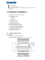
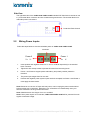
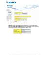
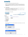
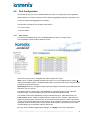
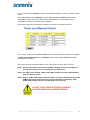
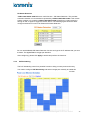
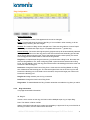
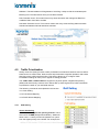
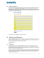
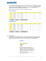
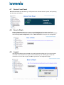
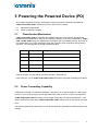
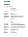
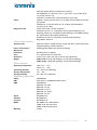
Korenix JetNet 3706/JetNet 3706f Industrial Web Managed PoE Plus Switch User Manual Version 2.2, 22-May-2008 www.korenix.com JetNet 3706/JetNet 3706f Industrial Web Managed PoE Plus Switch 1 Korenix JetNet 3706/JetNet 3706f Series Industrial Web Managed PoE Plus Switch User Manual Copyright Notice Copyright © 2007 Korenix Technology Co., Ltd. All rights reserved. Reproduction in any form or by any means without permission is prohibited. JetNet 3706/JetNet 3706f Industrial Web Managed PoE Plus Switch 2 Federal Communications Commission (FCC) Statement This equipment has been tested and found to comply with the limits for a Class A digital device, pursuant to Part 15 of the FCC Rules. These limits are designed to provide reasonable protection against harmful interference when the equipment is operated in a commercial environment. This equipment generates, uses, and can radiate radio frequency energy and, if not installed and used in accordance with the instruction manual, may cause harmful interference to radio communications. Operation of this equipment in a residential area is likely to cause harmful interference in which case the user will be required to correct the interference at his own expense. The user is cautioned that changes and modifications made to the equipment without approval of the manufacturer could void the user's authority to operate this equipment. JetNet 3706/JetNet 3706f Industrial Web Managed PoE Plus Switch 3 Index 1 Introduction 1.1 Overview ...............................................................................................1 1.2 Major Features ......................................................................................2 1.3 Package List..........................................................................................2 2 Hardware Installation 2.1 Hardware Introduction ...........................................................................3 2.2 Wiring Power Inputs ..............................................................................5 2.3 Wiring Earth Ground .............................................................................6 2.4 Wiring Fast Ethernet Ports ....................................................................6 2.5 Wiring Fast Ethernet Fiber Ports ...........................................................7 2.6 Connecting Powered Device (PD).........................................................7 2.7 DIN-Rail Mounting Installation...............................................................8 3 Preparation for Management 3.1 Preparation for Web Interface ...............................................................9 4 Feature Configuration 4.1 Basic Settings ..................................................................................... 11 4.2 Port Configuration ...............................................................................22 4.3 Power over Ethernet ...........................................................................23 4.4 Network Redundancy ..........................................................................27 4.5 Traffic Prioritization..............................................................................32 4.6 Monitoring and Diagnostic...................................................................34 4.7 Device Front Panel..............................................................................36 4.8 4.9 Save to Flash ......................................................................................36 Logout .................................................................................................36 5 Powering the Powered Device (PD) 5.1 Classification Mechanism....................................................................37 5.2 Power Forwarding Capability ..............................................................37 6 Appendix 6.1 Product Specifications .........................................................................39 6.2 Revision History ..................................................................................41 6.3 About Korenix......................................................................................42 1 Introduction Thank you for purchasing the JetNet 3706/JetNet 3706f and welcome to the Korenix JetNet 3706/JetNet 3706f Series Industrial Web Managed Power over Ethernet (PoE) Switch User Manual. The following topics are covered in this chapter: 1.1 Overview 1.2 Product Features 1.3 Package Checklist 1.1 Overview JetNet 3706 and JetNet 3706f are Industrial Web Managed Power over Ethernet (PoE) Switches, which include 4 Fast Ethernet RJ-45 ports with PoE injectors, 2 additional RJ-45 ports for JetNet 3706, and 2 additional Fast Ethernet fiber ports for JetNet 3706f. The additional ports can connect with a High-End Switch or a PC workstation. JetNet 3706/JetNet 3706f complies with IEEE802.3af PoE standards and IEEE802.3at pre-standards. The maximum power forwarding ability ranges from 13.53w to 29.52w, based on the voltage of the power input. JetNet 3706/ JetNet 3706f provides simple management interface via Web browser to feature more network performances. Network Redundancy To obtain superior network forwarding performance, JetNet 3706 /JetNet 3706f adopts QoS mechanism, Multiple Super Ring, and RSTP, which is in complies with IEEE802.1w-2004 edition to deliver a non-stop forwarding network. High Power PoE The excellent PoE power management features – IEEE 802.3af auto mode, IEEE 802.3af manual mode, Ultra power mode for 30W high power device and PoE scheduling control can enlarge your application and help saving power and more economic. The JetNet 3706/ JetNet3706f can apply with several of applications, such as PoE IP camera with PTZ function, Industrial I/O device with PoE enabled. High Power Forwarding Ability According to IEEE802.3af Power over Ethernet standards, it specifies a 15.4w power budget for PD systems. But, for some applications, 15.4w is not enough. For this purpose, JetNet 3706/JetNet 3706f provides 2 models of PoE powering mechanisms: IEEE802.3af, and High power pre-standard IEEE802.3at for high power budget. To recognize the PD classification ID, JetNet 3706/JetNet 3706f is equipped with a powerful micro-processor for detection, classification, powering and disconnecting purposes. JetNet 3706/JetNet 3706f automatically powers the PD with a different PD classification ID. It can deliver a maximum of 80W @ 45℃ output with a DC 55V power input for ID number 4. For the IEEE802.3af standard PD, JetNet 3706/JetNet 3706f also supports a maximum of 61.4W power forwarding ability with DC 48V power. JetNet 3706/JetNet 3706f Industrial Web Managed PoE Plus Switch 1 DC24V /48V PoE System For use with a DC 24V power source system, JetNet 3706/JetNet 3706f is equipped with a dual-mode PoE powering mechanism which detects power voltage input in order to execute the most beneficial powering and disconnecting process. This feature is suitable for transportation systems or any applications without a DC 48V power source. Also, JetNet 3706/JetNet 3706f will calculate its power consumption using output current and voltage, and will execute power budget limit protection. Forced Powering Ability When set PoE operation mode to forced mode, JetNet 3706/JetNet 3706f will directly deliver power even there is no Ethnernet cable plugged. With this ability, the powered device which doesn’t follow IEEE802.3af could also be drivered power. Quality of Service with WRR In order to obtain superior transmission performance,JetNet3706/JetNet3706f enables QoS function with 8:4:2:1 WRR forwarding mechanism. This feature ensures that real-time services can be processed with high priority and without forwarding delays. . 1.2 Major Features Korenix JetNet 3706 and JetNet 3706f have the following features: Four 10/100TX with PoE injector function Two 10/100TX ports with Auto MDI/MDI-X function (JetNet 3706) Two 100Mbps fiber ports (JetNet 3706f) In compliance with IEEE802.3af and IEEE802.3at pre-standards Supports Web browser and JetView management interface Patented Multiple Ring (MSR), Recovery time < 5ms IEEE 802.1d -2004 edittion Rapid Spanning Tree PoE power limiting and scheduling control Active Link Partner Live Detect (LPLD) function IEEE 802.1p Class of Service and DSCP DiffServ QoS QoS supports Tage based, port and IPv4 ToS End-Point PoE architecture, powered through conductors 4,5,7,8. Auto-Detect Power Source Voltage DC 24v or 48V Over-current/Cable short protection IP31 Aluminum housing for heightened heat radiation Redundant Power input DC 24/48V by Terminal Block -10~60°C (14~140°F) operating temperature 1.2KV Hi-pot testing passed (IEEE standard compliance) Note Detailed specifications are listed in Appendix 6.1 1.3 Package List Korenix JetNet 3706/JetNet 3706f ships with the following items: One Industrial PoE switch (JetNet 3706 or JetNet3706f) One DIN-Rail clip One wall mount plate and screws JetNet 3706/JetNet 3706f Industrial Web Managed PoE Plus Switch 2 CD user manual Quick Installation Guide If any of the above items are missing or damaged, please contact your local sales representative. 2 Hardware Installation The following topics are covered in this chapter: 2.1 Hardware Introduction Dimensions Panel Layout Bottom View 2.2 Wiring Power Inputs 2.3 Wiring Earth Ground 2.4 Wiring Fast Ethernet Ports 2.5 Wiring Fast Ethernet Fiber Ports 2.6 Connecting Powered Device (PD) 2.7 Powering the Powered Device (PD) 2.8 DIN-Rail Mounting Installation 2.9 Wall Mount Installation 2.1 Hardware Introduction Dimensions The dimensions of JetNet 3706/3706f are: 174.8mmW x 46.5mmH x 136mmD (6.82in W x 1.81in H x 5.30in D) JetNet 3706/JetNet 3706f Industrial Web Managed PoE Plus Switch 3 Mylar Layout There is one Mylar that is on the top panel of the JetNet PoE Switch. It includes 4 LEDs for system alarm, system power status, and RingMaster. There are 10 LEDs for port operating status. For detailed information, please check the following figure. JetNet 3706 Mylar layout JetNet 3706f Mylar layout Port Layout JetNet 3706 includes 4-Port 10/100TX that include embedded 4-Port PoE injection function in ports #1 ~#4 and 2 additional RJ-45 for JetNet 3706 (fiber for JetNet 3706f) for uplink functionality. See the following figures. JetNet 3706 JetNet 3706f JetNet 3706/JetNet 3706f Industrial Web Managed PoE Plus Switch 4 Side View The right-side view of the JetNet 3706/ JetNet 3706f Industrial PoE Plus Switch consists of one 6 –pin terminal block connector and one chassis earth ground screw. The terminal block is for redundant power connections. Protective Earth Ground 2.2 Wiring Power Inputs Follow the steps below to wire the redundant power of JetNet 3706/ JetNet 3706f. Not Used Power 2 V+ V1. Power 1 V+ V- Insert positive and negative wires into V+ and V- contacts respectively in the terminal block connector 2. Tighten the wire-clamp screws to prevent DC wires from becoming loose. 3. Power 1 and Power 2 support power redundancy and polarity reverse protection functions. 4. The power input ranges from DC 24~55V. 5. Positive and negative power system inputs are both accepted, but Power 1 and Power 2 must apply the same mode. Note Please be sure to turn off input and load power, and to unplug the power terminal block before making wire connections. Otherwise, your screwdriver can inadvertently short your terminal connections to the grounded enclosure. Note Suitable electric wire ranges from 12 to 24 AWG. Note If the 2 power inputs are connected, JetNet 3706/JetNet 3706f will be powered from the highest connected voltage. JetNet 3706/JetNet 3706f Industrial Web Managed PoE Plus Switch 5 2.3 Wiring Earth Ground To make sure data transmission is working properly, the Chassis Ground must be connected to the protective earth. Note All line-to-ground transient protection circuitry will be disabled if chassis ground is not connected with the protective earth. To ensure the system will not be damaged by noise or any electrical shock, we suggest making a direct connection with JetNet 3706/JetNet 3706f and Earth Ground to avoid system damage from electrical static discharge. On the right-side of JetNet 3706/JetNet 3706f , there is one earth ground screw. Loosen the earth ground screw with a screwdriver and tighten the screw after the earth ground wire is connected. 2.4 Wiring Fast Ethernet Ports JetNet 3706/JetNet 3706f is equipped 4 Power over Ethernet (PoE ) injectors with 30w forwarding capability in ports 1~4. The fast Ethernet ports support 10Base-T and 100Base-TX, full or half duplex modes. All of the fast Ethernet ports auto-detect signals from connected devices to negotiate link speed and duplex mode. Auto MDI/MDIX allows users to connect to another switch, hub or workstation without changing straight-through or crossover cables. JetNet 3706f has 2 100Mbps fiber ports for multi-mode or single-mode fiber. Note that crossover cables simply cross-connect the transmit lines at each end to the received lines at the opposite end. Straight-through Cabling Schematic Crossover Cabling Schematic Note Ethernet cables use pins 1, 2, 3, and 6 of an 8-pin RJ-45 connector. The signals of these pins are converted by the automatic MDI-X function as shown in the table below: Pin MDI-X Signals MDI Signals 1 RD+ TD+ 2 RD- TD- 3 TD+ RD+ 6 TD- RD- Connect one end of an Ethernet cable into any switch port and connect the other end to your attached device. The LINK LED will light up when the cable is connected correctly. Refer to the LED Indicators section for descriptions of each LED indicator. Always make sure that the cables connecting the switch and all attached devices (e.g. switch, hub, or workstation) are less than 100 meters (328 feet). JetNet 3706/JetNet 3706f Industrial Web Managed PoE Plus Switch 6 The wiring cable types are as follows: 10Base-T: 4 Pair UTP/STP Cat 3, 5e, 6 cable, EIA/TIA-568-B.2 100-ohm (up to100m) 100Base-TX: 4 Pair UTP/STP Cat. 5e, 6 cable, EIA/TIA-568-B.2 100-ohm (up to 100m) 2.5 Wiring Fast Ethernet Fiber Ports JetNet 3706f includes 2 fiber ports for Fast Ethernet Fiber uplink to other devices that are compatible with Fast Ethernet Fiber. JetNet 3706f supports multi-mode 2km (JetNet 3706f-m) or single-mode 30km (JetNet 3706f-s) for variable link distances. Make sure the fiber port on the end device is the same as your JetNet 3706f. The following table is the fiber transceiver that JetNet 3706f is equipped with. Model Fiber (um) JetNet Multi-mode Connecter Wavelength(um) TXPwr(min) TxPwr(Max) RxPwr(Min) 3706f-m 50~62.5/125 JetNet Single-mode 3706f-s 8~10/125 RxPwr(Max) LinkBudg(dBm) SC 1310nm -20dBm -14dBm -31dBm 0dBm 11dBm SC 1310nm -15dBm -8dBm -34dBm -8dBm 19dBm Distance(km) 2Km/5Km Note 30km Note The IEEE standard suggests that the available transmission distance is 2KM for 62.5/125um fiber optical cable in 1310nm wave length. Actually, the attenuation of multi-mode 62.5/125um optical fiber cable is 1.5dBm/KM and the maximum link distance can be up to 4~5km 2.6 Connecting Powered Device (PD) Ports 1~4 are equipped with PoE injectors that are in compliance with IEEE802.3af standards for 15.4w forwarding capability and 30w High power for IEEE802.3at pre-standards. JetNet 3706/JetNet 3706f follows the IEEE802.3af Alternative B mode connector assignments. The following table shows pin assignments for alternative A and B for the Power Sourcing Equipment (PSE). Conductor Alternative A (MDI-X) Alternative A (MDI) 1 Rx & Negative Vport TX & Positive Vport 2 Rx & Negative Vport TX & Positive Vport 3 TX & Positive Vport Rx & Negative port Alternative B (All) 4 Positive Vport 5 Positive Vport 6 TX & Positive Vport Rx & Negative Vport 7 Negative Vport 8 Negative Vport Pin assignment of PSE Make sure the twisted pair cable is bound with the standard RJ-45 pin, especially pins 4, 5, 7 and 8. If the RJ-45 is bound with the wrong RJ-45 conductors, JetNet 3706/JetNet 3706f will not recognize the PD and will forward DC 48V power to the PD, since the switch follows the Alternative B mode. In the IEEE 802.3af standard documents, it indicates that the PD should support mode A and B and only receive power from either mode A or mode B. JetNet 3706/JetNet 3706f Industrial Web Managed PoE Plus Switch 7 The following table shows the RJ-45 pin out for the PD. PD Pin out Conductor Mode A 1 Positive Vport, Negative Vport 2 Positive Vport, Negative Vport 3 Negative Vport, Positive Vport Mode B 4 Positive Vport, Negative Vport 5 Positive Vport, Negative Vport 6 Negative Vport,Positive Vport 7 Negative Vport, Positive Vport 8 Negative Vport,Positive Vport Notes Before installing the Powered Device (PD); please ensure that the PD pin assignment follows IEEE802.3af PD standards. There are some IEEE802.3af pre-standards stating that the PD can only accept mode A for power. In the IEEE802.3af standards, it indicates that the PD could be powered by either Mode A or Mode B. Caution: The PoE port of JetNet 3706/3706f should not make connection to Ethernet network with outside plant routing includeing campus, due the lighting strike may damage the system through the power system. 2.7 DIN-Rail Mounting Installation There are 2 DIN-Rail Clips in each unit box. Each set of DIN Rail clips include 4 screws and 2 clips. If the DIN-Rail set is missing, please contact a Korenix distributor for help. Use the screws to attach the DIN-Rail clip to the wall-mount plate included Wall Mount Installation Follow the steps below to install JetNet 3706/JetNet 3706f with its included wall mount plate. Use the hook holes at the corners of the wall mount plate to hang JetNet 3706/JetNet 3706f on the wall. Wall Mount plate and screws. JetNet 3706/JetNet 3706f Industrial Web Managed PoE Plus Switch 8 3 Preparation for Management The Korenix JetNet 3706/ JetNet 3706f provides Web browser configure interface. You just need to know the device’s IP address and you can remotely connect to its embedded HTTP web pages. The following topic are covered in this chapter: 3.1 Preparation for Web Interface 3.1 Preparation for Web Interface The JetNet 3706/ JetNet 3706f provides HTTP Web Interface for web management. 3.1.1 Web Interface The Korenix web management page uses JavaApplet. This allows you to use a standard Web browser such as Microsoft Internet Explorer or Mozilla FireFox to configure the switch from anywhere while connected to the network. Before you attempt to use the embedded web interface to manage switch operation, verify that your JetNet 3706/ JetNet 3706f Industrial Ethernet Switch is properly installed on your network and that every PC on the network can access the switch via Web browser. 1. Verify that your network interface card (NIC) is operational, and that your operating system supports TCP/IP protocol. 2. Wire the DC power to the switch and connect your switch to your computer. 3. Make sure that the switch default IP address is 192.168.10.1. 4. Change your computer IP address to 192.168.10.2 or another IP address in the 192.168.10.x subnet (Network Mask: 255.255.255.0). 5. Switch to DOS command mode and ping 192.168.10.1 to verify a normal response time. 6. Launch a web browser (Internet Explorer or Mozilla FireFox) on your PC. 7. Type http://192.168.10.1 (or the IP address of the switch) into the Web address window. Press Enter. 8. Key in the username and password. The default username and password are admin. 9. Click OK. The welcome page of the web-based management interface will now appear. JetNet 3706/JetNet 3706f Industrial Web Managed PoE Plus Switch 9 10. Once you enter the web-based management interface, you can change the JetNet 3706/ JetNet 3706f’s IP address to fit your network environment. Note 1: Internet Explorer Version 5.0 or later does not allow Java applets to open sockets by default. Users must directly modify the browser settings to selectively enable Java applets in order to use network ports. Note 2: The Web UI connection session of JetNet 3706/JetNet 3706f will logout automatically if you do not input anything after 30 seconds. Re-login if this occurs. JetNet 3706/JetNet 3706f Industrial Web Managed PoE Plus Switch 10 4 Feature Configuration This chapter explains how to configure the JetNet 3706/JetNet 3706f software and its features. The following topics are covered in this chapter: 4.1 Basic Settings 4.2 Port Configuration 4.3 Power over Ethernet 4.4 Network Redundancy 4.5 Traffic Prioritization 4.6 Monitor and Diag 4.7 Device Front Panel 4.8 Save to Flash 4.9 Logout 4.1 Basic Settings This section provides you with instructions on how to configure switch information, set the IP address, and configure the username and password of the system. It also allows you to upgrade the firmware, backup and restore a configuration, reload the system to factory default, and reboot the system. The following is included in this section: 4.1.1 Switch Setting 4.1.2 Admin Password 4.1.3 IP Configuration 4.1.4 Time Setting 4.1.5 Backup and Restore 4.1.6 Firmware Upgrade 4.1.7 Factory Default 4.1.8 System Reboot JetNet 3706/JetNet 3706f Industrial Web Managed PoE Plus Switch 11 4.1.1 System The following figure is the Web UI for System. Figure 4.1.1-1 System Description: View a description of the system. JetNet 3706 / JetNet 3706 f Industrial Management Ethernet Switch is the name of this product. Firmware Version: Display the firmware version installed on this device. MAC Address: Display the unique hardware address (MAC address) assigned by the manufacturer. 4.1.2 Admin Password You can change the username and password to enhance security The following figure is the Web UI for Admin Password Username: Key in a new username. The default setting is admin. Password: Key in a new password. The default setting is admin. Confirm Password: Re-enter the new password to confirm it. Once you finish configuring the settings, click Apply to apply your configuration. Note: Always remember to select Save to save your settings. Otherwise, the settings you made will be lost when the switch is powered off. JetNet 3706/JetNet 3706f Industrial Web Managed PoE Plus Switch 12 The following figure is the popup alert window when the incorrect username is entered. 4.1.3 IP Configuration This function allows user to configure the switch’s IP address settings. DHCP Client: Enable or Disable DHCP Client function. When DHCP Client function is enabled, an IP address will be assigned to the switch from the network’s DHCP server. In this mode, the default IP address will be replaced by the one assigned by the DHCP server. If DHCP Client is disabled, then the IP address that you specified will be used instead. IP Address: You can assign the IP address reserved by your network for your JetNet 3706 / JetNet 3706f. If DHCP Client function is enabled, you don’t need to assign an IP address, as it will be overwritten by the DHCP server. The default IP address is 192.168.10.1. Subnet Mask: Assign the subnet mask for the IP address. If DHCP Client function is enabled, you don’t need to assign the subnet mask. The default Subnet Mask is 255.255.255.0. Gateway: Assign the gateway for the switch. The default gateway is 192.168.10.254. Once you finish configuring the settings, click Apply to apply your configuration. 4.1.4 Time Setting Time Setting source allow user to set the time by manually or through NTP server. It also provide time synchronize from PC. Network Time Protocol (NTP) is used to synchronize computer clocks on the internet. You can configure NTP settings here to synchronize the clocks of several switches on the network. JetNet 3706/JetNet 3706f also provide Daylight Saving function. JetNet 3706/JetNet 3706f Industrial Web Managed PoE Plus Switch 13 Manual Setting: User can select Manual setting to change time as user want and also click the icon “Get Time From PC” to sync time from your PC. NTP client: Select the Time Setting Source to NTP client can let device enable the NTP client.It allow JetNet 3706 / JetNet3706f get time from 2 different NTP servers. The system will send request packet to acquire current time from the NTP server. JetNet 3706/JetNet 3706f Industrial Web Managed PoE Plus Switch 14 Time zone: Select the time zone where the switch is located. For your reference, the following table lists the time zones of different locations. The default time zone is GMT (Greenwich Mean Time). Switch(config)# clock timezone 01 (GMT-12:00) Eniwetok, Kwajalein 02 (GMT-11:00) Midway Island, Samoa 03 (GMT-10:00) Hawaii 04 (GMT-09:00) Alaska 05 (GMT-08:00) Pacific Time (US & Canada) , Tijuana 06 (GMT-07:00) Arizona 07 (GMT-07:00) Mountain Time (US & Canada) 08 (GMT-06:00) Central America 09 (GMT-06:00) Central Time (US & Canada) 10 (GMT-06:00) Mexico City 11 (GMT-06:00) Saskatchewan 12 (GMT-05:00) Bogota, Lima, Quito 13 (GMT-05:00) Eastern Time (US & Canada) 14 (GMT-05:00) Indiana (East) 15 (GMT-04:00) Atlantic Time (Canada) 16 (GMT-04:00) Caracas, La Paz 17 (GMT-04:00) Santiago 18 (GMT-03:00) NewFoundland 19 (GMT-03:00) Brasilia 20 (GMT-03:00) Buenos Aires, Georgetown 21 (GMT-03:00) Greenland 22 (GMT-02:00) Mid-Atlantic 23 (GMT-01:00) Azores 24 (GMT-01:00) Cape Verde Is. 25 (GMT) Casablanca, Monrovia 26 (GMT) Greenwich Mean Time: Dublin, Edinburgh, Lisbon, London 27 (GMT+01:00) Amsterdam, Berlin, Bern, Rome, Stockholm, Vienna 28 (GMT+01:00) Belgrade, Bratislava, Budapest, Ljubljana, Prague 29 (GMT+01:00) Brussels, Copenhagen, Madrid, Paris 30 (GMT+01:00) Sarajevo, Skopje, Sofija, Vilnius, Warsaw, Zagreb 31 (GMT+01:00) West Central Africa 32 (GMT+02:00) Athens, Istanbul, Minsk 33 (GMT+02:00) Bucharest 34 (GMT+02:00) Cairo 35 (GMT+02:00) Harare, Pretoria 36 (GMT+02:00) Helsinki, Riga, Tallinn 37 (GMT+02:00) Jerusalem 38 (GMT+03:00) Baghdad 39 (GMT+03:00) Kuwait, Riyadh 40 (GMT+03:00) Moscow, St. Petersburg, Volgograd 41 (GMT+03:00) Nairobi 42 (GMT+03:30) Tehran 43 (GMT+04:00) Abu Dhabi, Muscat 44 (GMT+04:00) Baku, Tbilisi, Yerevan 45 (GMT+04:30) Kabul 46 (GMT+05:00) Ekaterinburg 47 (GMT+05:00) Islamabad, Karachi, Tashkent 48 (GMT+05:30) Calcutta, Chennai, Mumbai, New Delhi 49 (GMT+05:45) Kathmandu 50 (GMT+06:00) Almaty, Novosibirsk JetNet 3706/JetNet 3706f Industrial Web Managed PoE Plus Switch 15 51 52 53 54 55 56 57 58 59 60 61 62 63 64 65 66 67 68 69 70 71 72 73 74 (GMT+06:00) Astana, Dhaka (GMT+06:00) Sri Jayawardenepura (GMT+06:30) Rangoon (GMT+07:00) Bangkok, Hanoi, Jakarta (GMT+07:00) Krasnoyarsk (GMT+08:00) Beijing, Chongqing, Hong Kong, Urumqi (GMT+08:00) Irkutsk, Ulaan Bataar (GMT+08:00) Kuala Lumpur, Singapore (GMT+08:00) Perth (GMT+08:00) Taipei (GMT+09:00) Osaka, Sapporo, Tokyo (GMT+09:00) Seoul (GMT+09:00) Yakutsk (GMT+09:30) Adelaide (GMT+09:30) Darwin (GMT+10:00) Brisbane (GMT+10:00) Canberra, Melbourne, Sydney (GMT+10:00) Guam, Port Moresby (GMT+10:00) Hobart (GMT+10:00) Vladivostok (GMT+11:00) Magadan, Solomon Is., New Caledonia (GMT+12:00) Aukland, Wellington (GMT+12:00) Fiji, Kamchatka, Marshall Is. (GMT+13:00) Nuku'alofa Daylight Saving Time: To set when Daylight Saving Time start and end, During the Daylight Saving Time, the device’s time is one hour earlier than the actual time. Once you have finished the configuration, click Apply to apply your configuration. 4.1.5 Backup and Restore With the Backup command, you can save current configuration files saved in the switch’s flash to the admin PC or TFTP server. This will allow you to go to the Restore command later, in order to restore the configuration file back to the switch. Before you restore the configuration file, you must place the backup configuration file into the PC or TFTP server. The switch will then download this file back to the flash. There are 2 modes for users to backup/restore the configuration file, Local File mode and TFTP Server mode. Local File mode: In this mode, the switch acts as the file server. Users can browse the target folder and then type in the file name to backup the configuration. Users can also browse the target folder and select existing configuration files to restore the configuration back to the switch. TFTP Server mode: In this mode, the switch acts as TFTP client. Before you do so, make sure that your TFTP server is ready. Then type in the IP address of the TFTP Server and backup configuration file name. This mode can be used in both CLI and Web UI. TFTP Server IP Address: Key in the IP address of your TFTP Server here. JetNet 3706/JetNet 3706f Industrial Web Managed PoE Plus Switch 16 Backup/Restore File Name: the filename of the configuration file Configuration File: The configuration file of the switch is a text file. You can open it with Microsoft Word or any program that can read .txt files, modify the file, add/remove configuration settings, and then restore it back on to the switch. Startup Configuration File: After you have saved the running-config to flash, the new settings will be updated after a power cycle. You can use show startup-config to view it in the CLI. The Backup command can only backup such configuration files to your PC or TFTP server. Technical Tip: Default Configuration File: The switch provides the default configuration file in the system. You can use the Reset button, Reload command to reset the system. Running Configuration File: The switch’s CLI allows you to view the latest settings running on the system. The information shown here are the settings you set up but notfinish saved to flash.and Theconfiguring settings notthe yetsettings, saved toclick flash not work after a power Onhave ce you selecting onwill Backup or Restore to run the cycle. You can use show running-config to view it in the CLI. process. The following figure is the Main UI for Backup & Restore The following figure is the WEB UI for Backup/Restore Configuration - Local File mode. JetNet 3706/JetNet 3706f Industrial Web Managed PoE Plus Switch 17 Click on the Folder icon to select the target file you want to backup/restore. Note: The folders of the path to the target file do not allow you to input space key. The following figure is the Web UI for Backup/Restore Configuration - TFTP Server mode Type in the IP address of TFTP Server IP. Then click on Backup/Restore. 4.1.6 Firmware Upgrade In this section, you can update the switch with the latest firmware. Korenix provides the latest firmware on Web site (www.korenix.com). New firmware may include new features, bug fixes or other software changes. The Web site also provides release notes for the update as well. We suggest you use the latest firmware before installing the switch. Note: The system will automatically reboot after you finish upgrading the new firmware. Please inform all attached users before doing this. The following figure is the Web Main UI for Firmware Upgrade. There are 2 modes for users to upgrade the firmware, Local File mode and TFTP Server mode. Local File mode: In this mode, the switch acts as the file server. Users can browse the target folder and then type in the file name to upgrade the firmware. Users can also browse the target folder and select the existing firmware file to upgrade the switch. TFTP Server mode: In this mode, the switch acts as the TFTP client. Before you do so, make sure that your TFTP server is ready. Then, type in the TFTP Server IP address. TFTP Server IP Address: Key in the IP address of your TFTP Server here. JetNet 3706/JetNet 3706f Industrial Web Managed PoE Plus Switch 18 Firmware File Name: View the file name of the new firmware. The UI also shows you the version and built date of current firmware. Please check the version number after you reboot the switch. The following Web UI is for Firmware Upgrade - Local File mode. Click on the Folder icon to select the target file you want to backup/restore. The following Web UI is for Firmware Upgrade – TFTP Server mode. Type in the IP address of the TFTP Server and the Firmware File Name. Then click Upgrade to start the process. After finishing the transmission of the firmware, the system will copy the firmware file and replace the firmware in the flash. JetNet 3706/JetNet 3706f Industrial Web Managed PoE Plus Switch 19 4.1.7 Factory Default In this section, you can reset all the configurations of the switch to its default settings. By clicking on Reset the system will reset all configurations to its default settings. The system will show you a popup message window after running this command. Default settings will be in effect after rebooting the switch. The Web UI figure for Reset to Default The following figure is the popup alert screen to confirm the command. Click on Yes to reset the system. The following UI is a popup message screen to show you that the reset is complete. Click OK to close the screen. Then go to the Reboot page to reboot the switch. JetNet 3706/JetNet 3706f Industrial Web Managed PoE Plus Switch 20 Click OK. The system will then automatically reboot the device. Note: If you have already configured the IP of your device to another IP address; when you use this command through CLI and Web UI, our software will not reset the IP address to the default IP. The system will maintain the IP address so that you can still connect to the switch via the network. 4.1.8 System Reboot System Reboot allows you to reboot the device. Some of the feature changes require you to reboot the system. Click on Reboot to reboot your device. Note: Remember to click on the Save button to save your settings. Otherwise, the settings you made will be gone once the switch is powered off. Below is the Main screen for Reboot Below is the popup alert screen to request confirmation for the Switch Reboot. Click on Yes to reboot the switch. The popup message screen below appears when rebooting the switch. JetNet 3706/JetNet 3706f Industrial Web Managed PoE Plus Switch 21 4.2 Port Configuration This section shows you how to enable/disable port state, or configure port auto-negotiation, speed, duplex, flow control, rate limit control and port aggregation settings. It also allows you to view port status and aggregation information. The following commands are covered in this section: 4.2.1 Port Control 4.2.2 Port Status 4.2.1 Port Control Port Control commands allow you to enable/disable port state, or configure port auto-negotiation, speed, duplex, and flow control. Select the port you want to configure and make changes to the port. State column: Enable or disable the state of this port. Once you disable the port, it stops to linking and forwarding traffic. The default setting when you receive the device is Enable, which means all the ports are working. Speed/Duplex column: Configure the port speed and duplex mode of this port. Below are the selections you can choose: Fast Ethernet Port 1~6 (fa1~fa6) : Auto Negotiation, 10M Full Duplex(10 Full), 10M Half Duplex(10 Half), 100M Full Duplex(100 Full) and 100M Half Duplex(100 Half). The default mode is Auto Negotiation mode for fast Ethernet port, 100M full for fiber port Flow Control column: Enable or disable the flow control function. “Enable” means that you need to activate the flow control function of the remote network device in order to let the flow control of that corresponding port on the switch to work. “Disable” means that you do not need to activate the flow control function of the remote network device, as the flow control of that corresponding port on the switch will work either way. Once you have finished configuring the settings, click Apply to save the configuration. JetNet 3706/JetNet 3706f Industrial Web Managed PoE Plus Switch 22 Technical Tips: If both ends are going at different speeds, they will not link to each other. If both ends are in different duplex modes, they will be connected by half mode. 4.2.2 Port Status Port Status shows you the current port status. A description of each column is as follows: Port: Port interface number. Type: 100BASE -> Fast Ethernet port. Link: Link status. Up -> Link UP. Down -> Link Down. State: Enable -> State is enabled. Disable -> The port is disable by user configured. Speed/Duplex: Current working status of the port. Flow Control: The state of the flow control. 4.3 Power over Ethernet Power over Ethernet is one of the key features of JetNet 3706/ JetNet 3706f. It is in compliance with IEEE 802.3af standards and supports 30w High power forwarding capability. JetNet 3706/JetNet 3706f adopts 4-Port PoE injectors in port 1 to port 4, each port with the ability to deliver a 0.615mA current. The following commands are included in this section: 4.3.1 PoE Control 4.3.2 PoE Scheduling 4.3.3 PoE Status 4.3.1 PoE Control Pull down the Powering Mode column can change the Powering Mode to IEEE 802.3af or forced mode. When the column is IEEE 802.3af, if and only if the PD is follow IEEE 802.3af then JetNet3706 /JetNet 3706f could deliver power. But if the Powering Mode changes to forced mode, once the PoE mode is enabled, the port will directly deliver power even there is no Ethernet cable plugged. Please be careful when using forced mode. JetNet 3706/JetNet 3706f Industrial Web Managed PoE Plus Switch 23 You can pull down the PoE state column to enable/disable ports, or set it to schedule control mode. The Power Mode provides Standard mode for IEEE 802.3af PD, Manual mode for user configuration of the power limit to IEEE 802.3af standard PD, or Ultra mode for user configuration to perform at the 30w power limitation. The following figure shows the Web UI interface for Power over Ethernet Control. You can type a value into the Power Limit column to set the limitation of power consumption. If JetNet 3706/JetNet 3706f is set to Standard mode, it will execute IEEE 802.3af power limiting rule by PD class. The maximum value of Manual mode is 15.4w; Ultra mode is 20w for each PoE port. Note 1: Please pay attention when Powering Mode changed to forced moed Because directly delivering power may damage the non-PoE device. Note 2: For high power feeding, JetNet 3706/ JetNet 3706f must power with DC 55V to deliver maximum power. Note 3: Ensure JetNet 3706/JetNet 3706f mounted on well heat radiated panel and under 60℃ environment during PoE port progress High Power forwarding . High Power PoE Feeding will cause system temperature rised up. . DO NOT TOUCH DEVICE SURFACE DURING PoE PROGRESS HIGH POWER FEEDING JetNet 3706/JetNet 3706f Industrial Web Managed PoE Plus Switch 24 PD Status Detection JetNet 3706/JetNet 3706f delivers a useful function – PD Status Detection. This provides automatic detection of a remote device powered by JetNet 3706/JetNet 3706f. If the remote system crashes or is unstable, JetNet 3706/JetNet 3706f will perform a system reboot by turning off and on again to trigger the remote device. The following figure shows the Web configure interface for Power over Ethernet PD Status Detection. You can enable/disable PD Status Detection function and type in the IP address that you want to detect. The Cycle Time is the gap per detection. After configuring, please click Apply to enable and perform the functions. 4.3.2 PoE Scheduling The PoE Scheduling control is a powerful function to help you save power and money. You need to configure PoE Scheduling and select a target port manually to enable this function. JetNet 3706/JetNet 3706f Industrial Web Managed PoE Plus Switch 25 4.3.3 PoE Status The PoE Status page shows the operating status of each PoE Port. The information includes Detection status, current PD class, Power Consumption, and delivered Voltage and Current. JetNet 3706/JetNet 3706f Industrial Web Managed PoE Plus Switch 26 4.4 Network Redundancy It is critical for industrial applications for networks to continue working non-stop. JetNet 3706 / JetNet 3706f supports standard RSTP, Multiple Super Ring,and Legacy Super Ring Client modes. Multiple Super Ring (MSR) technology is Korenix’s 3rd generation Ring redundancy technology. This is patented and protected by Korenix and is used in countries all over the world. MSR ranks the fastest recovery time (both failover and restore time) in the world, less than 5 milliseconds in 10/100 Megabit Copper Ring topology. To backward compatible with the Legacy Super Ring technology implemented in JetNet 4000/4500 switches, JetNet 3706 / JetNet 3706f also supports Super Ring Client mode. The Super Ring ports can pass through Super Ring control packets extremely well and works with Super Ring. Besides Korenix ring technology, JetNet 3706 / JetNet3706f also supports IEEE 802.1D-2004 version Rapid Spanning Tree Protocol (RSTP). The new version of RSTP standard includes IEEE 802.1D-1998 STP, 802.1w RSTP. The following commands are included in this section: 4.4.1 RSTP 4.4.2 RSTP Info 4.4.3 Multiple Super Ring 4.4.4 Ring Info 4.4.1 RSTP RSTP stands for Rapid Spanning Tree Protocol. If a switch has more than one path to a destination, it will lead to message loops that can generate broadcast storms and quickly bog down a network. The spanning tree was created to combat the negative effects of message loops in switched networks. A spanning tree uses a spanning tree algorithm (STA) to automatically sense whether a switch has more than one way to communicate with a node. It will then select the best path (primary), and block the other path(s). It will also keep track of the blocked path(s) in case the primary path fails. Spanning Tree Protocol (STP) introduced a standard method to accomplish this. It is specified in IEEE 802.1D-1998. Later, Rapid Spanning Tree Protocol (RSTP) was adopted and represents the evolution of STP, providing for a much faster spanning tree convergence after a topology change. This is specified in IEEE 802.1w. In 2004, IEEE 802.1w was included into the IEEE 802.1D-2004 version. This switch supports both RSTP and STP (all switches that support RSTP are also backwards compatible with switches that support only STP). This page allows you to enable/disable RSTP, and configure the global setting and port settings. JetNet 3706/JetNet 3706f Industrial Web Managed PoE Plus Switch 27 RSTP Mode: You must first enable STP/RSTP mode before configuring any related parameters. Parameter settings required for both STP and RSTP are the same. Note that 802.1d refers to STP mode, while 802.1w refers to faster RSTP mode. Bridge Configuration Priority (0-61440): RSTP uses bridge ID to determine the root bridge, the bridge with the highest bridge ID becomes the root bridge. The bridge ID is composed of bridge priority and bridge MAC address. So that the bridge with the highest priority becomes the highest bridge ID. If all of the bridge IDs have the same priority, the bridge with the lowest MAC address will then become the root bridge. Note: The bridge priority value must be in multiples of 4096. A device with a lower number has a higher bridge priority. Ex: 4096 is higher than 32768. Max Age (6-40): Enter a value from 6 to 40 seconds here. This value represents the time that a bridge will wait without receiving Spanning Tree Protocol configuration messages before attempting to reconfigure. If JetNet 3706 / JetNet 3706f is not the root bridge, and if it has not received a hello message from the root bridge in the amount of time equal to the Max Age, then JetNet 3706 / JetNet 3706f will reconfigure itself as a root bridge. Once two or more devices on the network are recognized as a root bridge, the devices will renegotiate to set up a new spanning tree topology. Hello Time (1-10): Enter a value from 1 to 10 seconds here. This is a periodic timer that drives the switch to send out a BPDU (Bridge Protocol Data Unit) packet to check current STP status. The root bridge of the spanning tree topology periodically sends out a “hello” message to other devices on the network to check if the topology is “healthy.” The “hello time” is the amount of time the root has waited in between sending hello messages. JetNet 3706/JetNet 3706f Industrial Web Managed PoE Plus Switch 28 Forward Delay Time (4-30): Enter a value between 4 and 30 seconds. This value is the time that a port waits before changing from Spanning Tree Protocol learning and listening states to forwarding state. This is the amount of time JetNet 3706 / JetNet 3706f will wait before checking to see if it should be changed to a different state. Once you have completed your configuration, click on Apply to apply your settings. Note: You must observe the following rules to configure Hello Time, Forwarding Delay, and Max Age parameters. 2 × (Forward Delay Time – 1 sec) >= Max Age Time >= 2 × (Hello Time value + 1 sec) Port Configuration Select the port you want to configure; you will be able to view the current settings and status of the port. Path Cost: Enter a number between 1 and 200,000,000. This value represents the “cost” of the path to the other bridge from the transmitting bridge at the specified port. Priority: Enter a value between 0 and 240 using multiples of 16. This is the value that decides which port should be blocked by priority in a LAN. Admin P2P: Some of the rapid state transitions that are possible within RSTP depend upon whether the port of concern can only be connected to another bridge (i.e. it is served by a point-to-point LAN segment), or if it can be connected to two or more bridges (i.e. it is served by a shared-medium LAN segment). This function allows P2P status of the link to be manipulated administratively. Auto means to auto select P2P or Share mode. P2P means P2P is enabled, while Share means P2P is disabled. Admin Edge: A port directly connected to the end stations cannot create a bridging loop in the network. To configure this port as an edge port, set the port to the Enable state. When the non-bridge device connects an admin edge port, this port will be in blocking state and turn to forwarding state in 4 seconds. Once you have finished your configuration, click Apply to save your settings. JetNet 3706/JetNet 3706f Industrial Web Managed PoE Plus Switch 29 4.4.2 RSTP Info This page allows you to see the information of the root switch and port status. Root Information: You can see Root Bridge ID, Root Priority, Root Port, Root Path Cost and the Max Age, Hello Time and Forward Delay of BPDU sent from the root switch. Port Information: You can see port Role, Port State, Path Cost, Port Priority, Oper P2P mode and Oper edge port mode. 4.4.3 Multiple-super-ring (MSR) The most common industrial network redundancy is to form a ring or loop. Typically, the managed switches are connected in a series and the last switch is connected back to the first one. In such a connection, you can use Korenix Multiple super ring technology. Super Ring is Korenix’s 1st generation ring redundancy technology released with JetNet 4000/4500. Rapid Super Ring (RSR) is Korenix’s 2nd generation Ring redundancy technology. The Rapid Super Ring has an enhanced Ring Master selection and shorter recovery time. Mutilple Super Ring is the 3rd Korenix Ring technology. It is designed for more complex ring application and even more faster recovery time. These are patented and protected by Korenix and is used in countries all over the world. New Ring: To create a Multiple-super-ring. Just fill in the Ring ID which have a range from 0 to 31. If the name field is left blank, the name of this ring will automatically named with RingID. This page allows you to enable the settings for Multiple-super-ring. JetNet 3706/JetNet 3706f Industrial Web Managed PoE Plus Switch 30 Ring Configuration ID: Once a Ring is created, This appears and can not be changed. Name: This field will show the name of the Ring. If it is not filled in when creating, it will be automatically named by the rule “RingID”. Version: The version of Ring can be changed here. There are two modes to choose: Rapid Super Ring as default and Super ring for compatible with Korenix 1st general ring. Device Priority: The switch with highest priority (highest value) will be automatically selected as Ring Master. Then one of the ring ports in this switch will become forwarding port and the other one will become blocking port. If all of the switches have the same priority, the switch with the biggest MAC address will be selected as Ring Master. Ring Port1: In Rapid Super Ring environment, you should have 2 Ring Ports. No matter this switch is Ring Master or not, when configuring RSR, 2 ports should be selected to be Ring Ports. For Ring Master, one of the ring ports will become the forwarding port and the other one will become the blocking port. Path Cost: Change the Path Cost of Ring Port1. If this switch is the Ring Master of a Ring, then it determines the blocking port. The Port with higher Path Cost in the two ring Port will become the blocking port, If the Path Cost is the same, the port with larger port number will become the blocking port. Ring Port2: Assign another port for ring connection Path Cost: Change the Path Cost of Ring Port2 Ring status: To enable/disable the Ring. Please remember to enable the ring after you add it. 4.4.4 Ring Information This page shows MSR information. ID: Ring ID. Version: which version of this ring, this field could be Multiple super ring or Super Ring. Role: This Switch is RM or nonRM Status: If this field is Normal which means the redundancy is approved. If any one of the link in this Ring is broken, then the status will be Abnormal. JetNet 3706/JetNet 3706f Industrial Web Managed PoE Plus Switch 31 RM MAC: The MAC address of Ring Master of this Ring. It helps to find the redundant path. Blocking Port: This field shows which port of RM.is blocked. Role Transition Count: This means how many times this switch has changed its Role from nonRM to RM or from RM to nonRM. Role state Transition Count: This number means how many times the Ring status has been transformed between Normal and Abnormal state. 4.5 Traffic Prioritization Quality of Service (QoS) provides a traffic prioritization mechanism that allows users to deliver better service to certain flows. QoS can also help to alleviate congestion problems and ensure that high priority traffic is delivered first. This section allows you to configure Traffic Prioritization settings for each port in regards to setting priorities. The JetNet 3706 / JetNet 3706f QoS supports 4 physical queues, weighted fair queuing (WRR) and Strict Priority scheme, which follows 802.1p COS tag and IPv4 DSCP information to prioritize the traffic of your industrial network. The following commands are explained in this section: 4.5.1 QoS Setting 4.5.2 CoS-Queue Mapping 4.5.3 DSCP-Queue Mapping 4.5.1 QoS Setting Queue Scheduling Use an 8,4,2,1 weighted fair queuing scheme. This is also known as WRR (Weight Round Robin). JetNet will follow a 8:4:2:1 rate to process the packets in a queue from the highest priority to the lowest. For example, the JetNet 3706/JetNet 3706f Industrial Web Managed PoE Plus Switch 32 system will simultaneously process 8 packets with the highest priority in the queue, 4 packets with middle priority, 2 packets with low priority, and 1 packet with the lowest priority. Use a strict priority scheme. Packets with the highest priority in the queue will always be processed first. Port Setting The Priority column is to indicate the default port priority value for untagged or priority-tagged frames. When JetNet 3706 / JetNet 3706f receives the frames, it will assign the value to the priority. You can enable 0,1,2,3 to the port. The priority is directly mapping to queue id, queue 3 is the highest priority queue. Trust Mode: This indicates Queue Mapping types for you to select. CoS Only: Port priority will only follow CoS-Queue Mapping that you have assigned. DSCP Only: Port priority will only follow DSCP-Queue Mapping that you have assigned. CoS first: Port priority will follow CoS-Queue Mapping first, and then DSCP-Queue Mapping rule. DSCP first: Port priority will follow DSCP-Queue Mapping first, and then CoS-Queue Mapping rule. Port Based: The port priority will follow the queue priority that you have assigned. The default priority type is CoS Only. The system will provide a default CoS-Queue table that you can refer to for the next command. After configuring, press Apply to enable the settings. 4.5.2 CoS-Queue Mapping This area is where the user can set CoS values to the Physical Queue mapping table. Since the switch fabric of JetNet 3706 / JetNet3706f supports 4 physical queues (Lowest, Low, Middle and High), users should assign CoS value to the level of the physical queue. With the JetNet 3706 / JetNet 3706f users can easily assign the mapping table or follow suggestions from the 802.1p standard. Korenix uses 802.1p standards for its default values. You will find that the CoS values 1 and 2 are mapped to physical Queue 0 (lowest queue). CoS values 0 and 3 are mapped to physical Queue 1, (low/normal physical queue), CoS values 4 and 5 are mapped to physical Queue 2 (middle physical queue), and CoS values 6 and 7 are mapped to physical Queue 3 (highest physical queue). After configuring, press Apply to enable the settings. JetNet 3706/JetNet 3706f Industrial Web Managed PoE Plus Switch 33 4.5.3 DSCP-Queue Mapping This is where users can change DSCP values to a Physical Queue mapping table. Since the switch fabric of the JetNet 3706 / JetNet 3706f supports 4 physical queues, (lowest, low, middle and high), users should assign a DSCP value to the level of the physical queue. With the JetNet 3706 / JetNet 3706f users can easily change the mapping table to follow the upper layer 3 switch or routers’ DSCP setting. After configuring, press Apply to enable the settings. 4.6 Monitoring and Diagnostic JetNet 3706/JetNet 3706f provides port statistics function for you to monitor the status of the switch or create a diagnostic for you to check the problem when issues with the switch occur. The following commands are included in this section: 4.6.1 Port Statistics 4.6.2 Ping 4.6.1 Port Statistics On this page, you can view operational statistics for each port. The statistics that can be viewed include Link Type, Link State, Rx Good, Rx Bad, Tx Good, and Collision. Rx means the received packets while Tx means the transmitted packets. The statistics can just show Rx Good and Tx Good or Rx Bad and Collision. Note: If you see an increase in Bad or Collision counts, this may mean that your network cable is not connected correctly or the network performance of the port is poor. Please check your network cable, Network Interface Card connected to your device, the network application, or reallocate the network traffic. JetNet 3706/JetNet 3706f Industrial Web Managed PoE Plus Switch 34 Click on Clear Selected to reset the counts of the selected ports and on Clear All to reset the counts of all ports. Click on Reload to refresh the counts. Also, Click on Bad-Collision Mode to change counter mode to RxBad and TxCollisions mode and on Good Mode button to change counter mode to RxGood and TxGood mode. Note: If the mode is changed. The statistics counter will be reset to 0.. 4.6.2 Ping Utility This page provides Ping Utility for users to ping remote devices and to check whether the device is alive or not. Type the target IP address of the target device into Target IP. Click on Start to start the ping. After few seconds, you will see the results in the Result field. JetNet 3706/JetNet 3706f Industrial Web Managed PoE Plus Switch 35 4.7 Device Front Panel Device Front Panel provides Web type LED panel which indicates status of power, PoE powering and link status of Ethernet. 4.8 Save to Flash Save Configuration allows you to save any configuration you just made to the Flash. Powering off the switch without clicking on Save Configuration will cause loss of new settings. After selecting Save Configuration, click on Save to Flash to save your new configuration. 4.9 Logout The switch provides 2 logout methods. Your web connection will log out if you do not input a command for 30 seconds. The Logout command allows you to manually log out the web connection. Click on Yes to logout, and No to go back to the configuration page. JetNet 3706/JetNet 3706f Industrial Web Managed PoE Plus Switch 36 5 Powering the Powered Device (PD) This chapter describes powering, classification scheme and power forwarding capabilities of JetNet 3706/JetNet 3706f. The following are the topics for this chapter. 5.1 Classification Mechanism 5.2 Power Forwarding Capability 5.1 Classification Mechanism JetNet 3706/JetNet 3706f is compliant with IEEE802.3af Power over Ethernet standards and IEEE802.3at pre-standards for 30w power forwarding capability. A PD can be classified by JetNet 3706 / JetNet 3706f through the classification information that is provided by the PD. The intent of PD classification is to provide information about the maximum power required by the PD during operation. The following table is the PD classification table. Class ID Usage Range of Maximum Power used of PD 0 Default 0.44~12.95w 1 Optional 0.44~3.84w 2 Optional 4.83~6.49w 3 Optional 6.49~12.95w 4 Not Allowed Reserved for Future use (High Power) Class ID number 4 is reserved for the future standard – IEEE802.3at. If the class ID is 4, then JetNet 3706/JetNet 3706f will perform high-power forwarding procedures. 5.2 Power Forwarding Capability In IEEE802.3af Power over Ethernet standards, it specifies a 15.4w power budget for a PD system. However, 15.4w is not enough for some applications that need more than 15.4w. For this purpose, JetNet 3706/JetNet 3706f will execute power budget control based on the PD classification. It will deliver 120W power output when JetNet 3706/JetNet 3706f is attached to DC 55V power and class 4 PD. The following table shows calculations for PoE power forwarding capabilities at different power input voltages. JetNet 3706/JetNet 3706f Industrial Web Managed PoE Plus Switch 37 Power Input (V) PoE output (V) PoE Output ( I ) PoE Output Power (W) DC 24 DC 21 0.615A (Max) 13.53w (Max) DC 32 DC 29 0.615A (Max) 18.45w (Max) DC 48 DC 45 0.615A(Max) 28.29w (Max) DC 55 DC 52 0.615A (Max) 29.52w (Max) JetNet 3706/JetNet 3706f Industrial Web Managed PoE Plus Switch 38 6 Appendix 6.1 Product Specifications Technology Standard IEEE 802.3 10Base-T IEEE 802.3u 100Base-T IEEE 802.1p Class of Service IEEE 802.3af Power Over Ethernet IEEE 802.1d Spanning Tree IEEE 802.1w Rapid Spanning Tree Performance Switch Technology System Throughput MAC Address Packet Buffer Transfer performance Management interface Class of Service Quality of Service DHCP Timer Network Redundancy Firmware upgrade PoE Port Control Power Limit Control PoE Scheduling Control LPLD function Store and Forward Technology with 3.2Gbps wire-speed non-blocking Switch Fabric 1.785Mpps 2000 Embedded 1Mbits shared buffer 14,880pps for Ethernet and 148,800 for Fast Ethernet and transfer packet size from 64 to 1522Bytes. Embedded HTTP Server for Web Management and JetView IEEE802.1p class of service, 4 priority queues per port. Quality of Service determined by port, Tag and IPv4 Type of Service. Supports DHCP Client. Supports Network Time Protocol (NTP) to synchronize time from internet. Supports Multiple super ring function for network redundancy with 5~30 ms network recovery time; To inter-operate with other higher-level switches, JetNet3706 /JetNet3706f also compliant with IEEE802.1d 2004 edition for RSTP and STP. TFTP, HTTP, and JetView firmware upgrade. Supports user configure for PoE enable/disable. The control mode supports IEEE802.3af standard, Manual and Ultra mode for 30W Hi-power. The maximum deliver power on each PoE port is 12.915W@DC 24V input ~30W @ DC50V input with 0.615A current. Each PoE port would active and powering with different control rule and supports Weekly Scheduling by Hourly basis. The Link Partner Line Detect function (LPLD) is available on PoE ports. With the LPLD function, the PoE port can keep attached PD alive. Interface Number of Ports Connectors PoE Technology 4 x 10/100Base-TX with PoE Injector 3706: 2 x 10/100Base-TX ports 3706f: 2 x 100Base-FX 10/100TX: RJ-45 6-pin Terminal Block: 2 Redundant power End-Span wiring architecture PD classification detection, class ID 0~3 for IEEE802.3af standard, and JetNet 3706/JetNet 3706f Industrial Web Managed PoE Plus Switch 39 Cable Diagnostic LED 30W High power deliver procedures for class ID 4. Pin assignment: V+ (RJ-45 Pin 4,5), V- (RJ-45 Pin 7,8), TX (RJ-45 Pin 1,2), RX (RJ-45 Pin 3,6) Protection: Provides Over-current protection by PD class. 10Base-T: 4 Pair UTP/STP Cat 3, 5e, 6 cable, EIA/TIA-568-B.2 100-ohm (up to100m) 100Base-TX: 4 Pair UTP/STP Cat. 5e, 6 cable, EIA/TIA-568-B.2 100-ohm (up to 100m) Power LED: Power 1/Power 2 (Green) Fast Ethernet Port 1~4: Link(Green) /Activity (Green blinking), PoE Powering (Yellow on), PoE Detect (Yellow blinking), PoE Disable (Yellow off), PoE Powering fail (Yellow fast blinking) Fast Ethernet Port 5,6: Link(Green) /Activity (Green blinking) Ring Master: Green on Power Requirements System Power Power Consumption Mechanical Installation Case Dimension Weight Support Positive or negative power system with DC 24~55V power input range and polarity reverse protection. 8 Watts @ 48V (Maximum) without PD loading DIN-Rail mount or desktop IP-31 grade aluminum metal case 45.5 mm (H) x 185.3 mm (W) x 136 mm (D) without DIN JetNet 3706: 0.70 kg with package / 0.65 kg without package JetNet 3706f: 0.68 kg with package/ 0.64 kg without package Environmental Operating Temperature Operating Humidity Storage Temperature Storage Humidity 3706: -20℃ ~ 60℃ 3706f: -10℃ ~ 60℃ 5% ~ 90% non-condensing -40℃ ~ 80 ℃ 5%~ 90% non-condensing Regulatory Approvals Safety EMI EMS Shock Vibration Free Fall MTBF Warranty CE/EN60950 FCC Class A, CE/EN55022:2003,class A CE/EN55024 EN61000-4-2: ESD EN61000-4-3: RS EN61000-4-4: EFT EN61000-4-5: Surge EN61000-4-6: CS IEC60068-2-27 IEC60068-2-6 IEC60068-2-32 MIL-HDBK-217F, GB standard JetNet 3706: 324,345 Hours JetNet 3706f: 272,306 Hours 5 Years JetNet 3706/JetNet 3706f Industrial Web Managed PoE Plus Switch 40 6.2 Revision History Edition Date Modifications V0.1 23-May--2007 The first version. V1.0 10-Oct-2007 2nd version V2.0 04-Dec-2007 3rd version, modified for RSR and PoE powering mode V2.1 14-Apr-2008 1. modified for MSR, change COS priority of QOS from 0~7 to 0~3. 2. UL certification and modify V2.2 22-May-2008 Modify some of power input description and drop relay alarm information. JetNet 3706/JetNet 3706f Industrial Web Managed PoE Plus Switch 41 6.3 About Korenix Less Time At Work! Fewer Budget on applications! The Korenix business idea is to let you spend less time at work and fewer budget on your applications. Do you really want to go through all the troubles but still end up with low quality products and lousy services? Definitely not! This is why you need Korenix. Korenix offers complete product selection that fulfills all your needs for applications. We provide easier, faster, tailor-made services, and more reliable solutions. In Korenix, there is no need to compromise. Korenix takes care of everything for you! Fusion of Outstandings You can end your searching here. Korenix Technology is your one-stop supply center for industrial communications and networking products. Korenix Technology is established by a group of professionals with more than 10 year experience in the arenas of industrial control, data communications and industrial networking applications. Korenix Technology is well-positioned to fulfill your needs and demands by providing a great variety of tailor-made products and services. Korenix’s industrial-grade products also come with quality services. No more searching, and no more worries. Korenix Technology stands by you all the way through. Core Strength---Competitive Price and Quality With our work experience and in-depth know-how of industrial communications and networking, Korenix Technology is able to combine Asia’s research / development ability with competitive production cost and with quality service and support. Global Sales Strategy Korenix’s global sales strategy focuses on establishing and developing trustworthy relationships with value added distributors and channel partners, and assisting OEM distributors to promote their own brands. Korenix supplies products to match local market requirements of design, quality, sales, marketing and customer services, allowing Korenix and distributors to create and enjoy profits together. Quality Services KoreCARE--- KoreCARE is Korenix Technology’s global service center, where our professional staffs are ready to solve your problems at any time and in real-time. All of Korenix’s products have passed ISO-9000/EMI/CE/FCC/UL certifications, fully satisfying your demands for product quality under critical industrial environments. Korenix global service center’s e-mail is [email protected] 5 Years Warranty Each of Korenix’s product line is designed, produced, and tested with high industrial standard. Korenix warrants that the Product(s) shall be free from defects in materials and workmanship for a period of five (5) years from the date of delivery provided that the Product was properly installed and used. This warranty is voided if defects, malfunctions or failures of the warranted Product are caused by damage resulting from force measure (such as floods, fire, etc.), environmental and atmospheric disturbances, other external forces such as power line disturbances, host computer malfunction, plugging the board in under power, or incorrect cabling; or the warranted Product is misused, abused, or operated, altered and repaired in an unauthorized or improper way Korenix Technologies Co., Ltd. 10F, No. 100-1, Ming-Chuan Rd., Shing Tien City, Taipei, TaiwanTel:+886-2-82193000 Fax:+886-2-82193300 Business service : [email protected] Customer service: [email protected] JetNet 3706/JetNet 3706f Industrial Web Managed PoE Plus Switch 42