1
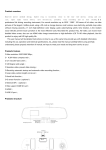
IMPOSA MONITOR SOFTWARE
User’s Manual
Version Number: 1.0
IMPOSA MONITOR
Copyright Statement
All rights reserved. Unless authorized by written permission from the
owner of IMPOSA™, copy of any part of this manual by any means including, but
not limited to, telecommunication, handwriting, photo-copying, CD-burning by
any person or organization is strictly prohibited.
IMPOSA™ reserves the rights to do any change or modification to this
manual without prior notice to any person or organization. No licensing or
royalty or whatsoever is required or involved with regard to technology in this
manual.
1
IMPOSA MONITOR
Version Log
Version
Date of Modif.
Description
Modified by
No.
1.0
2007-10-26
First version
Lin Zhenyu
2
IMPOSA MONITOR
Table of content
1.
. Introduction ........................................................................................................................... 1
1.1 Software Introduction.......................................................................................................... 1
1.2 General ............................................................................................................................. 1
2.
.System Platform and Installation....................................................................................... 2
2.1 System platform .................................................................................................................. 2
2.2 Connection Device .............................................................................................................. 2
2.3 Installation and Start up....................................................................................................... 3
3.
.Software Interface and Operations ................................................................................... 3
3.1 Imposa Monitor Interface .................................................................................................... 3
3.2 Imposa Monitor Bar Operation ........................................................................................... 5
3.3 Imposa Monitor Exit and Other Operations ...................................................................... 13
3
IMPOSA MONITOR
1.
. Introduction
1.1 Software Introduction
IMPOSA MONITOR is a software for pixel diagnosis. Characterized by high accuracy
of detecting, vivid interfaces of operation, IMPOSA MONITOR is easy to manage. The
following are general functions:
1. It can detect if there are defective pixels in LED display, can tell their colors and
positions in each of the cabinets, and so on.
2. We can detect by manual operation the working status of each pixel in current LED
display any time, and we can also set time to do pixel diagnosis on the screen
automatically
3. We can check any time or save the result of detecting. A report can be generated
by the software. The report can even be sent to a designated mailbox automatically.
1.2 General
IMPOSA MONITOR is composed of four parts, including Main Menu, Status, Set Bar,
and Last Detect Time. Of the four parts, Set Bar consists of six parts; they are
Configuration, Communication, Scan & Detect, Schedule, E-Mail Setting, and Log. The
whole interface is shown in Fig 1.1. If arrows in
means enter into next operation,
are colored, the
means back to the last operations.
or
shows whether the current system is
detailed functions will be introduced in the following sections.
1
. The
IMPOSA MONITOR
FIG 1.1 IMPOSA MONITOR interface
2.
.System Platform and Installation
2.1 System
platform
Intel Pentium or Celeron MAX533 MHz central processor unit or compatible
system and up
RAM: 128 MB or more
With USB port or parallel RS232 port
10/100 M Ethernet
CD-ROM Driver
Windows 2000,XP or Windows 2003
Display Mode: 1024×768, 16 bit true color
2.2 Connection
Device
LDU, IMPOSA™, cabinet photo sensor
The system must be connected with at least one IMPOSA™. If not, some functions of
this software will not work
2
IMPOSA MONITOR
2.3 Installation and Start up
Startup, double click icon
, or click IMPOSA MONITOR in \Program Files\Led
control\IMPOSA MONITOR to start the software.
3.
.Software Interface and Operations
3.1 Imposa Monitor Interface
Once started up, the IMPOSA MONITOR will display an interface such as shown in FIG
3.1.
FIG 3.1 IMPOSA MONITOR Interface
3.1.1 Main Menu-Back and Next
if arrow is colored, click
while clicking
means getting back to the last step.
3
and enter into next step,
IMPOSA MONITOR
3.1.2 Status Bar
(1)
This status in the system is default status. If
detecting LED screen, there is not defective pixel in LED screen.
(2)
is shown after
The system will return to this status after detecting of the LED screen
is done, which means there are defective pixels in LED screen.
(3)
This status shows communication error. The user should check the
connection between LDU and PC, and connection between main board and the screen.
3.1.3 Prompt Bar
shows the time when user detected the screen last.
3.1.4 Set Bar
Six parts are included in this bar. They are Configuration(set up the system),
Communication(detection of communication), Scan & Detect(detection of defective pixel),
Schedule(auto detecting at preset time), E-Mail Setting(to set parameters of mailbox),
4
IMPOSA MONITOR
Log(Save detection results)
3.2 Imposa Monitor Bar Operation
3.2.1 Configuration
Click Configuration in
, an interface as shown in FIG 3.2 will
pop up . We can set password of the software and choose between showing the state of
defective pixels detected and not showing them in Status Bar. If any of the configuration is
to be applied, please tick
. After ticking
in
, and click
in
, or click
, it will pop out an interface as in FIG 3.3 .
, and you
Input a password of not more than 10 characters twice, click
will succeed in setting the password. Click
the main interface
or
to go back to
FIG 3.2 Configuration Interface
FIG 3.3 Password Setting Interface
3.2.2 Communication
Click Communication in
, it will pop out an interface
as shown in FIG 3.4. With this interface we can set the parameters of communication
between computer and LED screen. If parameters were incorrect, it will show
5
IMPOSA MONITOR
after clicking
. Then you it can not perform
defective pixel diagnosis in LED screen. If parameters are set correctly, it will show
success after clicking
. This means you can detect now. Click
or
to go back to main interface
Specific Parameters as following:
1.
2.
Select Ethernet or RS232/485
3.
Choices between COMs and Baud Rates
4.
Choices of LDU Address
6
IMPOSA MONITOR
FIG 3.4 Communication Parameters Setting Interface
3.2.3 Scan & Detect
Click Scan & Detect in
and you will see Fig
3.5a and 3.5b. Through this configuration, we can carry out the defective pixel detection.
7
IMPOSA MONITOR
FIG 3.5 a. Defective Pixel Detection Interface (There is defective pixel in the cabinet)
FIG 3.5 b. Defective Pixel Detection Interface (There is no defective pixel in the
cabinet)
Click
in FIG 3.5 to start the defective pixel detection function.
shows the detecting in progress. Click
to get
the exact address of the defective pixel in each cabinet. As FIG 3.6 shows, click
or
to return to the main interface.
8
IMPOSA MONITOR
FIG 3.6 The exact address of the defective pixel
From FIG 3.6 you can observe the exact address of the tile with defective pixel as well as
the color of the defective pixel and its coordinates in the tile.
means the red pixel is broken. The same is true with others. Press
to recheck the pixels. Press
to make the pop up
of a .TXT file, see FIG 3.7, it includes the information such as cabinet address and type,
number of defective pixel, color of defection and their coordinates and so on. Click
to return to the defective pixel detecting interface. See FIG 3.5b.
9
IMPOSA MONITOR
FIG 3.7 PixelsCheck.TXT Notepad
3.2.4 Schedule
Click Schedule in
to make the appearance of FIG 3.8.
FIG 3.8 Auto Detecting Schedule Interface
The detecting frequency and time of the display can be set up. After detecting, the
final result will be sent out to a designated mailbox. There are three conditions:
10
IMPOSA MONITOR
(1)
Diagnose at a certain time in a certain day.
(2)
Diagnose at a certain time in a certain day of each week.
(3)
Diagnose at a certain time in a certain day of each month.
to begin the apply function. Click
After setting, click
or
to return to the main interface.
3.2.5 E-Mail Setting
and you will see FIG 3.9. The
Press E-Mail Setting in
defective pixel found out will be sent to the designated mailbox.
11
IMPOSA MONITOR
[email protected]
FIG 3.9 E-Mail Setting Dialogue Box
The dialogue box includes:
(1) User’s email address.
(2) Sender’s
name,
email
address,
SMTP
and
password.
[email protected]
(3) The subject and content.
;
After setting, click
or
to begin the apply function. Click
to return to the main interface.
3.2.6 Log
12
IMPOSA MONITOR
Press Log in
and there will appear an interface like FIG 3.10. Click
in
.U
sers need to save the detecting report in the LOG address directory of installing directory.
FIG 3.10 Detecting Log Dialogue Box
In FIG 3.10, click
to clear the Log files. After setting the saving
to begin the apply function. Click
address of the log files, click
or
to return to the main interface.
3.3 Imposa Monitor Exit and Other Operations
You can’t exit the IMPOSA MONITOR software just by clicking the button
in the
dialogue box. The correct way is to click the symbol, with the right key of the mouse,
on
13
IMPOSA MONITOR
which is at the right corner of the computer, and a menu
will pop up. Click the shut down and a password verification
like
dialogue box will shop up. Input your password and press
to exit from
the software.
FIG 3.11 Password Verification Dialogue Box
there will pop up a password
Click Imposa Console in
verification dialogue window just as FIG 3.11. Input the password and press
to login onto the main control interface. See FIG 3.12.
14
IMPOSA MONITOR
Main Control Interface
to enter the pixel detecting window. As
Click Manual Detect in
FIG 3.13 shows. The operation for the window has been explained before.
15
IMPOSA MONITOR
FIG 3.13 Pixel diagnosis window
That is all for the basic introduction to the IMPOSA MONITOR software. Now you can
enjoy the function of getting to know which pixel is working fine or not.
16