1
Pico DeviceNet
Communication
Interface
1760-DNET
User Manual
Important User Information
Solid state equipment has operational characteristics differing from those of
electromechanical equipment. Safety Guidelines for the Application,
Installation and Maintenance of Solid State Controls (publication SGI-1.1
available from your local Rockwell Automation sales office or online at
http://www.rockwellautomation.com/literature) describes some important
differences between solid state equipment and hard-wired electromechanical
devices. Because of this difference, and also because of the wide variety of
uses for solid state equipment, all persons responsible for applying this
equipment must satisfy themselves that each intended application of this
equipment is acceptable.
In no event will Rockwell Automation, Inc. be responsible or liable for
indirect or consequential damages resulting from the use or application of
this equipment.
The examples and diagrams in this manual are included solely for illustrative
purposes. Because of the many variables and requirements associated with
any particular installation, Rockwell Automation, Inc. cannot assume
responsibility or liability for actual use based on the examples and diagrams.
No patent liability is assumed by Rockwell Automation, Inc. with respect to
use of information, circuits, equipment, or software described in this manual.
Reproduction of the contents of this manual, in whole or in part, without
written permission of Rockwell Automation, Inc. is prohibited.
Throughout this manual, when necessary we use notes to make you aware of
safety considerations.
WARNING
IMPORTANT
ATTENTION
Identifies information about practices or circumstances
that can cause an explosion in a hazardous environment,
which may lead to personal injury or death, property
damage, or economic loss.
Identifies information that is critical for successful
application and understanding of the product.
Identifies information about practices or circumstances
that can lead to personal injury or death, property
damage, or economic loss. Attentions help you:
• identify a hazard
• avoid a hazard
• recognize the consequence
SHOCK HAZARD
Labels may be located on or inside the equipment (e.g.,
drive or motor) to alert people that dangerous voltage may
be present.
BURN HAZARD
Labels may be located on or inside the equipment (e.g.,
drive or motor) to alert people that surfaces may be
dangerous temperatures.
Table of Contents
Preface
Who Should Use this Manual. . . . . . . . . . .
Purpose of this Manual . . . . . . . . . . . . . . .
Common Techniques Used in this Manual .
Rockwell Automation Support . . . . . . . . . .
.
.
.
.
.
.
.
.
.
.
.
.
.
.
.
.
.
.
.
.
.
.
.
.
.
.
.
.
.
.
.
.
.
.
.
.
.
.
.
.
.
.
.
.
.
.
.
.
P-1
P-1
P-2
P-3
System Overview . . . . . . . . . . . . . . . . . . . . . .
Structure of the Unit . . . . . . . . . . . . . . . . . . . .
Communication Profile . . . . . . . . . . . . . . . . . .
Hardware and Operating System Requirements
Use Other Than Intended . . . . . . . . . . . . . . . .
.
.
.
.
.
.
.
.
.
.
.
.
.
.
.
.
.
.
.
.
.
.
.
.
.
.
.
.
.
.
.
.
.
.
.
.
.
.
.
.
.
.
.
.
.
1-1
1-2
1-2
1-2
1-3
Connect to the Basic Unit . . . . . . . . . . . . . . . . . . . . . . .
Connect the Power Supply . . . . . . . . . . . . . . . . . . . . . .
Connect DeviceNet . . . . . . . . . . . . . . . . . . . . . . . . . . . .
EMC Compatible Wiring . . . . . . . . . . . . . . . . . . . . . . . .
Potential Isolation . . . . . . . . . . . . . . . . . . . . . . . . . . . . .
Data Transfer Rates – Automatic Baud Rate Recognition .
.
.
.
.
.
.
.
.
.
.
.
.
2-1
2-2
2-2
2-3
2-4
2-4
.
.
.
.
.
.
.
.
.
.
3-1
3-1
3-5
3-6
3-6
Chapter 1
Pico DeviceNet Interface
Chapter 2
Installation
Chapter 3
Operate the DeviceNet Interface
Initial Power On . . . . . . . . . . . . . . .
DeviceNet Setting the Slave Address
LED Status Displays. . . . . . . . . . . . .
Cycle Time of the Pico Basic Unit. .
EDS File . . . . . . . . . . . . . . . . . . . . .
.
.
.
.
.
.
.
.
.
.
.
.
.
.
.
.
.
.
.
.
.
.
.
.
.
.
.
.
.
.
.
.
.
.
.
.
.
.
.
.
.
.
.
.
.
.
.
.
.
.
.
.
.
.
.
.
.
.
.
.
.
.
.
.
.
.
.
.
.
.
.
.
.
.
.
Chapter 4
DeviceNet Functions
Object Model . . . . . . . . . . . . . . . . . . . . . . . . . . . . . . . . . . 4-1
DeviceNet Communication Profile . . . . . . . . . . . . . . . . . . . 4-9
Chapter 5
Direct Data Exchange with
Pico/GFX (Polled I/O Connection)
Input data: Mode, S1 – S8 . . . . . . . . . . . . . . . . . . . . . . . . . 5-2
Output Data: Mode, R1 – R16 . . . . . . . . . . . . . . . . . . . . . . 5-4
Chapter 6
Application Examples for Pico
Read/Write Date and Time . . . . . .
Read/Write Image Data . . . . . . . . .
Read/write function block data . . .
Analysis – error codes via PicoLink
.
.
.
.
.
.
.
.
.
.
.
.
.
.
.
.
.
.
.
.
.
.
.
.
.
.
.
.
.
.
.
.
.
.
.
.
.
.
.
.
.
.
.
.
.
.
.
.
.
.
.
.
.
.
.
.
.
.
.
.
.
.
.
.
.
.
.
.
.
.
.
.
6-2
6-4
6-20
6-34
Chapter 7
Pico GFX Control Commands
1
Version history . . . . . . . . . . . . . . . . . . . . . . . . . . . . . . . . . 7-2
Read/write date and time . . . . . . . . . . . . . . . . . . . . . . . . . 7-2
Read/write image data. . . . . . . . . . . . . . . . . . . . . . . . . . . . 7-7
Publication 1760-UM003A-EN-P - September 2005
Table of Contents
2
Read/write function block data . . . . . . . . . . . . . . . . . . . . . 7-20
Analysis – error codes via PicoLink . . . . . . . . . . . . . . . . . . 7-64
Chapter 8
Troubleshoot Your Controller
Chapter A
Specifications
Technical Data . . . . . . . . . . . . . . . . . . . . . . . . . . . . . . . . . A-1
Dimensions. . . . . . . . . . . . . . . . . . . . . . . . . . . . . . . . . . . . A-4
Glossary
Index
Publication 1760-UM003A-EN-P - September 2005
Preface
Read this preface to familiarize yourself with the rest of the manual. It
provides information concerning:
•
•
•
•
•
Who Should Use this
Manual
who should use this manual
the purpose of this manual
related documentation
conventions used in this manual
Rockwell Automation support
Use this manual if you are responsible for designing, installing,
programming, or troubleshooting control systems that use Pico
controllers.
You should have a basic understanding of electrical circuitry and
familiarity with relay logic. If you do not, obtain the proper training
before using this product.
Purpose of this Manual
This manual is a reference guide for Pico controllers and the Pico
DeviceNet Interface. It describes the procedures you use to install,
wire, and troubleshoot the Pico DeviceNet Interface.
Refer to publication 1760-GR001, Pico Controller Getting Results
Manual for a basic overview of Pico and an introduction to Pico
programming.
1
Publication 1760-UM003A-EN-P - September 2005
Preface
2
Related Documentation
The following documents contain additional information concerning
Rockwell Automation products. To obtain a copy, contact your local
Rockwell Automation office or distributor.
For
Read this Document
Document Number
A basic overview of Pico and an introduction to Pico programming.
Pico Controller Getting Results
Manual
1760-GR001
In-depth information on grounding and wiring Allen-Bradley
programmable controllers
Allen-Bradley Programmable
Controller Grounding and Wiring
Guidelines
1770-4.1
A description of important differences between solid-state
programmable controller products and hard-wired electromechanical
devices
Application Considerations for
Solid-State Controls
SGI-1.1
An article on wire sizes and types for grounding electrical equipment
National Electrical Code - Published by the National Fire
Protection Association of Boston, MA.
A complete listing of current documentation, including ordering
instructions. Also indicates whether the documents are available on
CD-ROM or in multi-languages.
Allen-Bradley Publication Index
SD499
A glossary of industrial automation terms and abbreviations
Allen-Bradley Industrial Automation
Glossary
AG-7.1
Common Techniques Used
in this Manual
Publication 1760-UM003A-EN-P - September 2005
The following conventions are used throughout this manual:
• Bulleted lists such as this one provide information, not
procedural steps.
• Numbered lists provide sequential steps or hierarchical
information.
Preface
Rockwell Automation
Support
3
Rockwell Automation offers support services worldwide, with over 75
Sales/Support Offices, 512 authorized Distributors and 260 authorized
Systems Integrators located throughout the United States alone, plus
Rockwell Automation representatives in every major country in the
world.
Local Product Support
Contact your local Rockwell Automation representative for:
•
•
•
•
sales and order support
product technical training
warranty support
support service agreements
Technical Product Assistance
If you need to contact Rockwell Automation for technical assistance,
please review the Troubleshooting section on page 8-1 in this manual
first. Then call your local Rockwell Automation representative.
You can also find a local Rockwell Automation Technical Support
contact at:
• http://support.automation.rockwell.com/contactinformation/
Your Questions or Comments on this Manual
If you find a problem with this manual, or you have any suggestions
for how this manual could be made more useful to you, please
contact us at the address below:
Rockwell Automation
Control and Information Group
Technical Communication, Dept. A602V
P.O. Box 2086
Milwaukee, WI 53201-2086
or visit our internet page at:
http://www.ab.com/pico or http://www.rockwellautomation.com
Publication 1760-UM003A-EN-P - September 2005
Preface
4
Publication 1760-UM003A-EN-P - September 2005
Chapter
1
Pico DeviceNet Interface
The 1760-DNET communication module has been developed for
automation tasks with the DeviceNet field bus. The 1760-DNET acts as
a ’gateway’ and can only be operated in conjunction with Pico and
Pico GFX-70 controllers.
The system unit consists of the Pico control device and the
1760-DNET DeviceNet gateway and operates exclusively as a slave
station on the DeviceNet fieldbus system.
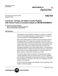
System Overview
The DeviceNet slaves are integrated into a DeviceNet fieldbus system.
Figure 1.1 Implementation of 1760-DNET in DeviceNet
a
b
a Master area, SLC 500 programmable controller or PC with CAN card
b Slave area, e.g.: Pico or Pico GFX-70 with DeviceNet interface
1
Publication 1760-UM003A-EN-P - September 2005
1-2
Pico DeviceNet Interface
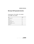
Structure of the Unit
Figure 1.2
a
MS
f
e
b
1
Pico-Link Socket
2
5-pin DeviceNet Connector
3
24V dc Power Supply
4
Equipment Rating Plate
5
Network Status LED
6
Module Status LED
NS
d c
Communication Profile
Hardware and Operating
System Requirements
Publication 1760-UM003A-EN-P - September 2005
• Predefined master/slave communication settings
– The I/O polling connection is used for the transfer of 3 bytes
of input data (R1 to R16) and 3 bytes of output data (S1 to S8)
between the base unit with gateway interconnection and the
DeviceNet programmable controller.
– The I/O Change of State/Cyclic connection (acknowledged,
unacknowledged) is used to transfer 2 bytes of diagnostic
data from the control relay to the DeviceNet programmable
controller.
– The explicit connection set-up is used for read/write access
to function relay parameters in the control relay. This type of
connection set-up also supports the configuration, diagnostics
and management services of the control relay.
• DeviceNet Communication adapter profile (device type 12),
which has been expanded by requests
• Group 2 server
• UCMM-capable device
• Dynamic set-up of explicit and I/O connections are possible
• Device Heartbeat Message
• Device Shutdown Message
• Offline communication settings
The 1760-DNET expansion unit operates together with Pico Series B
and Pico GFX-70 controllers.
Pico DeviceNet Interface
Use Other Than Intended
1-3
Pico and Pico GFX-70 controllers may not be used to replace
safety-relevant control circuits, e.g.:
•
•
•
•
Furnace,
emergency-stop,
crane or
Two-hand safety controls.
Publication 1760-UM003A-EN-P - September 2005
1-4
Pico DeviceNet Interface
Publication 1760-UM003A-EN-P - September 2005
Chapter
2
Installation
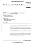
Mounting is the same as for Pico Expansion I/O modules.
Connect to the Basic Unit
1
2
4
3
connector
Pico
Pico GFX-70
1760-DNET
1
Publication 1760-UM003A-EN-P - September 2005
2-2
Installation
Connect the Power Supply
The module operates with a 24V dc supply voltage (see Power Supply
specifications on page A-3).
Always ensure safe electrical isolation between the
extra low voltage (SELV) and the 24V power supply.
WARNING
+24 V
0V
>1A
+24 V 0 V
Connect DeviceNet
A 5-pin DeviceNet plug connects the DeviceNet interface of the
device to the DeviceNet field bus.
Use a special DeviceNet plug and DeviceNet cable for this connection.
Both are specified in the ODVA specification. The type of cable
determines the maximum available cable length and the data transfer
rate.
DeviceNet Pin Assignment
1
1
V– GND (Black)
2
2
CAN_L (Blue)
3
3
Shield (Clear)
4
CAN_H (White)
5
V+ (24 V) (Red)
4
5
Publication 1760-UM003A-EN-P - September 2005
Installation
2-3
All pins of the plug must be connected to ensure safe communication
of the 1760-DNET on the fieldbus DeviceNet. This also applies to the
24V bus voltage.
The gateway does not participate in communication
on the bus if the bus voltage is not available. The
Network status LED is OFF in this situation.
IMPORTANT
Terminating Resistors
The first and last node of a DeviceNet network must be terminated by
means of a 120 O bus termination resistor. This device is
interconnected between the CAN_H and CAN_L terminals.
0
RT
EMC Compatible Wiring
1
. . .
n
RT
Electromagnetic interference may lead to unwanted effects on the
communications fieldbus, which can be significantly reduced by using
the cable described above, a shielded RJ45 connector and by
terminating the screen.
The two figures below show the correct termination of the shielding.
Figure 1.3 Shield Connection to the Mounting Rail
Publication 1760-UM003A-EN-P - September 2005
2-4
Installation
Figure 1.4 Shield Connection to the Mounting Plate
Potential Isolation
The following potential isolation specifications apply to 1760-DNET
interfaces:
a
b
+ –
c
Data Transfer Rates –
Automatic Baud Rate
Recognition
1
Safe electrical isolation between PicoLink and the 240 VAC mains
2
Simple electrical isolation to the DeviceNet communication bus
3
Power supply 24 V DC
After it is switched on, the 1760-DNET module automatically detects
the data transfer rate of the communication network. However, this is
possible only if at least one network node transmits valid message
frames. The device supports the following data transfer rates
according to ODVA:
• 125 kbps,
• 250 kbps,
• 500 kbps,
Maximum Distances and Bus Cable Lengths
The max. bus length is not determined by the data transfer rate, but
rather by the cable used. The following cables are permitted:
• Thin Cable,
• Thick Cable
Publication 1760-UM003A-EN-P - September 2005
Installation
2-5
• or Flat Cable.
The data cable requirements are specified by the ODVA.
Baud Rate (kbps)
Maximum Cable Length (m)
Thick Cable
Thin Cable
Flat Cable
125
500
100
420
250
250
100
200
500
100
100
100
Publication 1760-UM003A-EN-P - September 2005
2-6
Installation
Publication 1760-UM003A-EN-P - September 2005
Chapter
3
Operate the DeviceNet Interface
Initial Power On
Before you apply power to the DeviceNet Interface, verify that it is
properly connected to the power supply, to the bus connectors and to
the basic unit. Then, switch on the power supply for the basic unit
and the DeviceNet Interface.
The LEDs of the 1760-DNET flicker.The device automatically detects
the correct baud rate (see Data Transfer Rates – Automatic Baud Rate
Recognition on page 2-4). The GW information (intelligent station
connected) is displayed on the basic unit.
When the device in the network management is switched to the
‘Operational’ status, the state of the GW changes to static even on the
devices with a flashing GW,(see Network Status LED (NS) on
page 3-5).
If the unit has default configuration (node ID = 127), you need to
define the DeviceNet slave address.
DeviceNet Setting the
Slave Address
Each DeviceNet slave requires a unique address (MAC ID) in the
DeviceNet structure. Within a DeviceNet structure, you can assign a
maximum of 64 addresses (0 to 63). Each MAC ID must be unique
within the entire bus structure.
There are three ways to set the DeviceNet address of an 1760-DNET:
•
•
•
•
Using the integrated display and keyboard on the basic unit
Using Pico-Soft V3.01 or higher on the PC
Using Pico-Soft Pro on the PC
Using the configuration software of the installed master
programmable controller (possibly by means of an explicit
message).
Set the Address on the Controller Unit with Display:
Make sure that:
• The respective basic units and DeviceNet Interface are supplied
with voltage.
1
Publication 1760-UM003A-EN-P - September 2005
3-2
Operate the DeviceNet Interface
• The basic unit is accessible (password protection not activated).
• The basic unit has a valid operating system version.
• The basic unit is in STOP mode.
+
1. Press the DEL + ALT keys to change to the special menu.
PASSWORD...
SYSTEM...
GB D F E I
CONFIGURATOR
PASSWORD...
2. Use the cursor keys
Í
or
Ú
to change to the Configurator.
SYSTEM...
GB D F E I
CONFIGURATOR
3. Press OK.
NET...
4. Select the LINK.... menu with the Pico-GFX units.
LINK...
5. Press OK.
The DEVICENET menu appears.
DEVICENET
MAC ID 0026
222-01.20- D
6. Set the address using the cursor keys:
– Set the current numeric value using the Í or Ú keys.
– You can change the current numeric value using ú or í.
2
1
o
.
.
.
.
.
.
9
0
0 0 0 P
1
P 0 0 0
1
o
1
2
Publication 1760-UM003A-EN-P - September 2005
0
.
9 .
. .
.
.
Operate the DeviceNet Interface
3-3
7. Press OK to accept the address.
8. Press ESC to cancel address input.
Information about the 4th display line:
xxx - xx . xx - xx
222 - 02. 10 - B
Hardware version, Index: b
Software version, OS version: 2.1
Device identity: 1760-DNET
Set the Address with Pico-SOFT
With Pico-SOFT, version 3.1
‹Menu l Online l Configuration of expansion units›
With Pico-SOFT, version 4.01 and later
‹Menu l Communication l Configuration l Expansion units l
1760-DNET›.
IMPORTANT
IMPORTANT
The menu is only available in the communication
view; therefore please activate the ‘Communication’
tab.
After you have modified the MAC ID via the basic
unit, restart the DeviceNet Interface by switching
power off and on.
Set the Address with the DeviceNet Master
The configuration software supplied with your master programmable
controller offers the option of setting or modifying the MAC ID of the
gateway.
Publication 1760-UM003A-EN-P - September 2005
3-4
Operate the DeviceNet Interface
For more information, refer to the programmable controller’s
documentation.
You can also use various other software packages to modify the MAC
ID by sending an explicit message. Do so by using the corresponding
service of the DeviceNet object (see DeviceNet Object on page 4-6).
LED Status Displays
The DeviceNet Interface expansion module is equipped with two
indicator LEDs for quick diagnostics. The module monitors itself as
well as the DeviceNet communication bus.
Module Status LED (MS)
The dual-color LED (GREEN/RED) indicates the status of the module.
It monitors whether the device is fully functional and operates without
fault.
Table 3.1 Module Status LED Description
LED Status
Description
Off
No power supply at the module.
Green
The module is in normal operational
state.
t
Green flashing
The module is in standby mode. The
configuration is faulty or incomplete,
or a configuration does not exist.
t
Red flashing
An error has occurred. There is no
need to replace the module.
Red
A fatal error has occurred. The
module must be replaced.
Green-Red flashing
The module is performing a self-test.
t
t
t
t
Publication 1760-UM003A-EN-P - September 2005
Operate the DeviceNet Interface
3-5
Network Status LED (NS)
The dual-color LED (GREEN/RED) indicates the status of the
DeviceNet communication bus. This function monitors operability and
correct operation of the module.
Table 3.2 Network Status LED Description
Cycle Time of the Pico
Basic Unit
LED Status
Description
OFF
The module is offline. Either it is performing
a DUP_MAC_ID test or power is missing at
the device or bus.
t
GREEN
flashing
The module is online. Communication has
not yet been established.
t
GREEN
The module is online and the connection is
active.
t
RED
flashing
Time-out of at least one I/O connection
(time-out state).
RED
A fatal network error has occurred. The
module has shut down communication.
GREEN-RED
flashing
The module has detected a network access
error and is now in communication error
state.
t
t
t
Network traffic between the Pico basic unit and the DeviceNet
Interface via Pico-LINK extends the cycle scan time of the basic unit
In the worst case, this time can be extended by 25 ms.
Please take this factor into account when you calculate the response
times of the basic unit.
EDS File
You can implement the module into the DeviceNet structure by means
of a standardised EDS file (Electronic Data Sheet).
This EDS file primarily defines the polled I/O connection, the COS I/O
connection and the cyclic I/O connection of the gateway. It does not
contain data or parameters (Pico object) for functions of the controller.
These functions are accessed by means of explicit messages.
You can download updates of the EDS file from:
http://www.ab.com/networks/eds/
Publication 1760-UM003A-EN-P - September 2005
3-6
Operate the DeviceNet Interface
Search for the catalog number 1760.
IMPORTANT
Publication 1760-UM003A-EN-P - September 2005
The Identity Object entry - Major Revision defines
the current operating system state of the 1760-DNET
communication module. As the device with a newer
operating system version can deviate from the EDS
description in this point, this entry must be modified
accordingly, Identity Object on 4-4.
Chapter
4
DeviceNet Functions
Object Model
The Pico DeviceNet Interface is based on the Communications
Adapter Profile according to the ODVA specifications (Release V2.0).
The DeviceNet object model can be used to describe all 1760-DNET
functions. The object model reflects the principle of communication at
the application layer. This manual deals in the following only with
objects relevant for your application. Primary topic is the
manufacturer-specific class Pico object.
Figure 3.5 DeviceNet Objects
Pico-LINK
Protocol Handler
Pico
Object
Identity
Object
Assembly
Object
Object
Acknowledge Handler
Object
Message Router
Object
COS/Cyclic I/O
Connection
Explicit Message
Connection
Bit Strobed I/O
Connection
Polled I/O
Connection
DeviceNet
Object
Dynamic
Connection
Connection Object
DeviceNet
The DeviceNet objects in the illustration can be compiled again as
‘Management objects’, ‘Connection objects’ and ‘Manufacturer-specific
objects’.
1
Publication 1760-UM003A-EN-P - September 2005
4-2
DeviceNet Functions
Table 3.3
Objects
Object Address
Class ID (Hex)
Instance ID (Hex)
Identity Object
01
01
Message Router
02
01
DeviceNet Object
03
01
Connection
Object
05
01 ... 04,
04 ... 0F
64
01
Service Address
Function
(Hex)
Attribute ID (Hex)
Management Objects
Connection Objects
Manufacturer-Specific
Objects
Pico Object
Direct Access:
inputs/outputs,
mode
Read
0E
Write
10
Extended access:
time, image data,
function blocks
32
Pico Series B
Pico GFX-70
Assembly Object
04
64 ... 66
Management Objects
These objects define DeviceNet-specific data and functions and must
be supported by all DeviceNet devices:
• Identity Object
The Identity Object (Class ID 01hex) contains all data for unique
identification of a network node, e.g. the Vendor ID, Device
Type and Product Code. It also comprises the actual status of a
device, the serial number and the product name.
Detailed information can be found on page 4-4.
Publication 1760-UM003A-EN-P - September 2005
DeviceNet Functions
4-3
• Message Router Object
The Message Router Object (Class ID 02hex) provides access to
all classes and instances in the device by means of explicit
messages.
Connection Objects
These objects define messages exchanged via DeviceNet:
• DeviceNet Object
All devices must support the DeviceNet object (Class ID: 03hex).
It defines the physical interconnection of a device to the
DeviceNet network, meaning it also contains the device address
(MAC ID) and the currently set transmission speed, for example.
Detailed information page 4-6.
• Connection Object
The Connection Object (Class ID: 05hex) is supported by all
DeviceNet devices in at least one instance. It defines the access
to data via I/O messages or explicit messages, the path and
length of producer/consumer data, the CAN connection
identifier, the watchdog and the error response.
Publication 1760-UM003A-EN-P - September 2005
4-4
DeviceNet Functions
Manufacturer-Specific Objects
These objects define device-specific data and functions (Application
Objects, Parameter Object, Assembly Object).
• Application Objects – Pico Object
Application objects (Class ID: 64hex) describe simple
applications for automation engineering. They are either
predefined in the DeviceNet object library or by the user.
Refer to Pico Object on page 4-6.
• Assembly Objects
The Assembly Object (Class ID: 04hex) provides the user with
mapping options, that is attribute data of different instances in
different classes can be grouped together to form a single
attribute of an instance in an assembly object.
Identity Object
Object Address
Function
Access
Class ID
Instance ID
Attribute ID
Service Code
01hex
01hex
Table 4.4
Table 4.5
Table 4.4 Attribute IDs of the Identity Object Instance
Publication 1760-UM003A-EN-P - September 2005
Attribute Access Name
ID
Description
Size
(byte)
1
Read
Vendor ID
Allen-Bradley Vendor ID = 1
2
2
Read
Device type
The 1760-DNET belongs to the
communication adapters category. Its
value is 12dec.
2
3
Read
Product code
Allen-Bradley product code = 18410
2
DeviceNet Functions
4-5
Table 4.4 Attribute IDs of the Identity Object Instance
Attribute Access Name
ID
Description
4
Device
version
Two bytes are returned when reading the
device version.
Hardware
version,
The low byte defines the hardware
version, the high byte the operating
system version.
1
Read
Operating
system
version
Size
(byte)
1
5
Read
Status
This attribute describes the global status
of the device.
2
6
Read
Serial
number
The serial number of the device can be
read with this attribute.
4
7
Read
Product name The product name 1760-DNET is stored as 12
hex value in ASCII format.
9
Read
Configuration This attribute returns a counter value that
consistency
monitors the number of modifications in
value
non-volatile memory (E2PROM).
2
10
Read/
Write
Heartbeat
Interval
2
Defines an interval between heartbeat
messages in [s].
Service Code
The Identity Object Instance and also the following instances support
the services listed in the table below.
Table 4.5 Service Code
Service Code Value
Service Name
Description
05hex
Reset
Calls the reset function of
the communication module.
0Ehex
Get_Attribute_Single
This service can be used to
fetch the value of a selected
attribute from the
communication module.
10hex
Set_Attribute_Single
This service can be used to
set a selected attribute in
the device.
Publication 1760-UM003A-EN-P - September 2005
4-6
DeviceNet Functions
DeviceNet Object
Object Address
Function
Access
Class ID
Instance ID
Attribute ID
Service Code
03hex
01hex
Table 4.6
Table 4.5
The DeviceNet object instance is used to configure the
communication module and to define the physical environment. The
Service Codes used for the Identity Object also apply in this case.
Table 4.6 DeviceNet Object Instance Attribute IDs
Attribute Access Name
ID
Description
Size
(byte)
1
Read/
Write
MAC ID
The MAC ID represents the network
address of a network node. It can be read
and set for the module via the DeviceNet
fieldbus by means of this attribute. Range
of values: 0 to 63dec. (see DeviceNet
Setting the Slave Address on page 3-1)
1
2
Read/
Write
Baud rate
This attribute can be used to read/set the
data transfer rate for communication
functions. Range of values: 0 to 2, 125 to
500 kbps (see Data Transfer Rates –
Automatic Baud Rate Recognition on page
2-4).
1
3
Read/
Write
BOI (Bus-Off
interrupt)
This attribute can be used to define the
1
reaction to a Bus-Off event (CAN-specific).
4
Read/
Write
Bus-Off
counter
This values shows how often a Bus-Off
event has occurred. Range of values: 0 to
255.
1
Pico Object
Object Address
Function
Access
Class ID
Instance ID
Attribute ID
Service Code
64hex
01hex
Table 4.7
Table 4.8
The Pico object can be used to access Pico/GFX functions via the
DeviceNet communication bus . The table below shows the attributes
Publication 1760-UM003A-EN-P - September 2005
DeviceNet Functions
4-7
supported by this object. The two bytes of attributes 1 and 2 provide
the diagnostic data of the device. You can use attribute 3 to access the
outputs (S1 to S8) and attribute 4 to access the inputs (R1 of R16) of
the basic unit.
By using a DeviceNet configuration software (e.g. RSNetworx), you
can map these data directly to the corresponding memory areas of a
programmable controller.
Table 4.7
Attribute Access Name
ID
Description
Size
(byte)
1
Read
Pico Status
This attribute can be used to read the
status of Pico (RUN or STOP). See
Table 4.9.
1
2
Read
Coupling
This attribute can be used to read the
status of Pico-LINK. See Table 4.9.
1
Module
Status
3
Read
Pico transfers the input data to the
DeviceNet bus. The Pico outputs S1 to S8
must be used for this function. The
structure of these 3 bytes is described in
detail under Input data: Mode, S1 – S8 on
page 5-2, .
3
4
Read/W Outputs –
The DeviceNet bus transfers the data to
rite
Receive Data Pico. The Pico inputs R1 to R16 must be
used for this function. The structure of
these 3 bytes is described in detail under
Output Data: Mode, R1 – R16 on page 5-4,
.
3
5
Read/W Predefined
rite
Outputs
3
Inputs –
Send Data
This attribute can be used to preset the
output data ("R" data) at the
1760-DNETduring start-up. The structure
of these 3 bytes is described in detail
under Output Data: Mode, R1 – R16 on
page 5-4.
Service Code
The Pico object instance supports the following services.
Publication 1760-UM003A-EN-P - September 2005
4-8
DeviceNet Functions
Table 4.8 Service Code
Service Code Value
Service Name
Description
0Ehex
Get_Attribute_Single
This service can be used to
fetch the value of a selected
attribute from the
communication module.
10hex
Set_Attribute_Single
This service can be used to
set a selected attribute in
the device.
32hex
Extended access(1)
This service can be used to
address the supplementary
parameters(1) of the control
relay:
(1) Additional parameters are “Time”, “Image data” and “Function block”. Addressing of the parameters is Pico
specific and is described in chapters 5 – 7 in detail.
Extended access is implemented via explicit message transfer. This transfer protocol allows the exchange of
control data. Further information about the transfer protocol can be found in section “DeviceNet
Communication profile” on page 9.
Change of State I/O Connection
Table 4.9 Diagnostics Data: 2 Byte
Bytes
Meaning
Value
Meaning
0
Pico status
(attribute ID 1)
00hex
Static value.
1
Coupling module
status (attribute ID
2)
00hex
The basic unit is
connected to the
1760-DNET gateway
via Pico-LINK.
04hex
The basic unit is
either switched off
or disconnected
from the
1760-DNET gateway
via Pico-LINK.
TIP
Publication 1760-UM003A-EN-P - September 2005
When communication between the basic unit
Pico/GFX and the expansion unit 1760-DNET goes
down, a corresponding error code will be generated
in the third data byte. Furthermore, the Rx/Tx data of
the gateway will be transferred with the value 00hex.
DeviceNet Functions
DeviceNet Communication
Profile
4-9
DeviceNet is based on a connection-oriented communications model,
that is data are exchanged only via the specific connections assigned
to the units.
DeviceNet stations communicate either by means of I/O messages or
explicit messages.
I/O Messages
I/O messages are used for exchanging high-priority process and
application data across the network. Communication between
DeviceNet nodes is based on the client/server model, i.e. a "producer"
application transfers data to one or several "consumer" applications. It
is quite possible in this case that several application objects are
addressed in the same unit.
Prerequisite for communication between the units via I/O messages is
the implementation of an I/O Messaging Connection Object. You can
activate this function in two ways:
• Either by means of a static and in the unit already existing ‘I/O
connection object’ or via the ‘Predefined Master/Slave
Connection Set’, or
• via a dynamically configured ‘I/O connection object’, which you
can configure using an Explicit Messaging Connection Object
that already exist in the unit.
Explicit Messages
Explicit messages are used for exchanging low-priority configuration
data, general management data or diagnostics data between two
specific units across the PtP connection in a client/server system, in
which the server always has to acknowledge client requests.
Same as for I/O messaging, the prerequisite for explicit messaging is
the implementation of a Connection Object, namely the Explicit
Messaging Connection Object. This can be achieved either by
activating an existing static connection object in the unit, or via the
Predefined Master/Slave Connection Set, or dynamically across the
UCMM port (Unconnected Message Manager Port) of a device.
All data of the function relay (Pico basic unit) are processed by means
of explicit messages. The DeviceNet master can thus read/write access
the parameters of the following functions.
Publication 1760-UM003A-EN-P - September 2005
4-10
DeviceNet Functions
• Time
• Image data
• Function blocks (counters, timers, analog value comparators,...).
General Method of Operation
The general method of operation with the 1760-DNET should be
presented in the following. The acyclic data transfer is realised with
the aid of explicit messages. The function blocks of the Pico basic unit
can be addressed via the service code = 32hex. The assigned attribute
ID is here used to distinguish between different parameters and
functions.
Service Code
32hex
Object Address
Class ID
Instance ID
64hex
01hex
Digression:
DeviceNet based on the standard CAN protocol and therefore uses an
11 bit message identifier. As a result 211 = 2048 messages (000hex 7FFhex) are distinguishable. Six bits are sufficient for identification of a
device as a DeviceNet network is limited to a maximum of 64 stations.
These are referred to as the MAC-ID (device or node address).
Four message groups of differing sizes are available to suit the
utilization model.
In DeviceNet language terms the CAN identifier is referred to as the
Connection ID. This is comprised of the identifier for the message
group (Message ID) and the MAC ID of the device:
• The source and target addresses are possible as the MAC ID; the
definition is dependant on the message group and message ID.
• The significance of the message is defined in the system with the
message ID.
Four message groups are available in the DeviceNet world. The
1760-DNET uses message group 2. This group uses 512 CAN
identifiers (400hex - 5FFhex). Most of the message IDs defined for this
group are optional and defined for use of the ‘Predefined Master/Slave
Connection Sets’. A message ID is used for network management. The
priority is primarily determined by the device address and then by the
message ID. If the bit position is examined in detail, you will find that
a CAN controller with an 8 bit mask is capable of filtering out its
group 2 messages.
Publication 1760-UM003A-EN-P - September 2005
DeviceNet Functions
Connection ID = CAN Identifier
7
4-11
Meaning
10
9
8
6
5
4
3
2
1
0
1
0
MAC ID
Message ID
1
0
Source MAC ID
0
0
0
Master’s I/O Bit-Strobe Command
Message
1
0
Source MAC ID
0
0
1
Reserved for Master’s Use - Use is
TBD
1
0
Destination MAC ID
0
1
0
Master’s Change of State or Cyclic
Acknowledge Message
1
0
Source MAC ID
0
1
1
Slave’s Explicit/Unconnected
Response Messages
1
0
Destination MAC ID
1
0
0
Master’s Explicit Request Messages
1
0
Destination MAC ID
1
0
1
Master’s I/O Poll Command/Change
of State/Cyclic Message
1
0
Destination MAC ID
1
1
0
Group 2 Only Unconnected Explicit
Request Messages
1
0
Destination MAC ID
1
1
1
Duplicate MAC ID Check Messages
Message Group 2
The data transfer on the DeviceNet communication bus is indicated in
the following table. The data flow indicates the telegram for reading
the date and time in the Pico (see Read/Write Date and Time on page
6-2).
The Pico DeviceNet communication module has MAC ID = 3. It must
be noted with the data stream that access is implemented in
fragmented form. More information can be found in the ODVA
specification.
Description
Master sends a request (Hex) with:
ID
(Hex)
Length DeviceNet - Byte (Hex)
41C
41B
0
1
2
3
4
5
6
7
8
80
00
32
64
01
93
05
00
3
80
C0
00
DeviceNet Specific:
Byte 2 - Service Code = 32
Byte 3 - CLASS ID = 64
Byte 4 - Instance ID = 01
PicoLINK Specific
Byte 5 - Attribute ID = 93
Byte 6 - Len = 05
Byte 7 - Index = 0
Confirmation of the slave
(Fragmentation protocol)
Publication 1760-UM003A-EN-P - September 2005
4-12
DeviceNet Functions
Description
ID
(Hex)
Length DeviceNet - Byte (Hex)
41C
0
1
2
3
4
5
6
80
01
00
00
00
00
41B
3
80
C1
00
Slave sends a response to the request 41B
8
80
00
B2
C2
05
00
05
04
Master sends remaining PicoLINK
byte
6
7
05
09
Byte 2 - Data 1 = 00
Byte 3 - Data 2 = 00
Byte 4 - Data 3 = 00
Byte 5 - Data 4 = 00
Acknowledgement of the slave
(Fragmentation protocol)
Byte 3 – response = C2 (read
successful)
Byte 4 – Len = 05
Byte 5 – Index = 00
Byte 6 – Data 1 = 05
Acknowledgement from master
(Fragmentation Protocol)
41C
3
80
C0
00
Slave sends remaining Pico-LINK
data:
41B
5
80
81
0D
41C
3
80
C1
00
Data 2 = 0D
Data 3 = 05
Data 4 = 04
Acknowledgement from master
(Fragmentation protocol)
Publication 1760-UM003A-EN-P - September 2005
Chapter
5
Direct Data Exchange with Pico/GFX (Polled
I/O Connection)
The DeviceNet master can exchange the following data with the
Pico/GFX via the direct cyclic data exchange:
TIP
The terms “input data” and “output data” are used
relative to the point of view of the DeviceNet master.
• Write operation
– Setting or /resetting of the Pico/GFX inputs (R1 to R16)
– Determination of the RUN/STOP mode.
• Read operation
– Scanning the output states of the Pico/GFX (S1 to S8)
– Scanning the mode of the Pico/GFX.
In order to transfer data between the slave 1760-DNET and a
DeviceNet master control, you must map the respective cyclic data to
the respective slave configuration.
TIP
1
The interconnection to the DeviceNet controls from
Allen Bradley is implemented using an assignment
table in the RSNetWorx software tool.
Publication 1760-UM003A-EN-P - September 2005
5-2
Direct Data Exchange with Pico/GFX (Polled I/O Connection)
Figure 4.6 Input and Output Data Relative to the DeviceNet Master
DeviceNet Master
Outputs
Inputs
Write: Output
data
Inputs
R1 – R16
Input data:
Mode, S1 to S8
Read: Input data
Pico/GFX
Outputs
S1 – S8
Attribute ID: 3
The cyclic data transfer between DeviceNet master and the Pico
DeviceNet Interface slave is provided by the input data byte 0, 1 and
2.
IMPORTANT
If Index for transferring valid data is not set, you
cannot read the S1 to S8 bits in RSLogix 5000.
Table 5.10 Byte 0 to 2: Input Data, Mode
Byte
Meaning
0
Operating mode scan
1
Scan status of the Pico
outputs S1 to S8
2
Not used
Value
00hex
The master reads the following data from bytes 0, 1 and 2:
Publication 1760-UM003A-EN-P - September 2005
Direct Data Exchange with Pico/GFX (Polled I/O Connection)
5-3
Table 5.11 Byte 0: Operating Mode
Pico
Identification
Bit
7
6
5
4
3
2
1
0
Stop/Run
Without Input
Delay
0
0
0
1
0
0
0
0/1
With Input Delay
0
0
1
0
0
0
0
0/1
Index for
transferring valid
data
0
0
0
1
0
1
0
0
0 = status ’0’ 1 = status ’1’
Explanation:
Value 14hex = 00010100bin:
Byte 0 must always contain this value if data are to be written to the
Pico/GFX basic unit via the 1760-DNET gateway.
EXAMPLE
Value 21hex = 0010 0001bin:
"Pico" is in RUN mode and operates with input delay
Table 5.12 Byte 1: Status of the Pico/GFX outputs S1 to S8
Pico/GFX
Bit
7
6
5
4
3
2
1
S1
0/1
S2
0/1
S3
0/1
S4
0/1
S5
0/1
S6
0/1
S7
S8
0
0/1
0/1
0 = status "0“ 1 = status "1"
Publication 1760-UM003A-EN-P - September 2005
5-4
Direct Data Exchange with Pico/GFX (Polled I/O Connection)
EXAMPLE
Value 19hex = 0001 1001bin:
S5, S4 and S1 are active
Byte 2: not used
TIP
If control commands and I/O data are used at the
same time:
• The inputs will retain their previous state until
this control command has been executed.
• The input bytes will be updated again after the
data exchange control command has been
terminated.
If the status value of the coupling module is invalid
(= 04hex), then byte 1 (data byte) is transferred with
the value 00hex to the communication bus.
Output Data:
Mode, R1 – R16
Attribute ID: 4
The cyclic data transfer between DeviceNet master and the Pico
DeviceNet Interface slave is provided by the output data byte 0, 1 and
2.
Table 5.13 Byte 0 to 2: Output Data, Mode
Byte
Meaning
0
Determine mode
1
Setting/resetting of the
Pico/GFX inputs R9 to R16
2
Setting/resetting of the
Pico/GFX inputs R1 to R8
Value
The master writes the following data to the bytes 0, 1 and 2:
Publication 1760-UM003A-EN-P - September 2005
Direct Data Exchange with Pico/GFX (Polled I/O Connection)
5-5
Table 5.14 Byte 0: Operating mode
Pico Operating Mode
Bit
7
6
5
4
3
2
1
0
Index for setting the
basic unit to safety
state
0
0
0
0
0
0
0
0
Index for transferring
valid data
0
0
0
1
0
1
0
0
RUN command
0
0
1
1
0
1
0
0
STOP command
0
1
0
0
0
1
0
0
0 = status ’0’ 1 = status ’1’
Explanation:
Value 14hex = 00010100bin:
Byte 0 must always contain this value if data are to be written to the
Pico/GFX basic unit via the 1760-DNET gateway.
Value 34hex = 00110100bin:
This value sets the Pico status from STOP to RUN. It is only
interpreted as command and therefore does not permit an additional
transfer of data. The index value 14hex must be used in this situation.
Value 44hex = 01000100bin:
This value sets the "Pico" status from RUN to STOP. It is also used only
as command and is therefore based on the same operating principle
as the RUN command.
Value 00hex = 00000000bin:
If this value is written to the control byte, the gateway overwrites the
R data with zero. This function is of interest only if a master is to be
set to STOP mode and as resultant measure transfers zero values to all
I/O in order to ensure safety state.
TIP
Even if the I/O of a control relay can be assigned
directly to a specific memory area of the master
programmable controller, it is nonetheless important
to conform with the correct data structure format
(e.g.: input data byte 0 = 14hex).
Publication 1760-UM003A-EN-P - September 2005
5-6
Direct Data Exchange with Pico/GFX (Polled I/O Connection)
Table 5.15 Byte 1: Setting/resetting of the Pico/GFX inputs R9 to R16
Pico/GFX
Bit
7
6
5
4
3
2
1
R9
0/1
R10
0/1
R11
0/1
R12
0/1
R13
0/1
R14
0/1
R15
R16
0
0/1
0/1
0 = status ’0’ 1 = status ’1’
EXAMPLE
Value 19hex = 0001 1001bin:
Enable R13, R12 and R9.
Table 5.16 Byte 2: Setting/resetting of the Pico/GFX inputs R1 to R8
Pico/GFX
Input
Bit
7
6
5
4
3
2
1
R1
0/1
R2
0/1
R3
0/1
R4
0/1
R5
0/1
R6
0/1
R7
R8
0
0/1
0/1
0 = status ’0’ 1 = status ’1’
Publication 1760-UM003A-EN-P - September 2005
Direct Data Exchange with Pico/GFX (Polled I/O Connection)
EXAMPLE
5-7
Value 2Bhex = 0010 1011bin:
Enables R6, R4, R2 and R1.
TIP
If control commands and I/O data are used at the
same time:
• The inputs will retain their previous state until
this control command has been executed.
• The input bytes will be updated after the data
exchange control command has been executed.
Publication 1760-UM003A-EN-P - September 2005
5-8
Direct Data Exchange with Pico/GFX (Polled I/O Connection)
Publication 1760-UM003A-EN-P - September 2005
Chapter
6
Application Examples for Pico
Control commands can be used to initiate data exchange for special
services:
• Read/Write Date and Time (page 6-2)
• Read/Write Image Data (page 6-4)
• Read/write function block data (page 6-20).
The DeviceNet master in this case returns to the message transfer
protocol of the explicit messages. All parameters are addressed via the
Service Code 32hex. The assigned attribute ID is here used to
distinguish between different parameters.
Service Code
32Hex
TIP
IMPORTANT
Object Address
Class ID
Instance ID
64Hex
01Hex
The I/O data retain their previously defined state
while a control command is being executed. The I/O
data will not be updated until data exchange for the
control command has been terminated.
You may use only the values specified for the
instruction code.
Verify data to be transferred in order to avoid
unnecessary errors.
A data exchange procedure is required in order to ensure the safe
exchange of data via DeviceNet from master to slave and vice versa.
1
Publication 1760-UM003A-EN-P - September 2005
6-2
Application Examples for Pico
The operating mode of the basic unit must
correspond with the status indicated at the LEDs
when the various parameters are being set.
IMPORTANT
The master transmits a control command to initiate data exchange
between the communication partners. The slave always returns an
answer to this request, which indicates whether data has been
exchanged or not. An error code will be returned if data exchange has
failed. This code is defined in the ODVA specifications. (see Related
Documentation on page P-2)
Read/Write Date and Time
Table 6.1 Telegram Structure
Byte
Master
Description
Slave
0
Value (Hex), Sent by
Master
Slave
Attribute ID
Read
93
-
Attribute ID
Write
B3
-
Read
Successful
-
C2
Write
Successful
-
C1
Command
Rejected
-
C0
0
1
Len
05
05
1
2
Index
0 to 2(1)
0 to 2(1)
2 to 6
3 to 7
Data 1 t o5
Depending on
index
Depending on
index
(1) 0 = Time/date , 1 = Summer time, 2 = Winter time
Table 6.2 Index 0 - Date and Time of Real-Time Clock
Byte
Content
Operand
Value (Hex)
Master
Slave
2
3
Data 1
Hour
0 to 23
0x00 to 0x17h
3
4
Data 2
Minute
0 to 59
0x00 to 0x3Bh
Publication 1760-UM003A-EN-P - September 2005
Application Examples for Pico
6-3
Table 6.2 Index 0 - Date and Time of Real-Time Clock
Byte
Content
Operand
Value (Hex)
Master
Slave
4
5
Data 3
Day
Day (1 to 28; 29, 30, 31;
depending on month and year)
0x01 to 0x1Fh
5
6
Data 4
Month
1 to 12
0x01 to 0x0Ch
6
7
Data 5
Year
0 to 99 (corresponds to
2000-2099)
0x00 to 0x63h
Table 6.3 Index 1 - Summer Time
Byte
Content
Master
Slave
2
3
Value (Hex)
Data 1
Area - None
00
Area - Rule
01
Area - Automatic EU
02
Area - Automatic GB
03
Area - Automatic US
04
for ‘Area’ = ‘Rule’
3
4
Data 2
4
5
Data 3
5
6
Data 4
6
7
Data 5
Summer time switching
rule
Table 6.4 Index 2 - Winter Time (only valid if Area = Rule selected)
Byte
Content
Value (Hex)
Master
Slave
2
3
Data 1
Area = Rule
3 to 6
4 to 7
Data 2 to 5
Winter Time
switching rule
01
Switching Rule Bit Array
The following table shows the composition of the corresponding data
bytes.
Publication 1760-UM003A-EN-P - September 2005
6-4
Application Examples for Pico
Table 6.5 Switching Rule Bit Array
Data 5
Bit
31
30
Data 4
29
28
27
26
25
24
23
22
Difference
Time of time change
0:
0:30h
Minute: 0 to 59
1:
Data 3
21
20
19
18
17
16
15
14
Data 2
13
12
11
10
9 8 7
6
5
4 3 2
1
0
Month
Day
Rule_2
Day
Rule_1
0 to 11
0 to 30
0:
month
0:
Su
0:
on
1:00h
1:
after
1:
Mo
1:
on the
first
2:
1:30h
2:
before
2:
Tu
2:
on the
second
3:
2:00h
3:
We
3:
on the
third
4:
2:30h
4:
Thu
4:
on the
fourth
5:
3:00h
5:
Fr
5:
on the
last
6:
Sa
Hour: 0 to 23
Read/Write Image Data
Refer to the image data provided in the Pico User
Manual, 1760-UM001 or in the PicoSoft help.
TIP
Overview
Table 6.6 Overview
Publication 1760-UM003A-EN-P - September 2005
Operands
Meaning
Read/Write
Type
(hex)
Page
A1 – A16
„Analog value comparators/threshold
comparators: A1 – A16“
read
8B
6-5
C1 – C16
„Counters: C1 to C16“
read
EE
6-6
D1 – D16
„Text function blocks: D1 – D16“
read
94
6-7
I1 – I16
„Local inputs: I1 – I16“
read
84
6-8
IA1 – IA4
„Local analog inputs: IA1 – IA4“
read
8C
6-9
M1 – M16,
N1 – N16
„Write marker: M1 – M16/N1 – N16“
write
86/87
6-10
M1 – M16,
N1 – N16
„Read marker: M1 – M16/N1 – N16“
read
86/87
6-11
O1 – O4
„Operating hours counters: O1 – O4“
read
EF
6-13
P1 – P4
„Local P buttons: P1 – P4“
read
8A
6-14
Application Examples for Pico
6-5
Table 6.6 Overview
Operands
Meaning
Read/Write
Type
(hex)
Page
Q1 – Q8
„Local outputs: Q1 – Q8“
read
85
6-15
R1 – R16/
S1 – S8
„Inputs/outputs of PicoLink: R1 –
R16/S1 – S8“
read
88/89
6-16
T1 – T16
„Timers: T1 – T16“
read
ED
6-17
Y1 – Y4
„Year time switch: Y1 – Y8“
read
91
6-18
Z1 – Z3
„Master reset: Z1 – Z3“
read
93
6-19
H1 – H4
7-day time switch: Ö1 – Ö8
read
90
6-19
Analog value comparators/threshold comparators:
A1 – A16
The following commands are used to read the logic state of the
individual analog value comparators A1 to A16.
Table 6.7 Telegram Structure
Byte
Master
Meaning
Slave
Attribute ID:
Read
0
Value (hex), sent by
Master
Slave
88
–
Response:
Read successful –
C2
Command
rejected
–
C0(1)
0
1
Len
01
01
1
2
Type
8B
8B
2
3
Index
00
00
3
4
Data 1 (Low
Byte)
00
Table 6.8
4
5
Data 2 (Low
Byte)
00
Table 6.8
5–6
6–7
Data 3 – 4
00
00
(1) See Error Codess page 6-34
Publication 1760-UM003A-EN-P - September 2005
6-6
Application Examples for Pico
Table 6.8 Byte 3 to 4 (master) or Byte 4 to 5 (slave): Data 1 to 2
Data
1
Bit
7
6
5
4
3
2
1
0
A1
0/1
A2
0/1
...
...
A8
Data
2
0/1
Bit
7
6
5
4
3
2
1
0
A9
0/1
A10
0/1
...
A16
...
0/1
Counters: C1 to C16
The following commands are used to read the logic state of the
individual counters C1 to C16.
Table 6.9 Telegram Structure
Byte
Master
Meaning
Slave
Master
Slave
88
-
Read
Successful
-
C2
Command
Rejected
-
CO(1)
Attribute ID:
Read
0
Response:
0
1
Len
01
01
1
2
Type
EE
EE
2
3
Index
00
00
3
4
Data 1 (Low
Byte)
00
Table 6.10
4
5
Data 2 (Low
Byte)
00
Table 6.10
5 to 6
6 to 7
Data 3 to 4
00
00
(1) Possible causes page 6-34
Publication 1760-UM003A-EN-P - September 2005
Value (hex) sent by
Application Examples for Pico
6-7
Table 6.10 Byte 3 to 4 (master) or Byte 4 to 5 (slave): Data 1 to 2
Data 1
Bit
7
6
5
4
3
2
1
C1
0/1
C2
0/1
…
…
C8
Data 2
0
0/1
Bit
7
6
5
4
3
2
1
C9
0
0/1
C10
0/1
…
…
C16
0/1
Text function blocks: D1 – D16
The following commands are used to read the logic state of the
individual text function blocks (D markers).
Table 6.11 Telegram Structure
Byte
Master
Meaning
Value (hex), sent by
Slave
Master
Slave
88
–
Read successful
–
C2
Command rejected
–
C0(1)
Attribute ID: Read
0
Response:
0
1
Len
01
01
1
2
Type
94
94
2
3
Index
00
00
3
4
Data 1 (Low Byte)
00
Table 6.12
4
5
Data 2 (High Byte)
00
Table 6.12
5–6
6–7
Data 3 – 4
00
00
(1) Possible causes page 6-34.
Publication 1760-UM003A-EN-P - September 2005
6-8
Application Examples for Pico
Table 6.12 Byte 3 to 4 (master) or Byte 4 to 5 (slave): Data 1 to 2
Data 1
Bit
7
6
5
4
3
2
1
D1
0
0/1
D2
0/1
...
...
D8
0/1
Data 2
Bit
7
6
5
4
3
2
1
D9
0
0/1
D10
0/1
...
...
D16
0/1
Local inputs: I1 – I16
This command string enables you to read the local inputs of the Pico
basic unit. The relevant input word is stored in Intel format.
Table 6.13 Telegram Structure
Byte
Master
Meaning
Slave
Master
Slave
88
–
Read successful
–
C2
Command rejected
–
C0(1)
Attribute ID: Read
0
Response:
0
1
Len
02
02
1
2
Type
84
84
2
3
Index
00
00
3
4
Data 1 (Low Byte)
00
Table 6.14
4
5
Data 2 (High Byte)
00
Table 6.14
5–6
6–7
Data 3 – 4
00
00
(1) Possible causes <bullets>a page 45
Publication 1760-UM003A-EN-P - September 2005
Value (hex), sent by
Application Examples for Pico
6-9
Table 6.14 Byte 3 to 4 (master) or Byte 4 to 5 (slave): Data 1 to 2
Data 1
Bit
7
6
5
4
3
2
1
I1
0
0/1
I2
0/1
..
..
I8
0/1
Data 2
Bit
7
6
5
4
3
2
1
I9
0
0/1
I10
0/1
..
..
I16
0/1
Local analog inputs: IA1 – IA4
The analog inputs on the Pico basic unit (I7, I8, I11, I12) can be read
directly via DeviceNet. The 16-bit value is transferred in Intel format
(Low Byte first).
Table 6.15 Telegram Structure
Byte
Master
Meaning
Value (hex), sent by
Slave
Master
Slave
88
–
Read successful
–
C2
Command rejected
–
C0(1)
Attribute ID: Read
0
Response:
0
1
Len
02
02
1
2
Type
8C
8C
2
3
Index
00 – 03(2)
00 – 03(2)
3
4
Data 1 (Low Byte)
00
Table 6.16
4
5
Data 2 (High Byte)
00
Table 6.16
5–6
6–7
Data 3 – 4
00
00
(1) Possible causes <bullets>a page 45
(2) 00 = Analog input I7
01 = Analog input I8
02 = Analog input I11
03 = Analog input I12
Publication 1760-UM003A-EN-P - September 2005
6-10
Application Examples for Pico
Example:
A voltage signal is present at analog input 1. The required telegrams
for reading the analog value are as follows:
Table 6.16 Example Telegram for Reading the Value at the Analog Input
Byte
Master
Meaning
Value (hex), sent by
Slave
Master
Slave
Attribute ID: Read
88
–
0
Response: read successful
–
C2
0
1
Len
02
02
1
2
Type
8C
8C
2
3
Index
02(1)
02(1)
3
4
Data 1
00
4B
4
5
Data 2
00
03
5
6
Data 3
00
00
6
7
Data 4
00
00
(1) 02 = Analog input I11
Byte 4 – Data 1 (Low Byte): 4Bhex
Byte 5 – Data 2 (High Byte): 03hex
l corresponding 16-bit value: 034Bhex = 843
The value 843 corresponds to the 10 bit value of the analog converter.
The following conversion is required for the actual analog value:
10V----------× 10bit
1023
10V----------× 843 = 8.24V
1023
Write marker: M1 – M16/N1 – N16
Table 6.17 Telegram Structure
Byte
Master
Meaning
Slave
Attribute ID: Write
0
Master
Slave
8C
–
–
C1
Response:
Write successful
Publication 1760-UM003A-EN-P - September 2005
Value (hex), sent by
Application Examples for Pico
6-11
Table 6.17 Telegram Structure
Byte
Master
Meaning
Value (hex), sent by
Slave
Master
Slave
–
C0(3)
01
01
With M marker
86
86
With N marker
87
87
Command rejected
0
1
Len
1
2
Type(1)
2
3
Index2
00 – 0F
00 – 0F
3
4
Data 1 (Low Byte)(2)
00/01
00/01
4–6
5–7
Data 2 – 4
00
00
(1) There are 16 M markers and 16 N markers. The markers are addressed by Type and Index: Use Type to select
the M or N marker. Use Index to select the marker number.
(2) The marker is set if a value is written to the data byte that does not equal zero. The marker is reset accordingly
if the value 0 is written to data byte Data 1.
(3) Possible causes page 6-34
Table 6.18 Marker M13 is Set
Byte
Master
Meaning
Slave
Master
Slave
8C
–
Write successful
–
C1
Command rejected
–
C0(1)
01
01
M marker
86
86
Attribute ID: Write
0
Value (hex), sent by
Response:
0
1
Len
1
2
Type
2
3
Index
0C
0C
3
4
Data 1
01
00
4–6
5–7
Data 2 – 4
00
00
(1) Possible causes page 6-49
Read marker: M1 – M16/N1 – N16
Unlike the write operation, the marker read operation reads the entire
marker area of a particular marker type (M or N) is read.
Publication 1760-UM003A-EN-P - September 2005
6-12
Application Examples for Pico
Table 6.19 Telegram Structure
Byte
Master
Meaning
Value (hex), sent by
Slave
Master
Slave
88
–
Read successful
–
C2
Command rejected
–
C0(2)
01
01
M marker
86
86
N marker
87
87
Attribute ID: Read
0
Response:
0
1
Len
1
2
Type
2
3
Index(1)
00
00
3
4
Data 1 (Low Byte)
00
Table 6.20
4
5
Data 2 (Low Byte)
00
Table 6.20
5–6
6–7
Data 3 – 4
00
00
(1) There are 16 M markers and 16 N markers. The markers are addressed by Type and Index: Use Type to select
the M or N marker. Use Index to select the marker number
(2) Possible causes page 6-34
Table 6.20 Byte 3 to 4 (master) or Byte 4 to 5 (slave): Data 1 to 2
Data 1
Bit
m
N
M1
N1
M2
N2
...
...
M8
N8
Data 2
Publication 1760-UM003A-EN-P - September 2005
N9
M10
N10
...
–
M16
N16
6
5
4
3
2
1
0
0/1
0/1
...
0/1
Bit
M9
7
7
6
5
4
3
2
1
0
0/1
0/1
...
0/1
Application Examples for Pico
6-13
Table 6.21 The N Markers are Read
Byte
Meaning
Master
Value (hex), sent by
Slave
Master
Slave
88
–
Read successful
–
C2
Command rejected
–
C0(1)
01
01
N marker
87
87
Attribute ID: Read
0
Response:
0
1
Len
1
2
Type
2
3
Index
00
00
3
4
Data 1 (Low Byte)
00
04
4
5
Data 2 (Low Byte)
00
84
5–6
6–7
Data 3 – 4
00
00
(1) Possible causes <bullets>a page 49
The markers N3, N11 and N16 are set.
Operating hours counters: O1 – O4
The following commands are used to read the logic state of the
operating hours counters O1 – O4.
Table 6.22 Telegram Structure
Byte
Master
Meaning
Slave
Master
Slave
88
–
Read successful
–
C2
Command rejected
–
C0(1)
Attribute ID: Read
0
Value (hex), sent by
Response:
0
1
Len
01
01
1
2
Type
EF
EF
2
3
Index
00
00
3
4
Data 1 (Low Byte)
00
Table 6.23
4–6
5–7
Data 2 – 4
00
00
(1) Possible causes page 6-34
Publication 1760-UM003A-EN-P - September 2005
6-14
Application Examples for Pico
Table 6.23 Byte 3 (master) or byte 4 (slave): Data 1
Data 1
Bit
7
6
5
4
3
2
1
O1
0
0/1
O2
0/1
O3
0/1
O4
0/1
...
...
...
...
...
Local P buttons: P1 – P4
The local P buttons are the display cursor buttons of the Pico basic
unit. You can scan the buttons in both RUN and STOP mode.
IMPORTANT
Ensure that the P buttons are also activated via the
System menu (in the basic unit).
Only one byte has to be transferred for the P buttons.
Table 6.24 Telegram Structure
Byte
Master
Meaning
Slave
Master
Slave
88
–
Read successful
–
C2
Command rejected
–
C0(1)
Attribute ID: Read
0
Response:
0
1
Len
01
01
1
2
Type
8A
8A
2
3
Index
00
00
3
4
Data 1 (Low Byte)
00
Table 6.25
4–6
5–7
Data 2 – 4
00
00
(1) Possible causes page 6-348
Publication 1760-UM003A-EN-P - September 2005
Value (hex), sent by
Application Examples for Pico
6-15
Table 6.25 Byte 3 (master) or byte 4 (slave): Data 1
Data 1
Bit
7
6
5
4
3
2
1
P1
0
0/1
P2
0/1
P3
0/1
P4
0/1
–
0
–
0
–
0
–
0
Example:
Data 1 = 2hex l P3 is active.
Local outputs: Q1 – Q8
The local outputs can be read directly via the DeviceNet fieldbus.
Table 6.26 Telegram Structure
Byte
Master
Meaning
Value (hex), sent by
Slave
Master
Slave
88
–
Read successful
–
C2
Command rejected
–
C0(1)
Attribute ID: Read
0
Response:
0
1
Len
01
01
1
2
Type
85
85
2
3
Index
00
00
3
4
Data 1 (Low Byte)
00
Table 6.27
4–6
5–7
Data 2 – 4
00
00
(1) Possible causespage 6-34
Table 6.27 Byte 4: Data 1
Data 1
Q1
Bit
7
6
5
4
3
2
1
0
0/1
Publication 1760-UM003A-EN-P - September 2005
6-16
Application Examples for Pico
Table 6.27 Byte 4: Data 1
Q2
0/1
..
..
Q8
0/1
Example:
Data 1 = 52hex l Q2, Q5 and Q7 are active.
Inputs/outputs of PicoLink: R1 – R16/S1 – S8
This service allows you to read the local R and S data and the data of
the NET stations (1 – 8) transferred via PicoLink, again from the
relevant Pico image.
Table 6.28 Telegram Structure
Byte
Master
Meaning
Value (hex), sent by
Slave
Master
Slave
88
–
Read successful
–
C2
Command
rejected
–
C0(1)
01
01
for R data
88
88
for S data
89
89
Attribute ID: Read
0
Response:
0
1
Len
1
2
Type
2
3
Index
00
00
3
4
Data 1 (Low Byte)
00
Table 6.29
4
5
Data 2 (Low Byte)
00
Table 6.29
5–6
6–7
Data 3 – 4
00
00
(1) Possible causes page 6-34
Table 6.29 Byte 3 to 4 (master) or Byte 4 to 5 (slave): Data 1 to 2
Data 1
Publication 1760-UM003A-EN-P - September 2005
Bit
RW
SW
R1
S1
R2
S2
...
...
7
6
5
4
3
2
1
0
0/1
0/1
...
Application Examples for Pico
6-17
Table 6.29 Byte 3 to 4 (master) or Byte 4 to 5 (slave): Data 1 to 2
R8
S8
0/1
Data 2
Bit
R9
–
R10
–
...
–
R16
–
7
6
5
4
3
2
1
0
0/1
0/1
...
0/1
Timers: T1 – T16
The following commands are used to read the logic state of the
individual timers T1 - T16.
Table 6.30 Telegram Structure
Byte
Master
Meaning
Value (hex), sent by
Slave
Master
Slave
88
–
Read successful
–
C2
Command rejected
–
C0(1)
Attribute ID: Read
0
Response:
0
1
Len
01
01
1
2
Type
ED
ED
2
3
Index
00
00
3
4
Data 1 (Low Byte)
00
Table 6.31
4
5
Data 2 (Low Byte)
00
Table 6.31
5–6
6–7
Data 3 – 4
00
00
(1) Possible causes page 6-34
Table 6.31 Byte 3 to 4 (master) or Byte 4 to 5 (slave): Data 1 to 2
Data 1
Bit
7
6
5
4
3
2
1
T1
0/1
T2
0/1
...
...
T8
Data 2
T9
0
0/1
Bit
7
6
5
4
3
2
1
0
0/1
Publication 1760-UM003A-EN-P - September 2005
6-18
Application Examples for Pico
Table 6.31 Byte 3 to 4 (master) or Byte 4 to 5 (slave): Data 1 to 2
T10
0/1
...
...
T16
0/1
Year time switch: Y1 – Y8
The following commands are used to read the logic state of the
individual year time switches.
Table 6.32 Telegram Structure
Byte
Master
Meaning
Value (hex), sent by
Slave
Master
Slave
88
–
Read successful
–
C2
Command rejected
–
C0(1)
Attribute ID: Read
0
Response:
0
1
Len
01
01
1
2
Type
91
91
2
3
Index
00
00
3
4
Data 1 (Low Byte)
00
Table 6.33
4–6
5–7
Data 2 – 4
00
00
(1) Possible causes page 6-34
Table 6.33 Byte 3 (master) or byte 4 (slave): Data 1
Data 1
Bit
7
6
5
4
3
2
1
HY1
0/1
HY2
0/1
HY3
0/1
HY4
0/1
HY5
0
HY6
0
HY7
HY8
0
0
Example:
Data 1 = 1hex l HY2 is active
Publication 1760-UM003A-EN-P - September 2005
0
Application Examples for Pico
6-19
Master reset: Z1 – Z3
Table 6.34 Telegram Structure
Byte
Master
Meaning
Value (hex), sent by
Slave
Master
Slave
88
–
Read successful
–
C2
Command rejected
–
C0(1)
Attribute ID: Read
0
Response:
0
1
Len
01
01
1
2
Type
93
93
2
3
Index
00
00
3
4
Data 1 (Low Byte)
00
Table 6.35
4–6
5–7
Data 2 – 4
00
00
(1) Possible causes page 6-34
=
Table 6.35 Byte 3 (master) or byte 4 (slave): Data 1
Data 1
Bit
7
6
5
4
3
2
1
Z1 for Q outputs
0
0/1
Z2 for M markers
0/1
Z3 for outputs and
markers
0/1
...
0
0
0
0
0
7-day time switch: ö1 – ö8
The following commands are used to read the logic state of the
individual 7-day time switches.
Table 6.36 Telegram Structure
Byte
Master
Meaning
Slave
Attribute ID: Read
0
Value (hex), sent by
Master
Slave
88
–
–
C2
Response:
Read successful
Publication 1760-UM003A-EN-P - September 2005
6-20
Application Examples for Pico
Table 6.36 Telegram Structure
Byte
Master
Meaning
Value (hex), sent by
Slave
Command rejected
Master
Slave
–
C0(1)
0
1
Len
01
01
1
2
Type
90
90
2
3
Index
00
00
3
4
Data 1 (Low Byte)
00
Table 6.37
4–6
5–7
Data 2 – 4
00
00
(1) Possible causes page 6-34
Table 6.37 Byte 3 (master) or byte 4 (slave): Data 1
Data 1
Bit
7
6
5
4
3
2
1
HW1
0/1
HW2
0/1
HW3
0/1
HW4
0/1
HW5
0
HW6
0
HW7
HW8
0
0
0
Example:
Data 1 = 2hex l ö3 is active.
Read/write function block
data
IMPORTANT
Refer to the Pico User Manual, 1760-UM001 for
information on function blocks.
General notes
Always note the following when working with function blocks:
• The relevant data is transferred in Intel format. In other words,
the first byte is the low byte (Byte 5) and the last byte (byte 8)
the high byte.
Publication 1760-UM003A-EN-P - September 2005
Application Examples for Pico
6-21
• The maximum data length is 4 bytes. All values must be
transferred in hexadecimal format.
Overview
Table 6.38 Overview
Operands
Meaning
Read/Write
Type
(hex)
Page
A1 – A16
„Analog value comparator/threshold
comparator: A1 – A16“
Read/Write
8D
21
C1 – C16
„Counter relays: C1 – C16“
Read/Write
8F
23
O1 – O4
„Operating hours counters: O1 – O4“ Read/Write
92
25
T1 – T16
„Timing relays: T1 – T16“
Read/Write
8E
27
Y1 – Y8
„Year time switch: Y1 – Y8“
Read/Write
A2
30
Ö1 – Ö8
7-day time switch: Ö1 – Ö8
Read/Write
A1
32
Analog value comparator/threshold comparator: A1 – A16
Table 6.39 Telegram Structure
Byte
Master
Meaning
Slave
Value (hex), sent by
Master
Slave
Read
89
–
Write
8D
–
Read successful
–
C2
Write successful
–
C1
Command rejected
–
C0(2)
Attribute ID
0
Response:
0
1
Type
8D
8D
1
2
Instance(1)
00 – 0F
00 – 0F
2
3
Index
Table 6.40
Table 6.40
3–6
4–7
Data 1 – 4
depending on
index,Table 6.41
depending on
index,Table 6.41
(1) Pico provides 16 analog comparators A1 to A16 for use as required. These can be addressed using the instance
(0 – F).
(2) Possible causes page 6-34
Publication 1760-UM003A-EN-P - September 2005
6-22
Application Examples for Pico
Table 6.40 Operand overview
Index
(hex)
Operand
Read
00
Parameters Table 6.41
x
01
Control byte Table 6.42
02
Write
x
Comparison value 1
I1
(1)
x
c(2)
03
Comparison value 2
I2(1)
x
c(2)
04
Gain factor for I1
(I1 = F1 x I1)
F1(1)
x
c(2)
05
Gain factor for I2
(I2 = F2 x I2)
F2(1)
x
c(2)
06
Offset for value I1 (I1 = OS + actual
value at I1)
OS(1)
x
c(2)
07
Switching hysteresis for value I2
HY(1)
x
c(2)
(1) A 16-bit value is transferred in data bytes Data 1 – Data 2. It should be remembered that the low byte 1 is in
Data 1 (Byte 5) and the high byte 2 (byte 8) in Data 2.
Example: 5327dec = 14CFhex l Data 1 = 0xCF, Data 2 = 0x14
(2) The value can only be written if it is assigned to a constant in the program.
Table 6.41 Index 00 – Parameters
Meaning
Bit
15
14
13
12
11
10
9
8
7
6
5
4
3
2
1
0
Appears in the parameter menu
Yes/no
0/1
Compare
FB not used
0
0
0
EQ (=)
0
0
1
GE (f)
0
1
0
LE (F)
0
1
1
GT (>)
1
0
0
LT (<)
1
0
1
Use as constant and therefore can be written to
I1= Constant
0/1
F1= Constant
0/1
I2= Constant
0/1
F2 = Constant
0/1
OS = Constant
0/1
HY = Constant
Not used
0/1
0
0
0
Publication 1760-UM003A-EN-P - September 2005
0
0
0
Application Examples for Pico
6-23
Example:
Data 1 (Byte 4) = 0xA3, Data 2 (Byte 5) = 0x03
l Resulting 16-bit value = 03A3hex
Meaning: HY, OS, F2, F1 are assigned a constant; I1, I2 are assigned to
a variable such as I7, I8 C2...etc., appears in the Parameter menu;
The output of the analog value comparator is active for as long as the
comparison (I1 x F1) + OS = (I2 x F2) + HY is fulfilled.
Table 6.42 Index 01 – Control byte
Bit
FB output Data 3
7
6
5
4
3
2
1
0
–
–
–
–
–
–
–
Q1(1)
(1) Status 1 if comparison condition is fulfilled.
Counter relays: C1 – C16
Table 6.43 Telegram Structure
Byte
Master
Meaning
Slave
Value (hex), sent by
Master
Slave
Read
89
–
Write
8D
–
Read successful
–
C2
Write successful
–
C1
Command rejected
–
C0(2)
Attribute ID
0
Response:
0
1
Type
8F
8F
1
2
Instance(1)
00 – 0F
00 – 0F
2
3
Index
Table 6.44
Table 6.44
3–6
4–7
Data 1 – 4
depending on
index,Table 6.45
depending on
index,Table 6.45
(1) Pico provides 16 counters C1 to C16 for use as required. These can be addressed using the instance (0 – F).
(2) Possible causespage 6-34
Publication 1760-UM003A-EN-P - September 2005
6-24
Application Examples for Pico
Table 6.44 Operand overview
Index
(hex)
Operand
Read
00
Parameters Table 6.45
x
01
Control byte Table 6.46
02
03
Write
x
Process variable
S1
(1)
x
c(2)
Counter setpoint 2
S2(1)
x
c(2)
(1) A 16-bit value is transferred in data bytes Data 1 – Data 2. It should be remembered that
Data 1 is the low byte and Data 2 the high byte.
(2) The value can only be written if it is assigned to a constant in the program.
Table 6.45 Index 00 – Parameters
Meaning
Bit 7
6
5
4
3
2
1
0
Appears in the parameter menu
Yes/no
0/1
Counter mode
FB not used
0
0
Up/down counter (N)
0
1
High-speed up/down counter (H)
1
0
Frequency counter (F)
1
1
Use as constant and therefore can be written to
Counter setpoint S1
0/1
Unused bits
–
–
–
–
Example:
Data 1 (Byte 4) = 0x07
Meaning:
The values appear in the Parameter menu. The counter is used in the
mode of the frequency meter. The counter setpoint 1 is not assigned
to a constant and cannot therefore be written to.
Table 6.46 Index 01 – Control byte
Data 1
FB output
Bit
7
6
5
4
3
2
1
0
–
–
–
–
C(1)
RE(2)
D(3)
Q1(4)
(1) Count coil, counts on every rising edge
(2) Reset, the timing relay is reset (reset coil)
(3) Count direction: 0 = up counting, 1 = down counting
(4) Switch contact
Publication 1760-UM003A-EN-P - September 2005
Application Examples for Pico
6-25
Table 6.47 C3 Value to Read
Byte
Meaning
Master
Value (hex), sent by
Slave
Master
Slave
Command: Read
89
–
0
Response: read successful
–
C2
0
1
Type
8F
8F
1
2
Instance
02
02
2
3
Index
02
02
3
4
Data1
00
12
4
5
Data 2
00
03
5
6
Data 3
00
00
6
7
Data 4
00
00
Explanation:
Data 1 = 12
Data 2 = 03
l resulting 16-bit value = 0312hex = 786dec
Counter status = 786
Operating hours counters: O1 – O4
Table 6.48 Telegram Structure
Byte
Meaning
Master Slave
Value (hex), sent by
Master
Slave
Read
89
–
Write
8D
–
Read successful
–
C2
Write successful
–
C1
Command rejected
–
C0(2)
Type
92
92
Attribute ID
0
0
1
Response:
Publication 1760-UM003A-EN-P - September 2005
6-26
Application Examples for Pico
Table 6.48 Telegram Structure
Byte
Meaning
Value (hex), sent by
Master Slave
Master
Slave
1
2
Instance(1)
00 – 03
00 – 03
2
3
Index
Table 6.49
Table 6.49
3–6
4–7
Data 1 – 4
depending on
index,Table 6.50
depending on
index,Table 6.50
(1) Pico provides 4 operating hours counters O1 to O4. These can be addressed using the instance (0 – 3).
(2) Possible causes page 6-34
Table 6.49 Operand overview
Index
(hex)
Operand
Read
Write
00
Parameters Table 6.50
x
01
Control byte Table 6.51
x
02
Process variable
S1(1)
x
c(2)
03
Counter setpoint 2
S22
x
c1
(1) A 32-bit value is transferred in data bytes Data 1 – Data 4. It should be remembered that the Data
1 is the low byte and Data 4 the high byte.
(2) The value can only be written if it is assigned to a constant in the program.
Table 6.50 Index 00 – Parameters
Meaning
Bit 7
6
5
4
3
2
1
0
Appears in the parameter menu
Yes/no
0/1
Use in the program
Setpoint S1
Unused bits
0/1
–
Example:
Data 1 (Byte 4) = 0x01
Meaning:
The values appear in the Parameter menu.
Publication 1760-UM003A-EN-P - September 2005
–
–
–
–
–
Application Examples for Pico
6-27
Table 6.51 Index 01 – Control byte
Data 1
Bit
FB output
7
6
5
4
3
2
1
0
–
–
–
–
–
RE(1)
EN(2)
Q1(3)
(1) Reset, the timing relay is reset (reset coil)
(2) Enable, the timing relay is started (trigger coil)
(3) Switch contact
Example:
Index 02/03
Transferred values:Data 1 0x21
Data 2 0x23
Data 3 0x40
Data 4 0x00
Resulting value: 00402321hex = 4203297dec
Timing relays: T1 – T16
Table 6.52 Telegram Structure
Byte
Meaning
Master Slave
Value (hex), sent by
Master
Slave
Read
89
–
Write
8D
–
Read successful
–
C2
Write successful
–
C1
Command rejected
–
C0(2)
Attribute ID
0
Response:
0
1
Type
8E
8E
1
2
Instance(1)
00 – 0F
00 – 0F
2
3
Index
Table 6.53
Table 6.53
3–6
4–7
Data 1 – 4
depending on
index,Table 6.54
depending on
index,Table 6.54
(1) Pico provides 16 timing relays T1 to T16 for use as required. These can be addressed using the instance (0 – F).
(2) Possible causes page 6-34
Publication 1760-UM003A-EN-P - September 2005
6-28
Application Examples for Pico
Table 6.53 Operand overview
Index
(hex)
Operand
Read
Write
00
Parameters Table 6.54
x
01
Control byte Table 6.55
x
02
Actual value 1
T
x
c(2)
03
Time setpoint 1
S1(1)
x
c(2)
04
Time setpoint 2
S2(1)
x
c(2)
(1) A 16-bit value is transferred in data bytes Data 1 – Data 2. It should be remembered that Data 1 is the low byte
and Data 2 the high byte.
(2) The value can only be written if it is assigned to a constant in the program.
Table 6.54 Index 00 – Parameters
Meaning
Bit 7
6
5
4
3
2
1
0
Appears in the parameter menu
Yes/no
0/1
Timer mode
On-delayed,
0
0
0
off-delayed.
0
0
1
On-delayed with random setpoint
0
1
0
Off-delayed with random setpoint
0
1
1
On and off delayed
(two time setpoints)
1
0
0
On and off delayed each with random
setpoint (two time setpoints)
1
0
1
Impulse transmitter
1
1
0
Flashing relay (two time setpoints)
1
1
1
Timebase
FB not used
0
0
Millisecond: S
0
1
Second: M:S
1
0
Minute: H:M
1
1
Use as constant and therefore can be written to
Time setpoint S1
Time setpoint S2
Example:
Data 1 (Byte 4) = 0xAC
Publication 1760-UM003A-EN-P - September 2005
0/1
0/1
Application Examples for Pico
6-29
Meaning:
The values appear in the Parameter menu. The time is used in the
impulse transmitter mode with the Second time base. The time
setpoint S1 is assigned a constant and the time setpoint S2 is assigned
a variable such as I7, I8 C2...etc.
Table 6.55 Index 01 – Control byte
Bit
FB input/output Data 3
7
6
5
4
3
2
–
–
–
–
ST(1) RE(2)
1
0
EN(3)
Q1(4)
(1) Stop, the timing relay is stopped (Stop coil)
(2) Reset, the timing relay is reset (reset coil)
(3) Enable, the timing relay is started (trigger coil)
(4) Switch contact
Table 6.56 Read Time Setpoint 1
Byte
Meaning
Value (hex), sent by
Master
Slave
Command: Read
89
–
Response: read successful
–
C2
1
Type
8E
8E
2
Instance
00
00
3
Index
03
03
4
Data1
00
4C
5
Data 2
00
06
6
Data 3
00
00
7
Data 4
00
00
0
Explanation:
Data 1 = 4C
Data 2 = 06
l resulting 16-bit value = 064Chex = 1612dec
Table 6.57 Set Time
millisecond
s
16120 ms
16.120 s
Seconds
M:S
1620 s
26:52 Minutes
Minute
H:M
1612 min
67:04 Hours
Publication 1760-UM003A-EN-P - September 2005
6-30
Application Examples for Pico
Year time switch: Y1 – Y8
Table 6.58 Telegram Structure
Byte
Master
Meaning
Slave
Value (hex), sent by
Master
Slave
Read
89
–
Write
8D
–
Read successful
–
C2
Write successful
–
C1
Command rejected
–
C0(2)
Attribute ID
0
Response:
0
1
Type
A2
A2
1
2
Instance(1)
00 – 07
00 – 07
2
3
Index
Table 6.59
Table 6.59
3–6
4–7
Data 1 – 4
depending on
index,Table 6.60
depending on
index,Table 6.60
(1) Pico provides 8 year time switches Y1 to Y8 for use as required. These can be addressed using the instance (0 –
7).
(2) Possible causes page 6-34
Table 6.59 Operand overview
Publication 1760-UM003A-EN-P - September 2005
Index
(hex)
Operand
Read
Write
00
Parameters Table 6.60
x
01
Control byte Table 6.61
x
Channel A
x
c(1)
11
Time point ON
x
c(1)
12
Time point OFF
x
c(1)
Channel B
x
c(1)
21
Time point ON
x
c(1)
22
Time point OFF
x
c(1)
Channel C
x
c(1)
31
Time point ON
x
c(1)
32
Time point OFF
x
c(1)
Application Examples for Pico
6-31
Table 6.59 Operand overview
Index
(hex)
Operand
Read
Write
Channel D
x
c(1)
41
Time point ON
x
c(1)
42
Time point OFF
x
c(1)
(1) The value can only be written if it is assigned to a constant in the program.
In the data bytes Data 1 – Data 3 the switching points are transferred.
Table 6.60 Index 00 – Parameters
Meaning
Bit
7
6
5
4
3
2
1
0
Appears in the
parameter menu
Channel A
0/1
Channel B
0/1
Channel C
0/1
Channel D
0/1
Unused bits
–
–
–
–
Example:
Data 1 (Byte 4) = 0x03 l The values for the year time switch of
channels A and B appear in the parameter menu.
Table 6.61 Index 01 – Control byte
Data 1
Bit
FB output
7
6
5
4
3
2
1
0
–
–
–
–
–
–
–
Q1(1)
(1) Status 1 if count condition is fulfilled.
Channel A, index 11/12
Index 0x11 channel A timepoint of switch on
Index 0x12 channel A timepoint of switch off
Data 1 (Byte 4) – day
Data 2 (Byte 5) – month
Data 3 (Byte 6) – year
Example:
The year time switch channel A should be switched on at the
21.04.2004.
Publication 1760-UM003A-EN-P - September 2005
6-32
Application Examples for Pico
Index = 0x11
Data 1 = 0x15
Data 2 = 0x04
Data 3 = 0x04
The year time switch channel B should be switched off on the
05.11.2012.
Index = 0x22
Data 1 = 0x05
Data 2 = 0x0B
Data 3 = 0x0C
7-day time switch: Ö1 – Ö8
Table 6.62 Telegram Structure
Byte
Master
Meaning
Slave
Value (hex), sent by
Master
Slave
Read
89
–
Write
8D
–
Attribute ID
0
Response:
Read successful –
C2
Write
successful
–
C1
Command rejected
–
C0(2)
0
1
Type
A1
A1
1
2
Instance(1)
00 – 07
00 – 07
2
3
Index
Table 6.63
Table 6.63
3–6
4–7
Data 1 – 4
depending on
index,Table 6.64
depending on
index,Table 6.64
(1) Pico provides 8 week time switches Ö1 to Ö8 for use as required. These can be addressed using the instance (0
– 7).
(2) Possible causes <bullets>a page 41
Publication 1760-UM003A-EN-P - September 2005
Application Examples for Pico
6-33
Table 6.63 Operand overview
Index
(hex)
Operand
Read
00
Parameters Table 6.64
x
01
Control byte Table 6.65
x
11
Channel A
Day on/off
x
c(1)
12
Time on
x
c(1)
13
Time off
x
c(1)
Day on/off
x
c(1)
22
Time on
x
c(1)
23
Time off
x
c(1)
Day on/off
x
c(1)
32
Time on
x
c(1)
33
Time off
x
c(1)
Day on/off
x
c(1)
42
Time on
x
c(1)
43
Time off
x
c(1)
21
Channel B
31
Channel C
41
Channel D
Write
(1) The value can only be written if it is assigned to a constant in the program.
TIP
A 16-bit value is transferred in data bytes Data 1 –
Data 4. It should be remembered that Data 1 is the
low byte and Data 2 the high byte.
Table 6.64 Index 00 – Parameters
Meaning
Bit
7
6
5
4
3
2
1
0
Appears in the
parameter menu
Channel A
0/1
Channel B
0/1
Channel C
0/1
Channel D
Unused bits
0/1
–
–
–
–
Example:
Data 1 (Byte 4) = 0x03
Publication 1760-UM003A-EN-P - September 2005
6-34
Application Examples for Pico
Meaning:
The values of the 7-day timer switch WH.. of channel A and B appear
in the parameter menu.
Table 6.65 Index 01 – Control byte
Data 1
Bit
FB output
7
6
5
4
3
2
1
0
–
–
–
–
–
–
–
Q1(1)
(1) Status 1 if count condition is fulfilled.
Channel A, index 11/12/13
Index 0x11 channel A day on/off
Data 1 (Byte 4) – day on
Data 2 (Byte 5) – day off
0x01 = Sunday ... 0x07 = Saturday
If the channel is not used the 16 bit value is equal to 0x00.
Index 0x12 – time on (2 bytes)
Index 0x13 – time off (2 bytes)
Data 1 (Byte 4) – hour
Data 2 (Byte 5) – minute
Example: time on at 13:43
Data 1 = 0x0D
Data 2 = 0x2B
Analysis – error codes via
PicoLink
The Pico basic unit will return a defined error code in the event of an
incorrectly selected operating mode or an invalid telegram. The error
code transferred has the following structure:
Table 6.66 Telegram Structure
Publication 1760-UM003A-EN-P - September 2005
Byte
Meaning
0
Answer
Slave transmits
(value hex)
Command rejected
C0
1
Type
00
2
Instance
00
3
Index
00
4
Error code
Table 6.67
Application Examples for Pico
6-35
Table 6.67 Error codes
Error code Description
0x01
An unknown telegram has been sent.
0x02
An unknown object has been sent.
0x03
An unknown command has been sent.
0x04
An invalid instance has been sent.
0x05
An invalid parameter set has been used.
0x06
An attempt has been made to write a variable which is not a constant.
0x0C
The device is in an invalid device mode. STOP l RUN or RUN l STOP
0x0D
An invalid display access occurs. Please exit the menu level to allow the
status display to be shown on the display. Writing to the clock is not
possible.
0xF0
An attempt has been made to control an unknown parameter.
0xF1
Invalid value
Publication 1760-UM003A-EN-P - September 2005
6-36
Application Examples for Pico
Publication 1760-UM003A-EN-P - September 2005
Chapter
7
Pico GFX Control Commands
Control commands can be used to initiate data exchange for special
services:
• Read/write date and time (page 7-2)
• Read/write image data (page 7-7)
• Read/write function block data (page 7-20)
The DeviceNet master in this case falls back upon the message
transfer protocol of the explicit messages. All parameters are
addressed via the Service Code 32hex. The assigned attribute ID is
here used to distinguish between different parameters.
Service code
32hex
TIP
IMPORTANT
Object address
Class ID
Instance ID
64hex
01hex
The I/O data retain their previously defined state
while a control command is being executed. The I/O
data will not be updated until data exchange for the
control command has been terminated.
You may use only the values specified for the
instruction code.
Verify data to be transferred in order to avoid
unnecessary errors.
A data exchange procedure is required in order to ensure the safe
exchange of data via DeviceNet from master to slave and vice versa.
1
Publication 1760-UM003A-EN-P - September 2005
7-2
Pico GFX Control Commands
TIP
The operating mode of the basic unit must
correspond with the status indicated at the LEDs
when the various parameters are being set.
The master transmits a control command to initiate data exchange
between the communication partners. The slave always returns an
answer to this request, which indicates whether data has been
exchanged or not. An error code will be returned if data exchange has
failed. This code is precisely defined in the ODVA specifications.
Version history
The following table provides an overview of modifications and new
features of the different Pico device versions:
Effect on PicoLink
Pico GFX device version
From 02
From 04
From 05
R data writable
j
j
j
S data readable
j
j
j
–
MR, A, AR, BV, C, CF, CH, CI,
CP, D, DB, GT, HW, HY, OT, PT,
SC, T, BC, BT, DC, FT, LS, NC,
PW, ST, VC
Read
–
IW, IA, ID, QW, QA, P, RW, SW,
M, MB, MW, MD
Write
–
QW, QA, M,
MB, MW, MD
M, MB, MW,
MD
–
j
j
–
–
j
Support for complete PDO access
Support for complete SDO access
Function blocks
Image data
Clock functions
Rule option for winter/summer
(DST) time change
Read/write date and time
TIP
Publication 1760-UM003A-EN-P - September 2005
Refer to real-time clock information in publication
1760-UM001.
Pico GFX Control Commands
7-3
Table 6.68 Telegram Structure
Byte
Meaning
Master
Slave
Value (hex), sent by
Master
Slave
Read
93
–
Write
B3
–
Read successful
–
C2
Write successful
–
C1
Command rejected
–
C0
Attribute ID
0
Answer
0
1
Len
05
05
1
2
Index
00
00
2–6
3–7
Data 1 – 5
Read operation
00
Table 6.69
Write operation
Table 6.69
00
Table 6.69 Byte 2 to 6 (master) or Byte 3 to 7 (slave): Data 1 to 5
Byte
Content Operand
Value
(hex)
Master
Slave
2
3
Data 1
Hour
0 to 23
00 – 17
3
4
Data 2
Minute
0 to 59
00 – 3B
4
5
Data 3
Day
Day (1 to 28; 29, 30, 31
; depending on month and year)
01 – 1F
5
6
Data 4
Month
1 to 12
01 – 0C
6
7
Data 5
Year
0 to 99 (corresponds to 2000-2099)
00 – 63
Publication 1760-UM003A-EN-P - September 2005
7-4
Pico GFX Control Commands
Winter/summer time, DST
Table 6.70 Telegram Structure
Byte
Meaning
Master Slave
Value (hex), sent by
Master
Slave
Read
93
–
Write
B3
–
Read successful
–
C2
Write successful
–
C1
Command rejected
–
C0
05
05
01: Summer/Winter time
Table 6.71
Table 6.71
02: Winter time
(to the “Area” = rule”)(1)
Table 6.72
Table 6.72
Read operation
00
depending on
index,
Table 6.71 and
Table 6.72
Write operation
depending on
index,
Table 6.71 and
Table 6.72
00
Attribute ID
0
Answer
0
1
Len
1
2
Index
2–6
3–7
Data 1 – 5
(1) Detailed setting possibilities for Pico GFX from version 05
Publication 1760-UM003A-EN-P - September 2005
Pico GFX Control Commands
7-5
Table 6.71 Index 01 – Summer/Winter time switchover
Byte
Content
Master
Slave
2
3
Data 1
Value (hex)
Area
None
00
Manual
01
Automatic EU
02
Automatic GB
03
Automatic US
04
Rule(1)
05
00 – 3B
for “Area” = “manual”:
3
4
Data 2
Set summer time day (1 to 28,
29, 30, 31 depending on month
and year).
4
5
Data 3
Set Summer time month (1 to 12) 01 – 1F
5
6
Data 4
Set winter time day (
1 to 28, 29, 30, 31
depending on month and year)
01 – 0C
6
7
Data 5
Set Winter time month (1 to 12)
00 – 63
Data 2 – 5
Summer time switching rule
Table 6.73
for “Area” = “Rule”(1):
3–6
4–7
(1) Detailed setting possibilities for Pico GFX from version 05
Table 6.72 Index 02 – Winter time (only valid if Area = “Rule” selected)
Byte
Content
Value (hex)
Master
Slave
2
3
Data 1
Area = Rule
01
3–6
4–7
Data 2 – 5
Winter time switching rule
Table 6.73
Switching rule bit array
TIP
Refer to 1760-UM002 for more information. The
following table shows the composition of the
corresponding data bytes.
Publication 1760-UM003A-EN-P - September 2005
7-6
Pico GFX Control Commands
Table 6.73 Switching Rule Bit Array
Data 5
Bit
31
30
Data 4
29
28
Rule_1
Day
0:
on
0:
1:
on the first
1:
2:
on the second
3:
on the third
27
26
25
24
23
22
Data 3
21
20
19
18
17
16
15
14
Data 2
13
12
11
10
9
8
7
6
5
4
3
2 1 0
Rule_2
Day
Month
Time of time change
Difference
Su
0:
month
0 to 30
0 to 11
Hour: 0 to 23
0:
0:30h
Mo
1:
after
1:
1:00h
2:
Tu
2:
before
2:
1:30h
3:
We
3:
2:00h
Minute: 0 to 59
4:
on the fourth
4:
Thu
4:
2:30h
5:
on the last
5:
Fr
5:
3:00h
6:
Sa
Example
The real-time clock of the Pico GFX is to be set to Friday 23.05.2003,
14:36.
Table 6.74
Byte
Meaning
Master
Master
Slave
Attribute ID: Write
B3
–
0
Response: Write
successful
–
C1
0
1
Len
05
05
1
2
Index
00
00
2
3
Data 1 (hex)
0E
00
3
4
Data 2 (minute)
24
00
4
5
Data 3 (day)
17
00
5
6
Data 4 (month)
05
00
6
7
Data 5 (year)
03
00
TIP
Publication 1760-UM003A-EN-P - September 2005
Slave
Value (hex), sent by
All values must be transferred as hexadecimal values.
Pico GFX Control Commands
Read/write image data
7-7
Overview
Table 6.75
Operands
Meaning
Read/Write Command Page
(hex)
IA1 – IA4
“Local analog inputs: IA1 – IA4“
read
02
7
ID1 – ID16
“Local diagnostics: ID1 – ID16“
read
03
9
IW0
“Read local inputs: IW0“
read
01
10
IW1 – IW8
“Inputs of the network station: IW1 –
IW8“
read
01
11
M...
“Marker: M..“
read/write
0B – 0E
12
P1 – P4
“Local P buttons: P1 – P4“
read
06
15
QA1
“Local analog output: QA1“
read/write
05
16
QW0,
QW1 –
QW8
“Local outputs: QW0/ outputs of the
network station: QW1 – QW8“
read/write
04
17
R1 – R16
“Inputs/outputs of PicoLink: RW/SW“ read
07/09
18
“Receive data network: RN1 – RN32/
Send data network: SN1 – SN32“
08/0A
19
S1 – S8
RN1 –
RN32
read
SN1 –
SN32
Local analog inputs: IA1 – IA4
The analog inputs on the Pico GFX and GFX basic units can be read
directly via DeviceNet. The 16-bit value is transferred in Intel format
(Low Byte first).
Table 6.76 Telegram Structure
Byte
Master
Meaning
Value (hex), sent by
Slave
Master
Slave
91
–
Read successful
–
C2
Command rejected
–
C0
Attribute ID: Read
0
Response:
Publication 1760-UM003A-EN-P - September 2005
7-8
Pico GFX Control Commands
Table 6.76 Telegram Structure
Byte
Meaning
Master
Slave
0
1
1
Value (hex), sent by
Master
Slave
Len
02
02
2
Type
02
02
2
3
Index
01 – 04(1)
01 – 04(1)
3
4
Data 1 (Low Byte)
00
a example on
page 7-8
4
5
Data 2 (High Byte)
00
5–6
6–7
Data 3 – 4
00
00
(1) 01 = Analog input I7
02 = Analog input I8
03 = Analog input I11
04 = Analog input I12
Example
A voltage signal is present at analog input 1. The required telegrams
for reading the analog value are as follows:
Table 6.77
Byte
Master
Meaning
Slave
Value (hex), sent by
Master
Slave
Attribute ID: Read
91
–
0
Response: Read
successful
–
C2
0
1
Len
02
02
1
2
Type
02
02
2
3
Index
01(1)
011
3
4
Data 1
00
D9
4
5
Data 2
00
02
5
6
Data 3
00
00
6
7
Data 4
00
00
(1) 01 = Analog input 1
Byte 4 – Data 1 (Low Byte): D9hex
Byte 5 – Data 2 (High Byte): 02hex
l corresponding 16-bit value: 02D9hex = 729 (7.29 V)
Publication 1760-UM003A-EN-P - September 2005
Pico GFX Control Commands
7-9
Local diagnostics: ID1 – ID16
The local diagnostics (ID1 – ID8) bytes indicate the status of the
individual NET stations. The connection to the remote station (only
GFX) is indicated via ID9.
Table 6.78 Telegram Structure
Byte
Meaning
Master
Value (hex), sent by
Slave
Master
Slave
91
–
Read successful
–
C2
Command rejected
–
C0
Attribute ID: Read
0
Response:
0
1
Len
02
02
1
2
Type
03
03
2
3
Index
00
00
3
4
Data 1 (Low Byte)
00
Table 6.79
4
5
Data 2 (High Byte)
00
Table 6.79
5–6
6–7
Data 3 – 4
00
00
Table 6.79 Byte 4 to 5: Data 1 to 2
Data 1
Bit
7
6
5
4
3
2
1
ID1
0
0/1
ID2
0/1
..
..
ID8
0/1
Data 2
Bit
7
6
5
4
3
2
1
ID9
0
0/1
–
1
...
...
–
1
TIP
0/1indicates active/inactive NET station,
– indicates not assigned
Publication 1760-UM003A-EN-P - September 2005
7-10
Pico GFX Control Commands
Example
Data 1 = F8, Data 2 = FF l In the Pico-NET network, the three stations
are present with the NET IDs 1, 2, 3
Read local inputs: IW0
This command string enables you to read the local inputs of the Pico
GFX. The relevant input word is stored in Intel format.
Table 6.80 Telegram Structure
Byte
Master
Meaning
Value (hex), sent by
Slave
Master
Slave
91
–
Read successful
–
C2
Command rejected
–
C0
Attribute ID: Read
0
Response:
0
1
Len
02
02
1
2
Type
01
01
2
3
Index
00
00
3
4
Data 1 (Low Byte)
00
Table 6.81
4
5
Data 2 (High Byte)
00
Table 6.81
5–6
6–7
Data 3 – 4
00
00
Table 6.81 Byte 4 to 5: Data 1 to 2
Data 1
Bit
7
6
5
4
3
2
1
I1
0/1
I2
0/1
..
..
I8
Data 2
0/1
Bit
7
6
5
4
3
2
1
I9
0/1
..
Publication 1760-UM003A-EN-P - September 2005
0
0/1
I10
I16
0
..
0/1
Pico GFX Control Commands
7-11
Table 6.82 Read Local Inputs IW0
Byte
Meaning
Master
Value (hex), sent by
Slave
Master
Slave
Attribute ID: Read
91
–
0
Response: Read
successful
–
C2
0
1
Len
02
02
1
2
Type
01
01
2
3
Index
00
00
3
4
Data 1
00
C4
4
5
Data 2
00
02
5
6
Data 3
00
00
6
7
Data 4
00
00
All values must be transferred as hexadecimal values.
TIP
The values Data 1 = C4 and Data 2 = 02 indicate that the inputs I8, I7,
I3 and I10 have been set to 1.
Inputs of the network station: IW1 – IW8
The Pico GFX and GFX devices can be remotely expanded very
simply using the PicoNET. The service offered here makes it possible
to implement read access to the inputs of individual NET stations.
Table 6.83 Telegram Structure
Byte
Master
Meaning
Slave
Master
Slave
91
–
Read successful
–
C2
Command rejected
–
C0
Len
02
02
Attribute ID: Read
0
0
1
Value (hex), sent by
Response:
Publication 1760-UM003A-EN-P - September 2005
7-12
Pico GFX Control Commands
Table 6.83 Telegram Structure
Byte
Meaning
Master
Slave
1
2
2
Value (hex), sent by
Master
Slave
Type
01
01
3
Index
01 – 08(1)
01 – 08(1)
3
4
Data 1 (Low Byte)
00
Table 6.81
4
5
Data 2 (High Byte)
00
5–6
6–7
Data 3 – 4
00
00
(1) Corresponds to address of network station
Marker: M..
Table 6.84
Byte
Master
Meaning
Slave
Value (hex), sent by
Master
Slave
Read
91
–
Write
B1
–
Read successful
–
C2
Write successful
–
C1
Command rejected
–
C0
Table 6.85
Table 6.85
Read operation
00
Example 1: Set/reset
market bit on
page 7-14
Write operation
Example 2: Write
marker word on
page 7-14
00
Attribute ID
0
Publication 1760-UM003A-EN-P - September 2005
Answer
0
1
Len
1
2
Type
2
3
Index
3–6
4–7
Data 1 – 4
Pico GFX Control Commands
7-13
Table 6.85 Byte 0 to 2 (master) or: Byte 1 to 3 slave: Len, Type, Index
Operand
Len
Type
Index
Marker bit
M1…M96
01hex
0Bhex
01 to 60hex
Marker byte
MB1…MB96
01hex
0Chex
01 to 60hex
Marker word
MW1…MW96
02hex
0Dhex
01 to 60hex
Marker double word
MD1…MD96
04hex
0Ehex
01 to 60hex
If required, refer to the more detailed description of the marker
allocation in the Pico GFX manual. Only a small extract of this manual
is shown at this point in order to illustrate the allocation principle.
ATTENTION
The function blocks and DW markers (32-bit values)
of Pico GFX operate with signed values.
Table 6.86
Applies
to MD,
MW,
MB, M
Left = Most
significant bit,
byte, word
32 bit
MD1
16 bit
MW2
8 bit
MB4
MB3
MB2
MB1
1 bit
M32 to M25
M24 to M17
M16 to M9
M8 to M1
32 bit
MD2
16 bit
MW4
8 bit
MB8
MB7
MB6
MB5
1 bit
M64 to M57
M56 to M49
M48 to M41
M40 to M33
TIP
Right = Least
significant bit,
byte, word
MW1
MW3
The relevant marker values are transferred in Intel
format. In other words, the first byte is the low byte
(Byte 4) and the last byte the high byte.
Publication 1760-UM003A-EN-P - September 2005
7-14
Pico GFX Control Commands
Example 1: Set/reset market bit
Marker bit 62 should be set or reset. Write a “1” to set or a “0” to reset
the marker bit in the least significant bit of data byte “Data 1”.
Example 2: Write marker word
Table 6.87
Byte
Master
Meaning
Slave
Value (hex), sent
by
Master
Slave
Attribute ID: Write
B1
–
0
Response: Write successful
–
C1
0
1
Len
01
01
1
2
Type
0B
0B
2
3
Index
3E
3E
3
4
Data 1
010(1)
00
4–6
5–7
Data 2 – 4
00
00
(1) 01 = set, 00 = reset
The value 823 should be written into the marker word MW32: 823dec
= 337hex r Data 1 = 37hex, Data 2 = 03hex
Table 6.88
Byte
Master
Publication 1760-UM003A-EN-P - September 2005
Meaning
Slave
Value (hex), sent by
Master
Slave
Attribute ID: Write
B1
–
0
Response: Write successful
–
C1
0
1
Len
01
01
1
2
Type
0D
0D
2
3
Index
20
20
3
4
Data 1
37
00
4
5
Data 2
03
00
5
6
Data 3
00
00
6
7
Data 4
00
00
Pico GFX Control Commands
7-15
Local P buttons: P1 – P4
The local P buttons are the display cursor buttons of the Pico GFX
basic unit. You can scan the buttons in both RUN and STOP mode.
Ensure that the P buttons are also activated via the
SYSTEM menu (in the basic unit).
TIP
Only one byte has to be transferred for the P buttons.
Table 6.89
Byte
Master
Meaning
Value (hex), sent by
Slave
Master
Slave
91
–
Read successful
–
C2
Command rejected
–
C0
Attribute ID: Read
0
Response:
0
1
Len
02
02
1
2
Type
06
06
2
3
Index
00
00
3
4
Data 1 (Low Byte)
00
Table 6.90
4–6
5–7
Data 2 – 4
00
00
Table 6.90 Byte 4: Data
Data 1
Bit
7
6
5
4
3
2
1
P1
0/1
P2
0/1
P3
0/1
P4
0/1
–
0
–
0
–
–
0
0
0
Publication 1760-UM003A-EN-P - September 2005
7-16
Pico GFX Control Commands
Local analog output: QA1
The commands provided can be used to access the local analog
output of the Pico GFX or GFX basic unit. When writing to the analog
output (only possible from Pico GFX, device version 04) the value will
only be output if the respective device is in RUN mode and if the
respective image is not written by the actual program,
<bullets>a section “Read/write image data”on page 7.
Table 6.91
Byte
Master
Meaning
Slave
Value (hex), sent by
Master
Slave
91
–
B1
–
Read successful
–
C2
Write successful
–
C1
Command rejected
–
C0
Attribute ID
Read
(1)
Write
0
Answer
0
1
Len
02
02
1
2
Type
05
05
2
3
Index
00
00
3–4
4–5
Data 1 – 2
Read operation
00
see example
below
Write operation
see example
below
00
Data 3 – 4
00
00
5–6
6–7
(1) Writing is only possible from Pico GFX, version 0.4, see page 7-2.
Example:
The analog output should output a value of approx. 5 V.
500 = 01F4hexByte 4 – Data 1 (LowByte) : F4hex
Byte 5 – Data 2 (HighByte): 01hex
Publication 1760-UM003A-EN-P - September 2005
Pico GFX Control Commands
7-17
Local outputs: QW0/
outputs of the network station: QW1 – QW8
The local outputs can be read directly via DeviceNet, and from Pico
GFX version 04 they can also be written. However, the outputs are
only switched externally if the device is in Run mode and the
addressed output is not being used in the circuit diagram. Refer
to Read/write image data on page 7-7.
Table 6.92 Telegram Structure
Byte
Master
Meaning
Value (hex), sent by
Slave
Master
Slave
Read
91
–
Write(1)
B1
–
Read successful
–
C2
Write successful
–
C1
Command rejected
–
C0
Attribute ID
0
Answer
0
1
Len
02
02
1
2
Type
04
04
2
3
Index(2)
00/01 – 08
00/01 – 08
3
4
Data 1
Read operation
00
Table 6.81
Write operation
Table 6.93
00
00
00
4–6
5–7
(1) Writing is only possible from Pico GFX, device version 04 see Read/write date and time on page 7-2..
(2) 00 = Local output 01 – 08 = Outputs of network stations 1 – 8
Table 6.93 Byte 4: Data
Data 1
Bit
7
6
5
4
3
2
1
Q1
0/1
Q2
0/1
Q3
0/1
Q4
Q5
0
0/1
0
Publication 1760-UM003A-EN-P - September 2005
7-18
Pico GFX Control Commands
Table 6.93 Byte 4: Data
Q6
0
Q7
0
Q8
0
Inputs/outputs of PicoLink: RW/SW
This service allows you to read the local R and S data and the data of
the NET stations (1 – 8) transferred via PicoLink, again from the
relevant Pico GFX image.
Table 6.94
Byte
Master
Meaning
Value (hex), sent by
Slave
Master
Slave
91
–
Read successful
–
C2
Command rejected
–
C0
Attribute ID: Read
Response:
0
0
1
Len
02
02
1
2
Type
For RW: 07
For RW: 07
For SW: 09
For SW: 09
2
3
Index
00/01 – 08(1)
00/01 – 08(1)
3
4
Data 1 (Low Byte)
00
Table 6.95
4
5
Data 2 (High Byte)
00
Table 6.95
5–6
6–7
Data 3 – 4
00
00
(1) 00 = Local input/output 01 – 08 = Address of network station (NET-ID 1 – 8)
Table 6.95 Byte 4 to 5: Data 1 to 2
Data 1
Publication 1760-UM003A-EN-P - September 2005
Bit
RW
SW
R1
S1
R2
S2
R3
S3
R4
S4
R5
S5
7
6
5
4
3
2
1
0
0/1
0/1
0/1
0/1
0/1
Pico GFX Control Commands
7-19
Table 6.95 Byte 4 to 5: Data 1 to 2
R6
S6
R7
S7
R8
S8
0/1
0/1
0/1
Data 2
Bit
R9
–
R10
–
R11
–
R12
–
R13
–
R14
–
R15
–
R16
–
7
6
5
4
3
2
1
0
0/1
0/1
0/1
0/1
0/1
0/1
0/1
0/1
Receive data network: RN1 – RN32/
Send data network: SN1 – SN32
PicoNET allows a point-to-point connection to be implemented
between the individual NET stations. The RN and SN data are used for
the data exchange (see publication 1760-UM002).
The RN SN data of the local device (Index = 0) to
which the module is fitted cannot be scanned. In this
case the command would be denied with the 0Chex
signal.
TIP
Table 6.96
Byte
Master
Meaning
Slave
Master
Slave
91
–
Read successful
–
C2
Command rejected
–
C0
Attribute ID: Read
0
Value (hex), sent by
Response:
0
1
Len
04
04
1
2
Type
For RN1 – RN32: 08
For RN1 – RN32: 08
Publication 1760-UM003A-EN-P - September 2005
7-20
Pico GFX Control Commands
Table 6.96
Byte
Master
Meaning
Value (hex), sent by
Slave
Master
Slave
For SN1 – SN32: 0A
For SN1 – SN32: 0A
2
3
Index
01 – 08(1)
01 – 08(1)
3–6
4–7
Data 1 – 4
00
Table 6.97
(1) Corresponds to NET-ID
Table 6.97 Byte 4 to 7: Data 1 to 4
Data 1
RN1
Bit
7
6
5
SN1
4
3
2
...
0/1
RN8
SN8
Data 2
RN9
0/1
Bit
7
6
5
4
3
2
1
SN9
0
0/1
....
...
RN16
SN16
Data 3
RN17
0/1
Bit
7
6
5
4
3
2
1
SN17
0
0/1
...
...
RN24
SN24
Data 4
RN25
0/1
Bit
7
6
5
4
3
2
1
SN25
0
0/1
...
...
RN32
Publication 1760-UM003A-EN-P - September 2005
0
0/1
...
Read/write function block
data
1
SN32
0/1
Always note the following when working with function blocks:
• The relevant data is transferred in Intel format. In other words,
the first byte is the low byte (Byte 4) and the last byte (byte 7)
the high byte.
• The maximum data length is 4 bytes. All values must be
transferred in hexadecimal format.
• All 32-bit values are treated as signed values. When transferring
32-bit values, ensure that the appropriate value range is suitable
for long integers, i.e. signed.
32-bit value: –2147483648 .. 0 .. +2147483647
Pico GFX Control Commands
7-21
Overview
Table 6.98
Operands
Meaning
Read/Write
Type
(hex)
Page
A01 – A32
“Analog value comparator: A01 – A32“
Read/Write
11
7-22
AR01 – AR32
“Arithmetic function block: AR01 – AR32“
Read/Write
12
7-23
BC01 – BC32
“Block Compare: BC01 – BC32“
Read/Write
25
7-25
BT01 – BT32
“Block Transfer: BT01 – BT32“
Read/Write
26
7-27
BV01 – BV32
“Boolean operation: BV01 – BV32“
Read/Write
13
7-28
C01 – C32
“Counter: C01 – C32“
Read/Write
14
7-30
CF01 – CF04
“Frequency counters: CF01 – CF04“
Read/Write
15
7-32
CH01 – CH04
“High-speed counter: CH01 – CH04“
Read/Write
16
7-33
CI01 – CI02
“Incremental encoder counters: CI01 – CI02“
Read/Write
17
7-35
CP01 – CP32
“Comparator: CP01 – CP32“
Read/Write
18
7-36
D01 – D32
“Text output function block: D01 – D32“
Read/Write
19
7-38
DB01 – DB32
“Data block: DB01 – DB32“
Read/Write
1A
7-40
DC01 – DC32
“PID controller: DC01 – DC32“
Read/Write
27
7-41
FT01 – FT32
“Signal smoothing filter: FT01 – FT32“
Read/Write
28
7-43
GT01 – GT32
“Receipt of network data: GT01 – GT32“
Read
1B
7-45
HW01 – HW32
“7-day time switch: HW01 – HW32“
Read
1C
7-46
HY01 – HY32
“Year time switch: HY01 – HY32“
Read
1D
7-49
LS01 – LS32
“Value scaling: LS01 – LS32“
Read/Write
29
7-51
MR01 – MR32
“Master reset: MR01 – MR32“
Read
0F
7-52
NC01 – NC32
“Numerical converter: NC01 – NC32“
Read/Write
A2
7-53
OT01 – OT04
“Hours-run meters: OT01 – OT04“
Read/Write
1E
7-55
PT01 – PT32
“Sending of network data: PT01 – PT32“
Read
1F
7-56
PW01 – PW02
“Pulse width modulation: PW01 – PW02“
Read/Write
2B
7-58
SC01
“Synchronize clock function block: SC01“
Read
20
7-59
ST01
“Set cycle time function block: ST01“
Read/Write
2C
7-60
T01 – T32
“Timing relays: T01 – T32“
Read/Write
21
7-61
VC01 – VC32
“Value limitation: VC01 – VC32“
Read/Write
2D
7-63
Publication 1760-UM003A-EN-P - September 2005
7-22
Pico GFX Control Commands
Analog value comparator: A01 – A32
Table 6.99 Telegram Structure
Byte
Master
Meaning
Slave
Value (hex), sent by
Master
Slave
Read
92
–
Write
B2
–
Read successful
–
C2
Write successful
–
C1
Command rejected –
C0
Attribute ID
0
Response:
0
1
Type
11
11
1
2
Instance
01 – 20
01 – 20
2
3
Index
Table 6.100
Table 6.100
3–6
4–7
Data 1 – 4
00
depending on index,
Table 6.101 and 6.102
Table 6.100 Operand overview
Index Operand
(hex)
read
00
Bit IO, Table 6.101
x
01
Mode, Table 6.102
x
02
Comparison value 1
I1
x
c(1)
03
Gain factor for I1 (I1 = F1 x value)
F1
x
c(1)
04
Comparison value 2
I2
x
c(1)
05
Gain factor for I2 (I2 = F2 x value)
F2
x
c(1)
06
Offset for value I1
OS x
c(1)
07
Switching hysteresis for value I2 (the value of HY is
for both positive and negative hysteresis.)
HY x
c(1)
(1) The value can only be written if it is assigned to a constant in the program.
Publication 1760-UM003A-EN-P - September 2005
write
Pico GFX Control Commands
7-23
The data for index 2 to 7 is transferred as a 32-bit
value in Intel format (Data 1 – Low Byte to Data 4 –
High Byte).
TIP
Table 6.101 Index 0 – Bit IO
Bit
FB output Data 3
7
6
5
4
3
2
–
–
–
–
–
–
1
CY
0
(1)
Q1(2)
(1) Status 1 if the value range is exceeded
(2) Status 1 if the condition is fulfilled (e.g. I1 < I2 with LT mode)
Table 6.102 Index 1 - Mode
Data 1 (hex)
00
LT
Less than (I1 < I2)
01
EQ
Equal to (I1 = I2)
02
GT
Greater than (I1 > I2)
Arithmetic function block: AR01 – AR32
Table 6.103 Telegram Structure
Byte
Meaning
Master Slave
Value (hex), sent by
Master
Slave
Read
92
–
Write
B2
–
Read successful
–
C2
Write successful
–
C1
Command
rejected
–
C0
Attribute ID
0
Response:
0
1
Type
12
12
1
2
Instance
01 – 20
01 – 20
Publication 1760-UM003A-EN-P - September 2005
7-24
Pico GFX Control Commands
Table 6.103 Telegram Structure
Byte
Meaning
Value (hex), sent by
Master Slave
Master
Slave
Table 6.104
Table 6.104
Read operation
00
depending on index,
Table 6.105 and 6.106
Write operation
depending on index,
Table 6.105 and 6.106
00
2
3
Index
3–6
4–7
Data 1 – 4
Table 6.104 Operand overview
Index
(hex)
Operand
read
write
00
Bit IO, Table 6.105
x
01
Mode, Table 6.106
x
02
First operand
I1
x
c(1)
03
Second operand
I2
x
c(1)
04
Result
QV
x
(1) The value can only be written if it is assigned to a constant in the program.
TIP
The data for index 2 to 4 is transferred as a 32-bit
value in Intel format (Data 1 – Low Byte to Data 4 –
High Byte).
Table 6.105 Index 0 – Bit IO
Bit
FB output Data 3
7
6
5
4
3
2
1
–
–
–
–
–
ZE(1)
CY(2)
(1) Status 1 if the value of the function block output QV (the calculation result) equals zero
(2) Status 1 if the value range is exceeded
Publication 1760-UM003A-EN-P - September 2005
Pico GFX Control Commands
7-25
Table 6.106 Index 1 - Mode
Data 1
(hex)
00
ADD
Add (I1 + I2 = QV)
01
SUB
Subtract (I1 – I2 = QV)
02
MUL
Multiply (I1 x I2 = QV)
03
DIV
Divide (I1 : I2 = QV)
Block Compare: BC01 – BC32
Table 6.107 Telegram Structure
Byte
Meaning
Master Slave
Value (hex), sent by
Master
Slave
Read
92
–
Write
B2
–
Read successful
–
C2
Write successful
–
C1
Command rejected
–
C0
Attribute ID
0
Response:
0
1
Type
25
25
1
2
Instance
01 – 20
01 – 20
2
3
Index
Table 6.108
Table 6.108
3–6
4–7
Data 1 – 4
Read operation
00
depending on index,
Table 6.109 and 6.110
Write operation
depending on index,
Table 6.109 and 6.110
00
Publication 1760-UM003A-EN-P - September 2005
7-26
Pico GFX Control Commands
Table 6.108 Operand overview
Index
(hex)
Operand
read
write
00
Bit IO, Table 6.109
x
01
Mode, Table 6.110
x
02
Source range 1
I1
x
c(1)
03
Target range 2
I2
x
c(1)
04
Number of elements to compare: 8 (max.
192 bytes)
NO
x
c(1)
(1) The value can only be written if it is assigned to a constant in the program.
The data for index 2 to 4 is transferred as a 32-bit
value in Intel format (Data 1 – Low Byte to Data 4 –
High Byte).
TIP
Table 6.109 Index 0 – Bit IO
Bit
7
6
5
4
3
2
1
0
FB input Data 1
–
–
–
–
–
–
–
EN(4)
FB output Data 3
–
–
–
–
EQ(1)
E3(2)
E2(3)
E1(5)
(1) Status 1 if the data ranges are equal; status 0 if not equal
(2) Status 1 if the number of elements exceeds the source or target range.
(3) Status 1 if the source and target range overlap.
(4) Activates the function block on status 1.
(5) Status 1 if the source or target range are outside of the available marker range (offset error)
Table 6.110 Index 1 - Mode
Mode
Publication 1760-UM003A-EN-P - September 2005
Data 1 (hex)
Mode
02
Compare (internal status signal for Block Compare
mode)
Pico GFX Control Commands
7-27
Block Transfer: BT01 – BT32
Table 6.111 Telegram Structure
Byte
Meaning
Maste
r
Slav
e
Value (hex), sent by
Master
Slave
Read
92
–
Write
B2
–
Read successful
–
C2
Write successful
–
C1
Command rejected
–
C0
Attribute ID
0
Response:
0
1
Type
26
26
1
2
Instance
01 – 20
01 – 20
2
3
Index
Table 6.112
Table 6.112
3–6
4–7
Data 1 – 4
Read operation
00
depending on index,
Table 6.113, 6.114
Write operation
depending on index,
Table 6.113, 6.114
00
Table 6.112 Operand overview
Index
(hex)
Operand
read
write
00
Bit IO, Table 6.113
x
01
Mode, Table 6.114
x
02
Source range 1
I1
x
c(1)
03
Target range 2
I2
x
c(1)
04
Number of elements to compare: max. 192 bytes
NO
x
c(1)
(1) The value can only be written if it is assigned to a constant in the program.
TIP
The data for index 2 and 3 is transferred as a 32-bit
value in Intel format (Data 1 – Low Byte .. Data 2 High Byte).
Publication 1760-UM003A-EN-P - September 2005
7-28
Pico GFX Control Commands
Table 6.113 Index 0 – Bit IO
Bit
7
6
5
4
3
2
1
0
FB input Data 1
–
–
–
–
–
–
–
T(3)
FB output Data 3
–
–
–
–
–
E3(1)
E2(2)
E1(4)
(1) Status 1 if the number of elements exceeds the source or target range.
(2) Status 1 if the source and target range overlap.
(3) Transfer of the source address specified at I1 to the target address specified at I2 on rising edge.
(4) Status 1 if the source or target range are outside of the available marker range (offset error)
Table 6.114 Index 1 - Mode
Data 1
(hex)
Mode
00
INI: Initialises the target range with a byte value stored at the source
address.
01
CPY: Copies a data block from a source to a target range. Data block size
is specified at NO.
Boolean operation: BV01 – BV32
Table 6.115 Telegram Structure
Byte
Master
Meaning
Slave
Value (hex), sent by
Master
Slave
Read
92
–
Write
B2
–
Read successful
–
C2
Write successful
–
C1
Command rejected –
C0
Attribute ID
0
Publication 1760-UM003A-EN-P - September 2005
Response:
0
1
Type
13
13
1
2
Instance
01 – 20
01 – 20
2
3
Index
Table 6.116
Table 6.116
Pico GFX Control Commands
7-29
Table 6.115 Telegram Structure
Byte
Meaning
Master
Slave
3–6
4–7
Value (hex), sent by
Master
Slave
Read operation
00
depending on index,
Table 6.117 and 6.118
Write operation
depending on index,
Table 6.117 and 6.118
00
Data 1 – 4
Table 6.116 Operand overview
Index
(hex)
Operand
read
write
00
Bit IO, Table 6.117
x
01
Mode, Table 6.118
x
02
First operand
I1
x
c(1)
03
Second operand
I2
x
c(1)
04
Operation result
QV
x
(1) The value can only be written if it is assigned to a constant in the program.
The data for index 2 to 4 is transferred as a 32-bit value in Intel
format (Data 1 – Low Byte to Data 4 – High Byte).
TIP
Table 6.117 Index 0 – Bit IO
Bit
FB output Data 3
7
6
5
4
3
2
1
–
–
–
–
–
–
ZE(1)
(1) Status 1 if the value of the function block output QV (the operation result) equals zero
Table 6.118 Index 1 - Mode
Data 1
(hex)
00
AND
And sequence
Publication 1760-UM003A-EN-P - September 2005
7-30
Pico GFX Control Commands
Table 6.118 Index 1 - Mode
Data 1
(hex)
01
OR
Or sequence
02
XOR
Exclusive Or sequence
03
NET
Inverts the individual bits of the value at I1. The inverted
value is represented as a signed decimal value.
Counter: C01 – C32
Table 6.119 Telegram Structure
Byte
Meaning
Master Slave
Value (hex), sent by
Master
Slave
Read
92
–
Write
B2
–
Read successful
–
C2
Write successful
–
C1
Command rejected
–
C0
Attribute ID
0
Response:
0
1
Type
14
14
1
2
Instance
01 – 20
01 – 20
2
3
Index
Table 6.120
Table 6.120
3–6
4–7
Data 1 – 4
Read operation
00
depending on
index,Table 6.121
Write operation
depending on
index,Table 6.121
00
Table 6.120 Operand overview
Publication 1760-UM003A-EN-P - September 2005
Index Operand
(hex)
Value
read write
00
Bit IO
Table 6.121
x
01
Mode/Parameter
–
–
–
Pico GFX Control Commands
7-31
Table 6.120 Operand overview
Index Operand
(hex)
Value
read write
In integer range from
–2147483648 to
+2147483647
x
c(1)
x
c(1)
c(1)
02
Upper setpoint
SH
03
Lower setpoint
SL
04
Preset actual value
SV
x
05
Actual value in Run mode
QV
x
(1) The value can only be written if it is assigned to a constant in the program.
TIP
The data for index 2 to 5 is transferred as a 32-bit
value in Intel format (Data 1 – Low Byte to Data 4 –
High Byte).
Table 6.121 Index a0 – Bit IO
Bit
7
6
5
4
3
2
1
0
FB input Data 1
–
–
–
–
SE(1)
D(3)
C(5)
RE(7)
FB output Data 3
–
–
–
–
ZE(2)
CY(4)
FB(6)
OF(8)
(1) Transfer preset actual value on rising edge
(2) Zero: Status 1 if the value of the function block output QV (the counter status) equals zero
(3) Count direction: 0 = up counting, 1 = down counting
(4) Carry: Status 1 if the value range is exceeded
(5) Count coil, counts on every rising edge
(6) Fall below: Status 1 if the actual value F lower setpoint
(7) Reset actual value to zero
(8) Overflow: Status 1 if the actual value f upper setpoint
Publication 1760-UM003A-EN-P - September 2005
7-32
Pico GFX Control Commands
Frequency counters: CF01 – CF04
Table 6.122 Telegram Structure
Byte
Meaning
Master Slave
Value (hex), sent by
Master
Slave
Read
92
–
Write
B2
–
Read successful
–
C2
Write successful
–
C1
Command rejected
–
C0
Attribute ID
0
Response:
0
1
Type
15
15
1
2
Instance
01 – 04
01 – 04
2
3
Index
Table 6.123
Table 6.123
3–6
4–7
Data 1 – 4
Read operation
00
depending on
index,Table 6.124
Write operation
depending on
index,6.124
00
Table 6.123 Operand overview
Index
(hex)
Operand
read
write
00
Bit IO, Table 6.124
x
01
Mode/Parameter
–
–
02
Upper setpoint
SH
x
c(1)
03
Lower setpoint
SL
x
c(1)
04
Actual value in Run mode
QV
x
(1) The value can only be written if it is assigned to a constant in the program.
TIP
Publication 1760-UM003A-EN-P - September 2005
The data for index 2 to 4 is transferred as a 32-bit
value in Intel format (Data 1 – Low Byte to Data 4 –
High Byte).
Pico GFX Control Commands
7-33
Table 6.124 Index 0 – Bit IO
Bit
7
6
5
4
3
2
1
0
FB input Data 1
–
–
–
–
–
–
–
EN(3)
FB output Data 3
–
–
–
–
–
ZE(1)
FB(2)
OF(4)
(1) Zero: Status 1 if the value of the function block output QV (the counter status) equals zero
(2) Fall below: Status 1 if the actual value F lower setpoint
(3) Counter enable
(4) Overflow: Status 1 if the actual value f upper setpoint
High-speed counter: CH01 – CH04
Table 6.125 Telegram Structure
Byte
Meaning
Master Slave
Value (hex), sent by
Master
Slave
Read
92
–
Write
B2
–
Read successful
–
C2
Write successful
–
C1
Command rejected
–
C0
Attribute ID
0
Response:
0
1
Type
16
16
1
2
Instance
01 – 04
01 – 04
2
3
Index
Table 6.126
Table 6.126
3–6
4–7
Data 1 – 4
Read operation
00
depending on
index,Table 6.127
Write operation
depending on
index,Table 6.127
00
Publication 1760-UM003A-EN-P - September 2005
7-34
Pico GFX Control Commands
Table 6.126 Operand overview
Inde Operand
x
(hex)
Value
read write
00
Bit IO
Table 6.127
x
01
Mode/Parameter
–
–
–
02
Upper setpoint
SH
x
c(1)
03
Lower setpoint
SL
In integer range from
–2147483648 to
+2147483647
x
c1
04
Preset actual value
SV
x
c1
05
Actual value in Run
mode
QV
x
(1) The value can only be written if it is assigned to a constant in the program.
TIP
The data for index 2 to 5 is transferred as a 32-bit
value in Intel format (Data 1 – Low Byte to Data 4 –
High Byte).
Table 6.127 Index 0 – Bit IO
Bit
7
6
5
4
3
2
1
0
FB input Data 1
–
–
–
–
EN(1)
SE(3)
D(5)
RE(7)
FB output Data 3
–
–
–
–
ZE(2)
CY(4)
FB(6)
OF(8)
(1) Counter enable
(2) Zero: Status 1 if the value of the function block output QV (the counter status) equals zero
(3) Transfer preset actual value on rising edge
(4) Carry: Status 1 if the value range is exceeded
(5) Count direction: 0 = up counting, 1 = down counting
(6) Fall below: Status 1 if the actual value F lower setpoint
(7) Reset actual value to zero
(8) Overflow: Status 1 if the actual value f lower setpoint
Publication 1760-UM003A-EN-P - September 2005
Pico GFX Control Commands
7-35
Incremental encoder counters: CI01 – CI02
Table 6.128 Telegram Structure
Byte
Meaning
Value (hex), sent by
Master Slave
Master
Slave
Read
92
–
Write
B2
–
Read successful
–
C2
Write successful
–
C1
Command rejected
–
C0
Attribute ID
0
Response:
0
1
Type
17
17
1
2
Instance
01 – 02
01 – 02
2
3
Index
Table 6.129
Table 6.129
3–6
4–7
Data 1 – 4
Read operation
00
depending on
index,Table 6.130
Write operation
depending on
index,Table 6.130
00
0
Table 6.129 Operand overview
Index
(hex)
Operand
Value
read write
00
Bit IO
Table 6.130
x
01
Mode/Parameter
–
–
–
02
Upper setpoint
SH
In integer range from
–2147483648 to
+2147483647
x
c(1)
03
Lower setpoint
SL
x
c(1)
04
Preset actual value
SV
x
c1
05
Actual value in Run
mode
QV
x
Publication 1760-UM003A-EN-P - September 2005
7-36
Pico GFX Control Commands
(1) The value can only be written if it is assigned to a constant in the program.
TIP
The data for index 2 to 5 is transferred as a 32-bit
value in Intel format (Data 1 – Low Byte to Data 4 –
High Byte).
Table 6.130 Index 0 – Bit IO
Bit
7
6
5
4
3
2
1
0
FB input Data 1
–
–
–
–
–
EN(2)
SE(4)
RE(6)
FB output Data 3
–
–
–
–
ZE(1)
CY(3)
FB(5)
OF(7)
(1) Zero: Status 1 if the value of the function block output QV (the counter status) equals zero
(2) Counter enable
(3) Carry: Status 1 if the value range is exceeded
(4) Transfer preset actual value on rising edge
(5) Fall below: Status 1 if the actual value F lower setpoint
(6) Reset actual value to zero
(7) Overflow: Status 1 if the actual value f lower setpoint
Comparator: CP01 – CP32
Table 6.131 Telegram Structure
Byte
Meaning
Master Slave
Value (hex), sent by
Master
Slave
Read
92
–
Write
B2
–
Read successful
–
C2
Write successful
–
C1
Command rejected
–
C0
Attribute ID
0
Publication 1760-UM003A-EN-P - September 2005
Response:
0
1
Type
18
18
1
2
Instance
01 – 20
01 – 20
2
3
Index
Table 6.132
Table 6.132
Pico GFX Control Commands
7-37
Table 6.131 Telegram Structure
Byte
Meaning
Master Slave
3–6
4–7
Value (hex), sent by
Master
Slave
Read operation
00
depending on
index,Table 6.133
Write operation
depending on index,
Table 6.133
00
Data 1 – 4
Table 6.132 Operand Overview
Index
(hex)
Operand
read
write
00
Bit IO, Table 6.133
x
01
Mode/Parameter
–
–
02
Comparison value
I1
x
c(1)
03
Comparison value
I2
x
c(1)
(1) The value can only be written if it is assigned to a constant in the program.
TIP
The data for index 2 and 3 is transferred as a 32-bit
value in Intel format (Data 1 – Low Byte to Data 4 –
High Byte).
Table 6.133 Index 0 – Bit IO
Bit
FB output Data 3
7
6
5
4
3
2
1
–
–
–
–
GT(1)
EQ(2)
LT(3)
(1) greater than: Status 1 if the value at I1 is greater than value at I2 (I1 > I2)
(2) equal: Status 1 if the value at I1 is equal to value at I2 (I1 = I2)
(3) less than: Status 1 if the value at I1 is less than value at I2 (I1 < I2)
Publication 1760-UM003A-EN-P - September 2005
7-38
Pico GFX Control Commands
Text output function block: D01 – D32
Table 6.134 Telegram Structure
Byte
Meaning
Master Slav
e
Value (hex), sent by
Master
Slave
Read
92
–
Write
B2
–
Read successful
–
C2
Write successful
–
C1
Command rejected
–
C0
Attribute ID
0
Response:
0
1
Type
19
19
1
2
Instance
01 – 20
01 – 20
2
3
Index
Table 6.135
Table 6.135
3–6
4–7
Data 1 – 4
Read operation
00
depending on
index,Table 6.136
Write operation
depending on index,
Table 6.136
00
Table 6.135 Operand overview
Publication 1760-UM003A-EN-P - September 2005
Index
(hex)
Operand
read
00
Bit IO, Table 6.136
x
01
Mode/Parameter
–
02
Text line 1, column 1 - 4
x
03
Text line 1, column 5 - 8
x
04
Text line 1, column 9 - 12
x
05
Text line 1, column 13 - 16
x
06
Text line 2, column 1 - 4
x
07
Text line 2, column 5 - 8
x
08
Text line 2, column 9 - 12
x
09
Text line 2, column 13 - 16
x
10
Text line 3, column 1 - 4
x
write
–
Pico GFX Control Commands
7-39
Table 6.135 Operand overview
Index
(hex)
Operand
read
write
11
Text line 3, column 5 - 8
x
12
Text line 3, column 9 - 12
x
13
Text line 3, column 13 - 16
x
14
Text line 4, column 1 - 4
x
15
Text line 4, column 5 - 8
x
16
Text line 4, column 9 - 12
x
17
Text line 4, column 13 - 16
x
18
Variable 1
x
c(1)
19
Variable 2
x
c(1)
20
Variable 3
x
c(1)
21
Variable 4
x
c(1)
22
Scaling minimum value 1
x
23
Scaling minimum value 2
x
24
Scaling minimum value 3
x
25
Scaling minimum value 4
x
26
Scaling maximum value 1
x
27
Scaling maximum value 2
x
28
Scaling maximum value 3
x
29
Scaling maximum value 4
x
30
Control information line 1
x
31
Control information line 2
x
32
Control information line 3
x
33
Control information line 4
x
1)
(1) The value can only be written if it is assigned to a constant in the program.
TIP
The variables 1 to 4 (index 18 to 21) are transferred
as a 32-bit value in Intel format (Data 1 – Low Byte
to Data 4 – High Byte).
Publication 1760-UM003A-EN-P - September 2005
7-40
Pico GFX Control Commands
Table 6.136 Index 0 – Bit IO
Bit
7
6
5
4
3
2
1
0
FB input Data 1
–
–
–
–
–
–
–
EN(1)
FB output Data 3
–
–
–
–
–
–
–
Q1(2)
(1) Text function block enable
(2) Status 1, text function block is active
Data block: DB01 – DB32
Table 6.137 Telegram Structure
Byte
Meaning
Master Slave
Value (hex), sent by
Master
Slave
Read
92
–
Write
B2
–
Read successful
–
C2
Write successful
–
C1
Command rejected
–
C0
Attribute ID
0
Publication 1760-UM003A-EN-P - September 2005
Response:
0
1
Type
1A
1A
1
2
Instance
01 – 20
01 – 20
2
3
Index
Table 6.138
Table 6.138
3–6
4–7
Data 1 – 4
Read operation
00
depending on
index,Table 6.139
Write operation
depending on index,
Table 6.139
00
Pico GFX Control Commands
7-41
Table 6.138 Operand overview
Index
(hex)
Operand
read
00
Bit IO, Table 6.139
x
01
Mode/Parameter
–
–
02
I1
Input value: value that is
transferred to the QV output when
the FB is triggered.
x
c(1)
03
Output value
x
QV
write
(1) The value can only be written if it is assigned to a constant in the program.
The data for index 2 and 3 is transferred as a 32-bit
value in Intel format (Data 1 – Low Byte to Data 4 –
High Byte).
TIP
Table 6.139 Index 0 – Bit IO
Bit
7
6
5
4
3
2
1
0
FB input Data 1
–
–
–
–
–
–
–
T(1)
FB output Data 3
–
–
–
–
–
–
–
Q1(2)
(1) Transfer of the value present at I1 on rising edge.
(2) Status 1 if the trigger signal is 1.
PID controller: DC01 – DC32
Table 6.140 Telegram Structure
Byte
Meaning
Master Slave
Value (hex), sent by
Master
Slave
Read
92
–
Write
B2
–
–
C2
Attribute ID
0
Response:
Read successful
Publication 1760-UM003A-EN-P - September 2005
7-42
Pico GFX Control Commands
Table 6.140 Telegram Structure
Byte
Meaning
Master Slave
Value (hex), sent by
Master
Slave
Write successful
–
C1
Command
rejected
–
C0
0
1
Type
27
27
1
2
Instance
01 – 20
01 – 20
2
3
Index
Table 6.141
Table 6.141
3–6
4–7
Data 1 – 4
Read operation
00
depending on index,
Table 6.142, 6.143
Write operation
depending on index,
Table 6.142, 6.143
Table 6.141 Operand overview
Index
(hex)
Operand
read write
00
Bit IO, Table 6.142
x
01
Mode, 6.143
x
02
Setpoint: –32768 to +32767
I1
x
c(1)
03
Actual value: –32768 to +32767
I2
x
c(1)
04
Proportional gain
KP
x
c(1)
[%], Value range: 0 to 65535
05
Reset time [0.1 s], Value range: 0 to 65535
TN x
c(1)
06
Rate time [0.1 s], Value range: 0 to 65535
TV
x
c(1)
07
Scan time = Time between function block calls.
TC
x
c(1)
x
c(1)
Value range: 0.1s to 6553.5s.
If 0 is entered as the value, the scan time will be
determined by the program cycle time.
08
Manual manipulated variable, value range: –4096 to
+4095
M
V
09
Manipulated variable
QV x
• Mode: UNI, value range: 0 to +4095 (12 bit)
• Mode: BIP, value range: –4096 to +4095 (13 bit)
(1) The value can only be written if it is assigned to a constant in the program.
Publication 1760-UM003A-EN-P - September 2005
Pico GFX Control Commands
7-43
The data for index 2 to 9 is transferred as a 32-bit
value in Intel format (Data 1 – Low Byte .. Data 2 High Byte).
TIP
Table 6.142 Index 0 – Bit IO
Bit
7
6
5
4
FB input Data 1
–
–
–
SE
FB output Data 3
–
–
–
–
3
(1)
ED
2
(2)
–
EI
1
(3)
–
EP
–
0
(4)
EN(5)
L(6)
(1) Transfer of manual manipulated variable on status 1
(2) Activation of D component on status 1
(3) Activation of I component on status 1
(4) Activation of P component on status 1
(5) Activates the function block on status 1.
(6) Status 1 if the value range of the medium-voltage was exceeded
Table 6.143 Index 1 - Mode
Data 1
Mode
UNP
unipolar
The manipulated variable is output as a unipolar 12-bit value.
Corresponding value range for QV 0 to 4095.
BIP bipolar
The manipulated variable is output as a bipolar 13-bit value. Corresponding
value range for QV –4096 to 4095
Signal smoothing filter: FT01 – FT32
Table 6.144 Telegram Structure
Byte
Meaning
Master Slave
Value (hex), sent by
Master
Slave
Read
92
–
Write
B2
–
–
C2
Attribute ID
0
Response:
Read successful
Publication 1760-UM003A-EN-P - September 2005
7-44
Pico GFX Control Commands
Table 6.144 Telegram Structure
Byte
Meaning
Value (hex), sent by
Master Slave
Master
Slave
Write successful
–
C1
Command rejected
–
C0
0
1
Type
28
28
1
2
Instance
01 – 20
01 – 20
2
3
Index
Table 6.145
Table 6.145
3–6
4–7
Data 1 – 4
Read operation
00
depending on
index,Table 6.146
Write operation
depending on
index,Table 6.146
00
Table 6.145 Operand overview
Index Operand
(hex)
read
write
00
Bit IO, Table 6.146
x
01
Mode/Parameter
–
02
Input value, value range: –32768 to +32767
I1 x
c(1)
03
Recovery time [0.1 s], Value range: 0 to 65535
T
G
x
c(1)
04
Proportional gain [%], Value range: 0 to 65535
K
P
x
c(1)
05
Delayed output value,
value range: –32768 to +32767
Q
V
x
–
(1) The value can only be written if it is assigned to a constant in the program.
Table 6.146 Index 0 – Bit IO
Bit
FB output Data 3
(1) Activates the function block on status 1.
Publication 1760-UM003A-EN-P - September 2005
7
6
5
4
3
2
1
0
–
–
–
–
–
–
–
EN(1)
Pico GFX Control Commands
7-45
Receipt of network data: GT01 – GT32
Table 6.147 Telegram Structure
Byte
Meaning
Master
Value (hex), sent by
Slave
Master
Slave
92
–
Read successful
–
C2
Command rejected
–
C0
Attribute ID: Read
0
Response:
0
1
Type
1B
1B
1
2
Instance
01 – 20
01 – 20
2
3
Index
Table 6.148
Table 6.148
3–6
4–7
Data 1 – 4
00
depending on index,
Table 6.149 and 6.150
Table 6.148 Operand overview
Index
(hex)
Operand
read
00
Bit IO, Table 6.149
x
01
Mode/Parameters, Table 6.150
x
02
Output value: actual value from the network
TIP
QV
write
–
x
The data for index 2 is transferred as a 32-bit value in
Intel format (Data 1 – Low Byte to Data 4 – High
Byte).
Table 6.149 Index 0 – Bit IO
Bit
FB output Data 3
7
6
5
4
3
2
1
0
–
–
–
–
–
–
–
Q(1)
(1) Status 1 if a new value is present that is transferred from the NET network.
Publication 1760-UM003A-EN-P - September 2005
7-46
Pico GFX Control Commands
Table 6.150 Index 1 – Mode/Parameters (designation of PUT FB with data to be
received)
Mode
Data 1
Parameters
Data 3
NET-ID(1)
0
NET-ID 1
..
..
7
NET-ID 8
Instance(2)
0
PT01
..
..
31
PT32
(1) Number of station sending the value. Possible station numbers: 01 to 08
(2) Send FB (e.g. PT 20) of the sending NET station. Possible station numbers: 01 – 32
7-day time switch: HW01 – HW32
Table 6.151 Telegram Structure
Byte
Master
Meaning
Slave
Master
Slave
92
–
Read successful
–
C2
Command rejected
–
C0
Attribute ID: Read
0
Publication 1760-UM003A-EN-P - September 2005
Value (hex), sent by
Response:
0
1
Type
1C
1C
1
2
Instance
01 – 20
01 – 20
2
3
Index
Table 6.152
Table 6.152
3–6
4–7
Data 1 – 4
00
depending on
index,Table 6.153
Pico GFX Control Commands
7-47
Table 6.152 Operand overview
Index
(hex)
Operand
read
00
Bit IO
01
Mode/Parameter
02
Parameters
Table 6.153
write
x
–
Table 6.154
–
x
Channel A
03
Channel B
04
Channel C
05
Channel D
Table 6.153 Index 0 – Bit IO
Bit
FB output Data 3
7
6
5
4
3
2
1
0
–
–
–
–
–
–
–
Q(1)
(1) Status 1 if the switch-on condition is fulfilled.
The data in the following table is shown in the Motorola format
although it is actually transferred in Intel format.
Table 6.154 Index 2 – 5, Parameter channels A – D
Bit
7
6
5
4
3
2
1
0
Date 2
ON
d4
(1)
7
d3 d2 d1 d0 h4
6
(2)
5
4
3
2
1
0
h3 h2 h1 h0 m5(3) m4 m3 m2 m1 m0
Hour
5
4
3
2
Minute
1
Date 4
OFF d4
6
Date 1
Weekday
Bit
7
7
6
5
4
3
2
1
0
Date 3
d3 d2 d1 d0 h4
Weekday
0
h3 h2 h1 h0 m5
Hour
m4 m3 m2 m1 m0
Minute
(1) d5 to d0: Weekday (0 = Sunday to 6 = Saturday)
(2) h4 to h0: Hour (0 to 23)
(3) m5 to m0: Minute (0 to 59)
Example
The channel A parameters of 7-day time switch HW19 are to be read.
Publication 1760-UM003A-EN-P - September 2005
7-48
Pico GFX Control Commands
Table 6.155
Byte
Meaning
Value (hex), sent by
Master
Slave
Attribute ID: Read
92
–
Response: Read
successful
–
C2
1
Type
1C
1C
2
Instance
13
13
3
Index
02
02
4
Data 1
00
62
5
Data 2
00
0B
6
Data 3
00
7B
7
Data 4
00
25
0
Table 6.156 Switch-on Time
Bit
7
6
5
4
3
2
1
0
Date 2 = 0Bhex
ON
0
0
0
7
6
5
4
3
2
1
0
0
0
0
1
0
Date 1 = 62hex
0
1
0
Weekday(1)
1
1
0
1
Hour(2)
1
Minute(3)
(1) Weekday = 01hex .. Monday
(2) Hour = 0Dhex .. 1300 hours
(3) Minute = 22hex .. 34 minutes
Table 6.157 Switch-off Time
Bit
7
6
5
4
3
2
1
0
Date 4 = 25hex
OFF
0
0
1
0
Weekday(1)
(1) Weekday = 04hex .. Thursday
(2) Hour = 15hex .. 2100 hours
(3) Minute = 59hex .. 34 minutes
Publication 1760-UM003A-EN-P - September 2005
7
6
5
4
3
2
1
0
1
0
1
1
Date 3 = 7Bhex
0
1
0
Hour(2)
1
0
1
1
1
Minute(3)
Pico GFX Control Commands
7-49
Year time switch: HY01 – HY32
Table 6.158 Telegram Structure
Byte
Master
Meaning
Value (hex), sent by
Slave
Master
Slave
Attribute ID: Read 92
0
–
Response:
Read successful
–
C2
Command rejected
–
C0
0
1
Type
1D
1D
1
2
Instance
01 – 20
01 – 20
2
3
Index
Table 6.159
Table 6.159
3–6
4–7
Data 1 – 4
00
depending on
index,Table 6.160
Table 6.159 Operand overview
Index
(hex)
Operand
00
Bit IO
01
Mode/Parameter
02
Parameters
read
Table 6.160
write
x
–
Table 6.161
–
x
Channel A
03
Channel B
04
Channel C
05
Channel D
Table 6.160 Index 0 – Bit IO
Bit
FB output Data 3
7
6
5
4
3
2
1
0
–
–
–
–
–
–
–
Q(1)
(1) Status 1 if the switch-on condition is fulfilled.
The data in the following table is shown in the Motorola format
although it is actually transferred in Intel format.
Publication 1760-UM003A-EN-P - September 2005
7-50
Pico GFX Control Commands
Table 6.161 Index 2 – 5, Parameter channels A – D
Bit
7
6
5
4
3
2
1
0
7
Date 2
ON
5
4
3
2
1
0
Date 1
y6(1) y5 y4 y3 y2 y1 y0 m3(2) m2 m1 m0 d4(3) d3 d2 d1 d0
Year
Bit
6
7
Month
6
5
4
3
2
1
0
7
Date 4
OFF y6
Day
6
5
4
3
2
1
0
Date 3
y5 y4 y3 y2 y1 y0 m3
Year
m2 m1 m0 d4
Month
d3 d2 d1 d0
Day
(1) y6 ... y0: Year (0: 2000 .. 99: 2099)
(2) m3 ... m0: Month (1 .. 12)
(3) d4 ... d0: Day (1 .. 31)
Example: Index 2 – 5, Parameter channels A – D
The channel A parameters of year time switch HY14 are to be written.
Table 6.162 Switch-on Time
Bit
7
6
5
4
3
2
1
0
Date 2
ON
0
0
7
6
5
4
3
2
1
0
0
0
1
1
1
0
Date 1
0
0
0
1
1
Year(1)
0
1
1
Month(2)
Day(3)
(1) Year = 2003 = 03hex = 0000 0011bin
(2) Month = 6 (June) = 06hex = 0000 0110bin
(3) Day = 14 = 0Ehex = 0000 1110bin
Table 6.163 Switch-off Time
Bit
OFF
7
6
5
4
3
2
1
7
6
Date 4
Date 3
y6 y5 y4 y3 y2 y1 y0 m3
m2
Year(1)
(1) Year = 2012 = 0Chex = 0000 1100bin
(2) Month = 10 (October) = 0Ahex = 0000 1010bin
(3) Day = 3 = 03hex = 0000 0011bin
Publication 1760-UM003A-EN-P - September 2005
0
Month(2)
m1
5
4
3
2
1
0
m0
d4
d3
d2
d1
d0
Day(3)
Pico GFX Control Commands
7-51
Table 6.164 Resulting Telegram
Byte
Meaning
Value (hex), sent by
Master
Slave
Attribute ID: Write
B2
–
Response: Write
successful
–
C1
1
Type
1D
1D
2
Instance
0E
0E
3
Index
02
02
4
Data 1
8E
00
5
Data 2
06
00
6
Data 3
43
00
7
Data 4
19
00
0
Value scaling: LS01 – LS32
Table 6.165 Telegram Structure
Byte
Meaning
Master Slave
Value (hex), sent by
Master
Slave
Read
92
–
Write
B2
–
Read successful
–
C2
Write successful
–
C1
Command rejected
–
C0
Attribute ID
0
Response:
0
1
Type
29
29
1
2
Instance
01 – 20
01 – 20
2
3
Index
Table 6.166
Table 6.166
3–6
4–7
Data 1 – 4
Read operation
00
depending on
index,Table 6.167
Write operation
depending on
index,Table 6.167
Publication 1760-UM003A-EN-P - September 2005
7-52
Pico GFX Control Commands
Table 6.166 Operand overview
Index
(hex)
Operand
read
write
00
Bit IO, Table 6.167
x
01
Mode/Parameter
–
–
02
Input value,
value range: 32 bit
I1
x
c(1)
03
Interpolation point 1,
X co-ordinate, value range: 32 bit
X1
x
c(1)
04
Interpolation point 1,
Y co-ordinate,
value range: 32 bit
Y1
x
c(1)
05
Interpolation point 2,
X co-ordinate,
value range: 32 bit
X2
x
c(1)
06
Interpolation point 2,
Y co-ordinate,
value range: 32 bit
Y2
x
c(1)
07
Output value: contains the scaled input QV
value
x
(1) The value can only be written if it is assigned to a constant in the program.
Table 6.167 Index 0 – Bit IO
Bit
FB output Data 3
7
6
5
4
3
2
1
0
–
–
–
–
–
–
–
EN(1)
(1) Activates the function block on status 1.
Master reset: MR01 – MR32
Table 6.168 Telegram Structure
Byte
Meaning
Master Slave
Master
Slave
92
–
Read successful
–
C2
Command rejected
–
C0
Attribute ID: Read
0
Publication 1760-UM003A-EN-P - September 2005
Value (hex), sent by
Response:
Pico GFX Control Commands
7-53
Table 6.168 Telegram Structure
Byte
Meaning
Value (hex), sent by
Master Slave
Master
Slave
0
1
Type
0F
0F
1
2
Instance
01 – 20
01 – 20
2
3
Index
Bit IO
00
00
Mode
01
01
Data 1 – 4
00
depending on index,
Table 6.169, 6.170
3–6
4–7
Table 6.169 Index 0 – Bit IO
Bit
7
6
5
4
3
2
1
0
FB input Data 1
–
–
–
–
–
–
–
T(1)
FB output Data 3
–
–
–
–
–
–
–
Q1(2)
(1) Trigger coil. The appropriate Reset is executed if the coil is triggered (with a rising edge).
(2) Status 1 if the trigger coil MR..T is 1.
Table 6.170 Index 1 - Mode
Data 1
(hex)
00
Q
Outputs Q.., *Q.., S.., *S.., *SN.., QA01 are reset to 0. *
depending on the NET-ID
01
m
The marker range MD01 to MD48 is reset to 0.
02
ALL
Has an effect on Q and M.
Numerical converter: NC01 – NC32
Table 6.171 Telegram Structure
Byte
Meaning
Master Slave
Value (hex), sent by
Master
Slave
Read
92
–
Write
B2
–
Attribute ID
Publication 1760-UM003A-EN-P - September 2005
7-54
Pico GFX Control Commands
Table 6.171 Telegram Structure
Byte
Meaning
Value (hex), sent by
Master Slave
0
Master
Slave
Read successful
–
C2
Write successful
–
C1
Command rejected –
C0
Response:
0
1
Type
A2
A2
1
2
Instance
01 – 20
01 – 20
2
3
Index
Table 6.172
Table 6.172
3–6
4–7
Data 1 – 4
Read operation
00
depending on index,
Table 6.173, 6.174
Write operation
depending on index,
Table 6.173, 6.174
00
Table 6.172 Operand overview
Index
(hex)
Operand
read
00
Bit IO, Table 6.173
x
01
Mode, Table 6.174
x
02
Input value:
operand to be converted
I1
x
03
Output value:
contains the conversion result
QV
x
write
c(1)
(1) The value can only be written if it is assigned to a constant in the program.
TIP
The data for index 2 and 3 is transferred as a 32-bit
value in Intel format (Data 1 – Low Byte .. Data 2 High Byte).
Table 6.173 Index 0 – Bit IO
Bit
FB output Data 3
(1) Activates the function block on status 1.
Publication 1760-UM003A-EN-P - September 2005
7
6
5
4
3
2
1
0
–
–
–
–
–
–
–
EN(1)
Pico GFX Control Commands
7-55
Table 6.174 Index 1 - Mode
Data 1
(hex)
00
BCD
Converts a BCD coded decimal value to an integer value.
01
BIN
Converts an integer value to a BCD coded decimal value.
Hours-run meters: OT01 – OT04
h
Further information is available in the S40 Application
Note AN27K21g.exe “Pico GFX-DP Data Handling
Function Block for PS416 and PS4-341”.
Telegram structure
Table 6.175 Telegram Structure
Byte
Meaning
Master Slave
Value (hex), sent by
Master
Slave
Read
92
–
Write
B2
–
Read successful
–
C2
Write successful
–
C1
Command rejected
–
C0
Attribute ID
0
Response:
0
1
Type
1E
1E
1
2
Instance
01 – 04
01 – 04
2
3
Index
Table 6.176
Table 6.176
3–6
4–7
Data 1 – 4
Read operation
00
depending on
index,Table 6.177
Write operation
depending on index,
Table 6.177
00
Publication 1760-UM003A-EN-P - September 2005
7-56
Pico GFX Control Commands
Table 6.176 Operand overview
Index
(hex)
Operand
read
write
00
Bit IO, Table 6.177
x
01
Mode/Parameter
–
–
02
Upper threshold value
I1
x
c(1)
03
Actual value of operating hours
counter
QV
x
(1) The value can only be written if it is assigned to a constant in the program.
Table 6.177 Index 0 – Bit IO
Bit
7
6
5
4
3
2
1
0
FB input Data 1
–
–
–
–
–
–
RE(1)
EN(2)
FB output Data 3
–
–
–
–
–
–
–
Q1(3)
(1) Reset coil: Status 1 resets the counter actual value to zero.
(2) Enable coil
(3) Status 1 if the setpoint was reached (greater than/equal to)
The data for index 2 and 3 is transferred as a 32-bit
value in Intel format (Data 1 – Low Byte to Data 4 –
High Byte).
TIP
Sending of network data: PT01 – PT32
Table 6.178 Telegram Structure
Byte
Master
Meaning
Slave
Master
Slave
92
–
Read successful
–
C2
Command rejected
–
C0
Type
1F
1F
Attribute ID: Read
0
0
Publication 1760-UM003A-EN-P - September 2005
1
Value (hex), sent by
Response:
Pico GFX Control Commands
7-57
Table 6.178 Telegram Structure
Byte
Meaning
Master
Slave
1
2
2
3–6
Value (hex), sent by
Master
Slave
Instance
01 – 20
01 – 20
3
Index
Table 6.179
Table 6.179
4–7
Data 1 – 4
00
depending on
index,Table 6.180
Table 6.179 Operand overview
Index
(hex)
Operand
read
00
Bit IO, Table 6.180
x
01
Mode/Parameter
–
02
Input value: Setpoint that it
transmitted to the NET network
TIP
I1
write
–
x
The data for index 2 is transferred as a 32-bit value in
Intel format (Data 1 – Low Byte to Data 4 – High
Byte).
Table 6.180 Index 0 – Bit IO
Bit
7
6
5
4
3
2
1
0
FB input Data 1
–
–
–
–
–
–
–
T(1)
FB output Data 3
–
–
–
–
–
–
–
Q1(2)
(1) Trigger coil. The value is provided on the NET if the coil is triggered (with a rising edge).
(2) Status 1 if the trigger coil PT..T_ is also 1.
Publication 1760-UM003A-EN-P - September 2005
7-58
Pico GFX Control Commands
Pulse width modulation: PW01 – PW02
Table 6.181 Telegram Structure
Byte
Meaning
Master Slave
Value (hex), sent by
Master
Slave
Read
92
–
Write
B2
–
Read successful
–
C2
Write successful
–
C1
Command rejected
–
C0
Attribute ID
0
Response:
0
1
Type
2B
2B
1
2
Instance
01 – 02
01 – 02
2
3
Index
Table 6.182
Table 6.182
3–6
4–7
Data 1 – 4
Read operation
00
depending on
index,Table 6.183
Write operation
depending on
index,Table 6.183
00
Table 6.182 Operand overview
Index
(hex)
Operand
read
00
Bit IO, Table 6.183
x
01
Mode/Parameter
–
02
Manipulated variable, value range: 0 to 4095 (12 bit)
SV x
c(1)
03
Period duration [ms], Value range: 0 to 65535
PD x
c(1)
04
Minimum on duration [ms], Value range: 0 to 65535
M
E
c(1)
(1) The value can only be written if it is assigned to a constant in the program.
Publication 1760-UM003A-EN-P - September 2005
x
write
–
Pico GFX Control Commands
7-59
Table 6.183 Index 0 – Bit IO
Bit
7
6
5
4
3
2
1
0
FB input Data 1
–
–
–
–
–
–
–
EN(1)
FB output Data 3
–
–
–
–
–
–
–
E1(2)
(1) Activates the function block on status 1.
(2) Status 1 if below the minimum on duration or minimum off duration
Synchronize clock function block: SC01
Table 6.184 Telegram Structure
Byte
Master
Meaning
Value (hex), sent by
Slave
Master
Slave
92
–
Read successful
–
C2
Command rejected
–
C0
Attribute ID: Read
0
Response:
0
1
Type
20
20
1
2
Instance
01
01
2
3
Index
Table 6.185
Table 6.185
3–6
4–7
Data 1 – 4
00
depending on
index,Table 6.186
Table 6.185 Operand overview
Index
(hex)
Operand
read
00
Bit IO, Table 6.186
x
01
Mode/Parameter
–
write
–
Table 6.186 Index 0 – Bit IO
Bit
7
6
5
4
3
2
1
0
FB input Data 1
–
–
–
–
–
–
–
T(1)
FB output Data 3
–
–
–
–
–
–
–
Q1(2)
Publication 1760-UM003A-EN-P - September 2005
7-60
Pico GFX Control Commands
(1) Trigger coil. If the coil is triggered (rising edge), the current date, weekday and time of the sending station are
automatically sent to the NET network.
(2) Status 1 if the trigger coil SC01T_ is also 1.
Set cycle time function block: ST01
Table 6.187 Telegram Structure
Byte
Meaning
Master Slave
Value (hex), sent by
Master
Slave
Read
92
–
Write
B2
–
Read successful
–
C2
Write successful
–
C1
Command rejected
–
C0
Attribute ID
0
Response:
0
1
Type
2C
2C
1
2
Instance
01
01
2
3
Index
Table 6.188
Table 6.188
3–6
4–7
Data 1 – 4
Read operation
00
depending on
index,Table 6.189
Write operation
depending on
index,Table 6.189
00
Table 6.188 Operand overview
Index
(hex)
Operand
read
00
Bit IO, Table 6.189
x
01
Mode/Parameter
–
–
02
Cycle time in ms,
value range: 0 – 1000
x
c(1)
I1
(1) The value can only be written if it is assigned to a constant in the program.
Publication 1760-UM003A-EN-P - September 2005
write
Pico GFX Control Commands
7-61
Table 6.189 Index 0 – Bit IO
Bit
FB output Data 3
7
6
5
4
3
2
1
0
–
–
–
–
–
–
–
EN(1)
(1) Activates the function block on status 1.
Timing relays: T01 – T32
Table 6.190 Telegram Structure
Byte
Meaning
Master Slave
Value (hex), sent by
Master
Slave
Read
92
–
Write
B2
–
Read successful
–
C2
Write successful
–
C1
Command
rejected
–
C0
Attribute ID
0
Response:
0
1
Type
21
21
1
2
Instance
01 – 20
01 – 20
2
3
Index
Table 6.191
Table 6.191
3–6
4–7
Data 1 – 4
Read operation
00
depending on index,
Table 6.192, 6.193
Write operation
depending on index,
Table 6.192, 6.193
Table 6.191 Operand overview
Index
(hex)
Operand
read
00
Bit IO, Table 6.192
x
01
Mode/Parameters, Table 6.193
x
write
Publication 1760-UM003A-EN-P - September 2005
7-62
Pico GFX Control Commands
Table 6.191 Operand overview
Index
(hex)
Operand
read
write
02
Setpoint 1:
Time setpoint 1
I1
x
c(1)
03
Setpoint 2:
Time setpoint 2
(with timing relay with 2
setpoints)
I2
x
c(1)
04
Actual value:
Time elapsed in Run mode
QV
x
(1) The value can only be written if it is assigned to a constant in the program.
TIP
The data for index 2 to 4 is transferred as a 32-bit
value in Intel format (Data 1 – Low Byte to Data 4 –
High Byte).
Table 6.192 Index 0 – Bit IO
Bit
7
6
5
4
3
2
1
0
FB input Data 1
–
–
–
–
–
ST(1)
EN(2)
RE(3)
FB output Data 3
–
–
–
–
–
–
–
Q1(4)
(1) Stop, the timing relay is stopped (Stop coil)
(2) Enable, the timing relay is started (trigger coil)
(3) Reset, the timing relay is reset (reset coil)
(4) Switch contact
Publication 1760-UM003A-EN-P - September 2005
Pico GFX Control Commands
7-63
Table 6.193 Index 1 - Mode/Parameters
Mode
Parameters
Data 1
Mode
0
On-delayed,
1
On-delayed with random setpoint
2
off-delayed.
3
Off-delayed with random setpoint
4
On and off delayed (two time setpoints)
5
On and off delayed each with random setpoint (two time
setpoints)
6
Impulse transmitter
7
Flashing relay (two time setpoints)
8
Off-delayed, retriggerable
9
Off-delayed with random setpoint, retriggerable
Data 3
Mode
0
S (milliseconds)
1
M:S (seconds)
2
H:M (minutes)
Value limitation: VC01 – VC32
Table 6.194 Telegram Structure
Byte
Meaning
Master Slave
Value (hex), sent by
Master
Slave
Read
92
–
Write
B2
–
Read successful
–
C2
Write successful
–
C1
Command rejected
–
C0
Attribute ID
0
Response:
0
1
Type
2D
2D
1
2
Instance
01 – 20
01 – 20
2
3
Index
Table 6.195
Table 6.195
Publication 1760-UM003A-EN-P - September 2005
7-64
Pico GFX Control Commands
Table 6.194 Telegram Structure
Byte
Meaning
Value (hex), sent by
Master Slave
3–6
4–7
Master
Slave
Read operation
00
depending on
index,Table 6.196
Write operation
depending on
index,Table 6.196
00
Data 1 – 4
Table 6.195 Operand overview
Index
(hex)
Operand
read
write
00
Bit IO, Table 6.196
x
01
Mode/Parameter
–
–
02
Input value
I1
x
c(1)
03
Upper limit value
SH
x
c1
04
Lower limit value
SL
x
c1
05
Output value: outputs the value present QV
at input I1 within the set limits.
x
(1) The value can only be written if it is assigned to a constant in the program.
Table 6.196 Index 0 – Bit IO
Bit
FB output Data 3
7
6
5
4
3
2
1
0
–
–
–
–
–
–
–
EN(1)
(1) Activates the function block on status 1.
Analysis – error codes via
PicoLink
Publication 1760-UM003A-EN-P - September 2005
The Pico GFX basic unit will return a defined error code in the event
of an incorrectly selected operating mode or an invalid telegram. The
error code transferred has the following structure:
Pico GFX Control Commands
7-65
Table 6.197 Telegram Structure
Byte
Meaning
0
Answer
Slave transmits
(value hex)
Command rejected
1
Type
2
Instance
3
Index
4
Error code
5–7
Data 2 – 4
C0
Table 6.198
Table 6.198 Error codes
Error code
Description
0x00
no error
0x03
formal fault in the response relating to type, instance or index
0x04
no communication possible (timeout)
0x05
DP module has only sent 0xC0 (Pico GFX Basic II, GFX version I).
0x45
the value selected by the type and index may not be written (bit IO,
mode/parameter or output value).
0x46
the value selected by the type and index is not assigned with a constant.
0x9E
access to the FB data not possible (program download active).
0x9F
type is invalid (no defined FB, also dependant on the version of the
addressed device).
0xA0
FB selected by type and instance does not exist in program.
0xA1
index relative to the defined FB type is invalid
Publication 1760-UM003A-EN-P - September 2005
7-66
Pico GFX Control Commands
Publication 1760-UM003A-EN-P - September 2005
Chapter
8
Troubleshoot Your Controller
Table 8.199
Module Status LED MS
Possible Cause
Correction
OFF
No power at module.
Switch on the power supply.
Green
module is in standby mode.
None
Green flashing
module not configured.
Verify the correct setting of
the MAC ID.
Red flashing
Invalid configuration
Check configuration data.
RED
Module error which can not
be resolved.
Replace the module.
Network Status LED NS
Possible Cause
Correction
OFF
module without power or
Switch on the module,
Table 8.200
communication is blocked at supply the mains voltage to
this channel because
the channel and
of bus-off state or
ensure that the channel is
active.
power loss or
the channel was
blocked explicitly.
1
Green
Although the channel is
enabled, communication is
not possible.
Check the communication
function at the master
programmable controller.
Green flashing
Normal mode
None
Red flashing
Communication error or the
module may be defective.
Reset the module. If further
errors occur, replace the
module.
RED
Communication error.
Check the master
programmable controller.
Publication 1760-UM003A-EN-P - September 2005
8-2
Troubleshoot Your Controller
Publication 1760-UM003A-EN-P - September 2005
Chapter
A
Specifications
Technical Data
Table 1.1 General Specifications
Description
Specification
Standards and regulations
EN 61000-6-1; EN 61000-6-2; EN 61000-6-3;
EN 61000-6-4, IEC 60068-2-27, IEC 50178
Dimensions W x H x D
35.5 x 90 x 56.5 mm
Weight
150 g
Mounting
DIN 50022 rail, 35 mm screw fixing with
fixing bracket ZB4-101-GF1 (accessories)
Table 1.2 Climatic environmental conditions (Cold to IEC 60068-2-1, Heat to IEC
60068-2-2)
Description
Specification
Ambient temperature Installed
horizontally/vertically
–25 to +55 °C
Condensation
Prevent condensation with suitable
measures
Storage/transport temperature
–40 to +70 °C
Relative humidity (IEC 60068-2-30), no
moisture condensation
5 to 95 %
Air pressure (operation)
795 to 1080 hPa
Corrosion resistance (IEC 60068-2-42, IEC
60068-2-43)
SO2 10 cm3 /m3, 4 days
H2S 1 cm3 /m3, 4 days
Table A.3 Mechanical Ambient Conditions
1
Description
Specification
Pollution degree
2
Degree of protection (EN 50178, IEC 60529,
VBG4)
IP20
Vibration (IEC 60068-2-6)
constant amplitude 0.15 mm
10 to 57 Hz
Vibration (IEC 60068-2-6)
constant acceleration 2 g
57 to 150 Hz
Publication 1760-UM003A-EN-P - September 2005
A-2
Specifications
Table A.3 Mechanical Ambient Conditions
Description
Specification
Shocks (IEC 60068-2-27) semi-sinusoidal 15
g/11 ms
18 Shocks
Drop (IEC 60068-2-31) height
50 mm
Free fall, when packed (IEC 60068-2-32)
1m
Table A.4 Electromagnetic Compatibility (EMC)
Description
Specification
Electrostatic discharge (ESD), (IEC/EN
61000-4-2, severity level 3)
Air discharge
8 kV
Electrostatic discharge (ESD), (IEC/EN
61000-4-2, severity level 3)
Contact discharge
6 kV
Electromagnetic fields RFI),
(IEC/EN 61000-3
10 V/m
Radio interference suppression (EN 55011,
EN 55022), class
B
Burst (IEC/EN 61000-4-4, severity level 3)
Power cables
2 kV
Burst (IEC/EN 61000-4-4, severity level 3)
Signal cables
2 kV
High energy pulses (Surge) (IEC/EN
61000-4-5), power cable symmetrical
1 kV
High-energy pulses (surge) of DC current
(IEC/EN 61 000-4-5, severity level 2), power
cable symmetrical
0.5 kV
Line-conducted interference (IEC/EN
61000-4-6)
10 V
Table A.5 Dielectric Strength
Publication 1760-UM003A-EN-P - September 2005
Description
Specification
Measurement of the clearance and
creepage distance
EN 50178, UL508, CSA C22.2 No. 142
Dielectric strength
EN 50 178
Specifications
A-3
Table A.6 Tools and Cable Cross-Sections
Description
Specification
Conductor cross-sections
Solid, minimum to maximum
0.2 to 4 mm2 , 22 to 12 AWG
Conductor cross-sections
Flexible with ferrule, minimum to maximum
0.2 to 2.5 mm2 , 22 to 12 AWG
Slot-head screwdriver, width
3.5 x 0.8 mm
Tightening torque
0.5 Nm
Table A.7 Power Supply
Description
Specification
Rated Voltage Value
24V dc
Rated Voltage Range
20.4 ... 28.8V dc
Rated Voltage Residual Ripple
<5 %
Rated Voltage Input Current at 24V dc,
typical
200 mA
Rated Voltage Dips, IEC/EN 61131-2
10 ms
Rated Voltage Power Loss at 24V dc typical
4.8 W
Table A.8 LED Displays
LED
Color
Module Status LED MS
Green/Red
Network Status LED NS
Green/Red
Table A.9 DeviceNet
Description
Specification
Device connection
5-pole socket
Electrical isolation
Bus to power supply (simple)
Bus and power supply to basic unit (safety
isolation)
Function
DeviceNetSlave
INTERFACE
DeviceNet (CAN)
Bus protocol
DeviceNet
Baud rate, automatic detection up to
500 kbps
Publication 1760-UM003A-EN-P - September 2005
A-4
Specifications
Table A.9 DeviceNet
Dimensions
Description
Specification
Bus termination resistors
Separate installation at the bus possible
Bus addresses, accessible via basic unit
with display or Pico-SOFT
0 to 63
Services: Module inputs
all data S1 to S8 (Pico Series B)
Services: Module outputs
all data R1 to R16 (Pico Series B)
Services: Module control commands
Read/Write
Weekday, time-of-day, summer/winter time
All parameters of the Pico functions
Figure 1.1 1760-DNET dimensions in [mm]
7.5 mm
( 0.3 in)
90 mm (3.55 in)
102 mm (4.00 in)
110 mm (4.33 in)
45 mm
(1.77 in)
4.5 mm (0.177 in)
47.5 mm (1.87 in)
56.5 mm (2.22 in)
67 mm (2.64 in)
7.5 mm
(0.3 in)
35.5 mm
(1.40 in)
Publication 1760-UM003A-EN-P - September 2005
Glossary
Terminating Resistor
Terminating resistor at the start and end of a bus cable. Prevents
interference due to signal reflection and is used for the adaptation of
bus cables. Bus terminating resistors must always be the last unit at
the end of a bus segment.
Acknowledge
Acknowledgement returned by the receiving station after having
received a signal.
Address
Number that identifies a memory area, systems or module within a
network, for example.
Addressing
Assignment or setting of an address for a module in the network, for
example.
Active metallic component
Conductor or conductive component that is live when in operation.
Analogue
Value, such as voltage, that is infinitely variable and proportional.
Analogue signals can acquire any value within specific limits.
Automation product
I/O controlling device that is interconnected to a system process.
Programmable controllerss represent a special group of automation
products.
Baud
Unit for the data transfer rate. One baud is equivalent to the
transmission of one bit per second (bps).
Baud rate
Unit of measure of the data transmission speed in bit/s.
1
Publication 1760-UM003A-EN-P - September 2005
Glossary
2
Electrical equipment
Comprises all equipment used for the generation, conversion, transfer,
distribution and application of electrical energy, e.g. power lines,
cables, machines, controllers.
Reference ground
Earth potential in the area of grounding devices. May have a potential
other than the zero of "earth" potential.
Reference potential
Represents a reference point for measuring and/or visualising the
voltage of any connected electrical circuits.
Bidirectional
Operation in both directions.
Bit
Abbreviation for the term “binary digit“. Represents the smallest
information unit of a binary system. Its significance can be 1 or 0
(Yes/No decision).
Lightning protection
Represents all measures for preventing system damage due to
overvoltage caused by lightning strike.
Bus
Bus system for data exchange, for example between the CPU, memory
and I/O. A bus can consist of several parallel segments, e.g the data
bus, address bus, control bus and power supply bus.
Bus line
Smallest unit connected to the bus. Consists of the programmable
controller, a module and a bus interface for the module.
Bus system
All units as a whole which communicate across a bus.
Publication 1760-UM003A-EN-P - September 2005
Glossary
3
Bus cycle time
Time interval in which a master provides services to all slaves or
nodes of a bus system, i.e. writes data to their outputs and reads
inputs.
Byte
A sequence of 8 bits
Code
Data transfer format
COS I/O connection
COS (Change Of State) I/O connections are used to set up
event-controlled connections, i.e. the DeviceNet devices automatically
generate messages when a status has changed.
2 byte diagnostics data of the control relay
Coupling module status
CPU
Abbreviation for “Central Processing Unit“. Central unit for data
processing. Represents the core element of a computer.
Cyclic I/O connection
Message triggering is timer-controlled when operating with a cyclic
I/O connection.
Device Heartbeat Message
A DeviceNet unit can use the Device Heartbeat Message function to
broadcast its native status at set time intervals. These messages are
configured in the Identity Object.
Device Shut Down Message
A device shutting down due to internal errors or states can log off at
the programmable controller by means of the Device Shut Down
Message.
Digital
Represents a value that can acquire only definite states within a finite
set, e.g. a voltage. Mostly defined as "0" and "1".
Publication 1760-UM003A-EN-P - September 2005
Glossary
4
DIN
Abbreviation for "Deutsches Institut für Normungen e. V.".
Dual Code
Natural binary code. Frequently used code for absolute measurement
systems.
EDS
This EDS file primarily defines the Polled I/O Connection, the COS
I/O Connection and the Cyclic I/O Connection of the gateway. It does
not contain data or parameters (Pico object) for functions of the basic
unit. These functions are accessed by means of explicit messages.
EEPROM
Abbreviation for “Electrically Erasable Programmable Read-only
Memory“.
EMC
Abbreviation for "Electromagnetic Compatibility". Defines the ability of
electrical equipment to operate error-free and without causing a
negative influence within a certain environment.
EN
Abbreviation for “European Norm”.
Earth
Defines in electrical engineering the conductive earth whose electrical
potential is equal to zero at any point. The electrical potential in the
area of earthing devices might not be equal to zero. In this case, one
refers to "Reference ground".
Earthing
Represents the connection of an electrically conductive component to
the equipotential earth via a grounding device.
Earth electrode
One or several components with direct and good contact to earth.
ESD
Abbreviation for “Electrostatic Discharge”.
Publication 1760-UM003A-EN-P - September 2005
Glossary
5
Fieldbus
Data network on the sensor/actuator level. The fieldbus interconnects
the devices at field level. Characteristic feature of the fieldbus is the
highly reliable transfer of signals and real-time response.
Field power supply
Power supply for the field devices and signal voltage.
Galvanic coupling
Galvanic coupling generally develops between two circuits using a
common cable. Typical interference sources are starting motors, static
discharge, clocked devices and potential difference between the
component enclosure and their common power supply.
GND
Abbreviation for “GROUND“ (zero potential).
hexadecimal
Numerical system with the base 16. The count starts at 0 to 9 a
continues with the letters A, B, C, D, E and F.
I/O
Abbreviation for “Input/Output“.
Impedance
Alternating current-resistance of a component or of a circuit consisting
of several components at a specific frequency.
Low-impedance connection
Connection with low alternating-current resistance.
Inactive metallic parts
Touch-protected conductive components, isolated electrically from
active metallic parts by means of an insulation, but subject to
fault-voltage.
Inductive coupling
Inductive (magnetic) coupling develops between two current-carrying
conductors. The magnetic effect generated by the currents induces an
interference voltage. Typical interference sources are, for example
Publication 1760-UM003A-EN-P - September 2005
Glossary
6
transformers, motors, mains cables installed parallel and RF signal
cables.
Capacitive coupling
Capacitive (electrical) coupling develops between two conductors
carrying different potentials. Typical interference sources are, for
example parallel signal cables, contactor relays and static discharge.
Coding element
Two-part element for the unambiguous allocation of electronic and
basic module.
Command modules
Command-capable modules are modules with an internal memory that
are capable of executing particular commands (such as output
substitute values).
CONFIGURE...
Systematic arrangement of the I/O modules of a station.
Protected against short-circuit
Property of electrical equipment. Short-circuit-proof equipment has
the ability to withstand the thermal and dynamic loads that may occur
at the location of installation on account of a short-circuit.
LSB
Abbreviation for “Least Significant Bit“. Bit with the least significant
value.
Chassis ground
All interconnected inactive equipment parts which are not subject to
hazardous fault voltage.
Earthing tape
Flexible conductor, mostly braided. Interconnects inactive parts of
equipment, e.g. the doors of a control panel and the switch cabinet
body.
Master
Station or node in a bus system that controls communication between
the other stations of the bus system.
Publication 1760-UM003A-EN-P - September 2005
Glossary
7
Master/Slave Mode
Operating mode in which a station or node of the system acts as
master that controls communication on the bus.
Mode
Operating mode.
Module bus
Represents the internal bus of an XI/ON station. Used by the XI/ON
modules for communication with the gateway. Independent of the
fieldbus.
MSB
Abbreviation for “Most Significant Bit“. Bit with the most significant
value.
Multimaster Mode
Operating mode in which all stations or nodes of a system have equal
rights for communicating on the bus.
NAMUR
Abbreviation for "Normen-Arbeitsgemeinschaft für Mess- und
Regeltechnik". NAMUR proximity switches represent a special
category of 2-wire proximity switches. They are highly resistant to
interference and reliable due to their special construction, e.g. low
internal resistance, few components and short design.
Offline Connection Set
The Offline Connection Set allows communication with a device that
is in communication error state but not in bus-off state due to an
ambiguous address. It is usually no longer possible to address this
device on the network, and it must be initialised manually by
switching it off and on. The Offline Connection Set can be used in this
situation to address such a device on the network.
Overhead
System management time. Required once for each data transfer cycle.
Parameter assignment
Definition of parameters for individual bus stations or their modules in
the configuration software of the DeviceNet master.
Publication 1760-UM003A-EN-P - September 2005
Glossary
8
Polled I/O connection
A polled I/O connection is used to establish a conventional
master/slave relation between a programmable controller and a
DeviceNet device, and represents a PtP connection between two
stations on the fieldbus. The master (client) transmits a polling request
to the slave (server), and this answers with a polling response.
• 3 bytes of output data
S1 to S8
Pico/GFX output range, RUN/STOP
(inputs at the DeviceNet master)
• 3 bytes of input data
R1 to R16
Pico/GFX input range, RUN/STOP (outputs of the DeviceNet
master)
Equipotential bonding
Adaptation of the electrical level of the body of electrical equipment
and auxiliary conductive bodies by means of an electrical connection.
Potential-free
Galvanic isolation between the reference potentials of the control and
load circuit of I/O modules.
Common potential
Electrical interconnection of the reference potentials of the control
and load circuit of I/O modules.
Response time
In a bus system this represents the time interval between the
transmission of a read request and receiving the answer. Within an
input module, it represents the time interval between the signal
change at an input and its output to the bus system.
Repeater
Amplifier for signals transferred across a bus.
Screen
Term that describes the conductive covering of cables, cubicles and
cabinets.
Publication 1760-UM003A-EN-P - September 2005
Glossary
9
Shielding
Refers to all measures and equipment used to connect system parts to
the screen.
Protective conductor
Conductor required for human body protection against hazardous
currents. Abbreviation: PE (“Protective Earth“).
Serial
Describes an information transfer technique. Data are transferred in a
bit-stream across the cables.
Slave
Station or node in a bus system that is subordinate to the master.
Station
Function unit or module, consisting of several elements.
Noise emission (EMC)
Testing procedure to EN 61000-6-4
Noise immunity (EMC)
Testing procedure to EN 61000-6-2
Radiation coupling
Radiated coupling occurs when an electromagnetic wave makes
contact with a conductor structure. The impact of the wave induces
currents and voltages. Typical interference sources are, for example
ignition circuits (spark plugs, commutators of electrical motors) and
transmitters (e.g. radio-operated devices), which are operated near the
corresponding conductor structure.
Topology
Geometrical network structure, or circuit arrangement.
UART
Abbreviation for “Universal Asynchronous Receiver/Transmitter“. A
"UART" represents a logical circuit used to convert an asynchronous
serial data stream into a parallel bit stream and vice versa.
Publication 1760-UM003A-EN-P - September 2005
Glossary
10
UCMM
The DeviceNet gateway provides an option of configuring dynamic
connection objects via the UCMM port (Unconnected Message
Manager Port).
Unidirectional
Operating in one direction.
Publication 1760-UM003A-EN-P - September 2005
Glossary
11
Notes:
Publication 1760-UM003A-EN-P - September 2005
Glossary
12
Publication 1760-UM003A-EN-P - September 2005
Index
Numerics
7-day time switch
Pico 6-19, 6-32
Pico GFX 7-46
A
Address range 3-1
Allen-Bradley
contacting for assistance P-3
support P-3
Analog comparators
Pico 6-21
Pico GFX 7-22
Pico, read status 6-5
Analog output
Pico GFX, read status 7-16
Application Objects 4-4
Application-specific objects 4-4
Arithmetic function block
Pico GFX 7-23
Assembly Objects 4-4
Auto baud recognition 2-4
B
Bit array 6-3
Block Compare
Pico GFX 7-25
Block Transfer
Pico GFX 7-27
Boolean operation
Pico GFX 7-28
Bus cable lengths 2-4
C
common techniques used in this manual
P-2
Communication profile 1-2
Comparators
Pico GFX 7-36
Connection ID 4-10
Connection objects 4-3
contacting Allen-Bradley for assistance
P-3
Control commands
Pico GFX 7-1
Pico Series B 6-1
COS I/O connection g-3
Counter relays
Pico 6-23
Counters
Pico GFX 7-30
Pico, read status 6-6
Cycle time 3-6
Cyclic data exchange 5-1
Cyclic I/O connection g-3
D
Data block
Pico GFX 7-40
Data exchange, PDO 5-1
Data transfer rates 2-4
Device address 4-10
Device Shut Down Message g-3
DeviceNet
Connecting 2-2
Object 4-3
Pin assignment 2-2
DeviceNet terminal assignment 2-2
Diagnostics, local
Pico GFX (image data) 7-9
Diagnostics, remote station
Pico GFX (image data) 7-9
Digital inputs
Pico GFX, read status 7-10
Pico, read status 6-8
Digital outputs
Pico, read status 6-15
Dimensions A-4
Direct data exchange 5-1
E
EDS file 3-6
Error codes, via Pic-LIoNK
Pico GFX 7-64
Error codes, via Pico-LINK
Pico 6-34
Explicit Messages 4-9
F
Frequency counters
Pico GFX 7-32
Function blocks, overview
Pico 6-21
Pico GFX 7-21
H
Hardware requirements 1-2
Heartbeat Message g-3
Publication 1760-UM003A-EN-P - September 2005
2
Index
High-speed counter
Pico GFX 7-33
I
Identity Object 4-2
Image data
Overview of Pico GFX 7-7
Overview Pico 6-4
Incremental encoder counters
Pico GFX 7-35
Initial power on 3-1
Inputs of Pico-LINK
Pico GFX, read status 7-18
Pico, read status 6-16
Inputs, network stations
Pico GFX, read status 7-11
Invalid operating mode 6-34, 7-64
Invalid telegram 6-34, 7-64
L
LED status displays 3-5, 8-1
Local analog output
Pico GFX, read status 7-16
Local inputs
Pico GFX, read status 7-10
Pico, read status 6-8
Local outputs
Pico, read status 6-15
M
MAC ID 4-10
manuals, related P-2
Markers
Pico GFX, read status 7-12
Pico, read 6-11
Pico, write 6-10
Master reset
Pico 6-19
Pico GFX 7-52
Message group 4-10
Message ID 4-10
Message Router Object 4-3
Module status LED 3-5, 8-1
MS LED 3-5, 8-1
N
Network station, read the input states
7-11
Publication 1760-UM003A-EN-P - September 2005
Network status LED 3-5, 8-1
Node address 4-10
NS LED 3-5, 8-1
Numerical converter
Pico GFX 7-53
O
Offline Connection Set g-7
Operating hours counter
Pico 6-25
Pico GFX 7-55
Operating mode, invalid 6-34, 7-64
Operating system requirements 1-2
Outputs of Pico-LINK
Pico GFX, read status 7-18
Pico, read status 6-16
Outputs, local and network stations
Pico GFX, read status 7-17
P
P buttons
Pico GFX, read status 7-15
Pico, read status 6-14
PDO 5-1
Pico GFX (read) 7-4
Pico Object 4-4
PID controllers
Pico GFX 7-41
Polled I/O connection g-8
Potential isolation 2-4
Power supply 2-2
publications, related P-2
Pulse width modulation
Pico GFX 7-58
Purpose of this Manual P-1
R
Read/write date
Pico 6-2, 7-2
Read/write time
Pico 6-2, 7-2
Reading analogue inputs
Pico GFX, read status 7-7
Pico, read status 6-9
Receive data, network stations
read status 7-19
Pico GFX 7-45
Pico GFXD, read status 7-19
Receive network data
Index
Pico GFX 7-45
related publications P-2
Response time of the basic unit 3-6
S
SDO
Control commands for Pico GFX 7-1
Control commands for Pico Series B 6-1
Send data, network stations
read status 7-19
Pico GFX 7-56
Send network data
Pico GFX 7-56
Set cycle time
Pico GFX 7-60
Setting the address
with Pico-SOFT 3-3
Setting the slave address 3-1
Signal smoothing filter
Pico GFX 7-43
Structure of the unit 1-2
Summer time
Pico GFX 7-4
Switching rule 6-3
Synchronize clock
Pico GFX 7-59
System overview 1-1
3
Threshold value comparator
Pico, read status 6-5
Threshold value switch
Pico 6-21
Timing relays
Pico 6-27
Pico GFX 7-61
Pico, read status 6-17
Transmit data, network stations
Pico GFX, read status 7-19
Troubleshooting
contacting Allen-Bradley for assistance
P-3
U
UCMM g-10
V
Value limitation
Pico GFX 7-63
Value scaling
Pico GFX 7-51
Version history, Pico GFX 7-2
W
Winter time
Pico GFX 7-4
T
Telegram, invalid 6-34, 7-64
Terminating resistors 2-3
Text function block
Pico, read status 6-7
Text output function block
Pico GFX 7-38
Y
Year time switch
Pico 6-30
Pico GFX 7-49
Pico, read status 6-18
Publication 1760-UM003A-EN-P - September 2005
Rockwell Automation
Support
Rockwell Automation provides technical information on the web to assist you
in using its products. At http://support.rockwellautomation.com, you can find
technical manuals, a knowledge base of FAQs, technical and application
notes, sample code and links to software service packs, and a MySupport
feature that you can customize to make the best use of these tools.
For an additional level of technical phone support for installation,
configuration and troubleshooting, we offer TechConnect Support programs.
For more information, contact your local distributor or Rockwell Automation
representative, or visit http://support.rockwellautomation.com.
Installation Assistance
If you experience a problem with a hardware module within the first 24
hours of installation, please review the information that's contained in this
manual. You can also contact a special Customer Support number for initial
help in getting your module up and running:
United States
1.440.646.3223
Monday – Friday, 8am – 5pm EST
Outside United
States
Please contact your local Rockwell Automation representative for any
technical support issues.
New Product Satisfaction Return
Rockwell tests all of its products to ensure that they are fully operational
when shipped from the manufacturing facility. However, if your product is
not functioning and needs to be returned:
Publication 1760-UM003A-EN-P - September 2005 2
Supersedes Publication XXXX-X.X.X - Month Year
United States
Contact your distributor. You must provide a Customer Support case
number (see phone number above to obtain one) to your distributor in
order to complete the return process.
Outside United
States
Please contact your local Rockwell Automation representative for
return procedure.
PN XXXXXX-XX
Copyright © 2005 Rockwell Automation, Inc. All rights reserved. Printed in the U.S.A.