1
PLCopen
for efficiency in automation
Technical Paper
PLCopen Technical Committee 2 – Task Force
Function Blocks for motion control:
Part 4 –Coordinated Motion
PLCopen Document
Version 1.0, Published
DISCLAIMER OF WARANTIES
THIS DOCUMENT IS PROVIDED ON AN “AS IS” BASIS AND MAY BE SUBJECT TO FUTURE ADDITIONS,
MODIFICATIONS, OR CORRECTIONS. PLCOPEN HEREBY DISCLAIMS ALL WARRANTIES OF ANY KIND,
EXPRESS OR IMPLIED, INCLUDING ANY WARRANTY OF MERCHANTABILITY OR FITNESS FOR A
PARTICULAR PURPOSE, FOR THIS DOCUMENT. IN NO EVENT WILL PLCOPEN BE RESPONSIBLE FOR
ANY LOSS OR DAMAGE ARISING OUT OR RESULTING FROM ANY DEFECT, ERROR OR OMISSION IN
THIS DOCUMENT OR FROM ANYONE’S USE OF OR RELIANCE ON THIS DOCUMENT.
Copyright © 2002 - 2008 by PLCopen. All rights reserved.
Date: December 3, 2008
Total number of pages: 119
PLCopen
for efficiency in automation
Function blocks for motion control
The following paper is a document under construction within the PLCopen Task Force Motion Control. As such it is an
addition to the PLCopen Task Force Motion Control, Technical Document Version 1.0.
It summarizes the results of the PLCopen Task Force Motion Control, containing contributions of all its members.
The present specification was written thanks to the following members of the Task Force:
Hilmar Panzer
Christian Müller
Klaus Bernzen
Josef Papenfort
Wilfried Plaß
Wolfgang Czech
Friedrich Forthuber
Martin Schrott
Ed Baker
Roland Schaumburg
Ryszard Bochniak
Djafar Hadiouche
Jürgen Hipp
Joachim Mayer
Harald Buchgeher
Joachim Strobel
Candido Ferrio
Josep Lario
Yoshikazu Tachibana
Christian Ruf
Klas Hellmann
Markus Müller
Willi Gagsteiger
Hans Peter Otto
Jürgen Fieß
Wolfgang Fien
Istvan Ulvros
Eelco van der Wal
3S – Smart Software Solutions
ABB
Beckhoff
Beckhoff
Beckhoff
Bosch Rexroth
B&R
B&R
Control Techniques
Danfoss
Eckelmann
GE Fanuc
ISG
ISG
Keba
Kuka Robotics
Omron
Omron
Omron
Parker Hannifin
Phoenix Contact
SEW Eurodrive
Siemens Automation & Drives
Siemens Automation & Drives
Schneider Electric Motion Deutschland (formerly Berger Lahr)
Schneider Electric Motion Deutschland (formerly Berger Lahr)
TetraPak
PLCopen
Change Status List:
Version
number
V 0.1
V 0.2
V 0.3
V 0.4
V 0.5
V 0.6
V 0.6a
Date
Change comment
April 27, 2005
May 3, 2005
May 20, 2005
July 14, 2005
Sept. 9, 2005
Dec 14, 2005
Dec 21, 2005
V 0.7
V 0.8
V 0.9
March 13, 2006
May 10 & 11, 2006
July 5 & 6, 2006
V 0.91
September 20, 2006
Initial version as generated by EvdW
As result of meeting with Klas Hellmann, Joachim Mayer and EvdWal
As send to group. Includes feedback KH, JM and EvdWal
As result of kick off meeting at Siemens
As result of the meeting near Amsterdam
As result of the meeting at Kuka. Not released.
New order in FBs. Pictures added in Ch. 2. Homework ISG on transformation
FBs added
As result of the Meeting at Salzburg, and items of workgroups 1 & 3
As result of the meeting in Sitges, Spain
As a result of the meeting at Control Techniques. All changes accepted from V
0.8
As result of the meeting in Hamburg
TC2 - Task Force Motion Control
Part 4 – Coordinated Motion
December 3, 2008
V 1.0
© PLCopen – 2007 - 2008
page 2/ 119
PLCopen
for efficiency in automation
V 0.92
V 0.93
V 0.94
V 0.95
V 0.96
V 0.97
V 0.98
V 0.99
V 0.99A
V 0.99B
V 1.0
November 22, 2006
March 07, 2007
May 16, 2007
July 10, 2007
Sept. 21, 2007
Nov. 23, 2007
February 1, 2008
April 17, 2008
November 6, 2008
November 20, 2008
December 3, 2008
TC2 - Task Force Motion Control
Part 4 – Coordinated Motion
As result of the meeting at SEW Eurodrive, Bruchsal, Germany
As result of the meeting at 3S, Kempten, Germany and editing by EvdW
As result of the meeting at Eckelmann, Wiesbaden, Germany
As result of the meeting at Berger Lahr, Germany
As result of the meeting at Keba, Linz, Austria
As result of the meeting at Phoenix Contact, Germany
As result of the meeting at GE Fanuc, Luxembourg and homework done
As result of the meeting at Danfoss, Germany. Basis for ‘Release for comments’
Basis for version 1.0. Result of meeting Frankfurt a Main.
Version with editorial feedback from group on Version 0.99A
Official release
December 3, 2008
V 1.0
© PLCopen – 2007 - 2008
page 3/ 119
PLCopen
for efficiency in automation
Table of Contents
1
GENERAL ................................................................................................................................................................8
1.1
OBJECTIVES .............................................................................................................................................................8
1.2
INTRODUCTION ........................................................................................................................................................8
1.3
OVERVIEW OF THE DEFINED FUNCTION BLOCKS......................................................................................................9
1.3.1
Length of FB names and ways to shorten them ..............................................................................................9
1.4
GLOSSARY .............................................................................................................................................................11
2
PRINCIPLES OF COORDINATED MOTION ..................................................................................................13
2.1
COORDINATE SYSTEM AND KINEMATIC TRANSFORMATION ...................................................................................13
2.1.1
Kinematic Transformation............................................................................................................................14
2.2
HOW DO COMMANDS BEHAVE IN DYNAMIC COORDINATE SYSTEMS .......................................................................15
2.3
MOVEMENTS .........................................................................................................................................................16
2.4
BLENDING AND BUFFERING OF MOVEMENTS.........................................................................................................17
2.4.1
General Information .....................................................................................................................................17
2.4.2
Overview of Buffer Modes ............................................................................................................................17
2.4.3
Overview of Transition Modes......................................................................................................................18
2.4.4
Matrix of available transition modes............................................................................................................18
3
3.1
3.2
3.3
4
4.1
5
MODEL ...................................................................................................................................................................19
STATE DIAGRAM ....................................................................................................................................................19
RELATIONSHIP SINGLE AXIS AND GROUPED AXES STATE DIAGRAMS ...................................................................20
INPUT EXECUTION MODE ......................................................................................................................................21
AXES GROUPING.................................................................................................................................................22
CREATING AND USING AN AXESGROUP .................................................................................................................23
FUNCTION BLOCKS FOR COORDINATED MOTION.................................................................................25
5.1
MC_ADDAXISTOGROUP ......................................................................................................................................25
5.2
MC_REMOVEAXISFROMGROUP ...........................................................................................................................26
5.3
MC_UNGROUPALLAXES ......................................................................................................................................27
5.4
MC_GROUPREADCONFIGURATION .......................................................................................................................28
5.5
MC_GROUPENABLE..............................................................................................................................................30
5.6
MC_GROUPDISABLE .............................................................................................................................................31
5.7
MC_GROUPHOME .................................................................................................................................................32
5.8
TRANSFORMATION FBS .........................................................................................................................................33
5.8.1
MC_SetKinTransform (ACS to MCS) ...........................................................................................................33
5.8.2
MC_SetCartesianTransform (MCS to PCS) .................................................................................................35
5.8.3
MC_SetCoordinateTransform (MCS to PCS)...............................................................................................37
5.8.4
MC_ReadKinTransform (ACS to MCS)........................................................................................................38
5.8.5
MC_ReadCartesianTransform (MCS to PCS)..............................................................................................39
5.8.6
MC_ReadCoordinateTransform (MCS to PCS) ...........................................................................................40
5.9
MC_GROUPSETPOSITION ......................................................................................................................................41
5.10 MC_GROUPREADACTUALPOSITION .....................................................................................................................42
5.11 MC_GROUPREADACTUALVELOCITY ....................................................................................................................43
5.12 MC_GROUPREADACTUALACCELERATION ...........................................................................................................44
5.13 MC_GROUPSTOP ..................................................................................................................................................45
5.14 MC_GROUPHALT..................................................................................................................................................49
5.15 MC_GROUPINTERRUPT .........................................................................................................................................51
5.16 MC_GROUPCONTINUE ..........................................................................................................................................52
5.17 MC_GROUPREADSTATUS .....................................................................................................................................53
5.18 MC_GROUPREADERROR ......................................................................................................................................54
5.19 MC_GROUPRESET ................................................................................................................................................55
5.20 MC_MOVELINEARABSOLUTE ...............................................................................................................................56
5.21 MC_MOVELINEARRELATIVE ................................................................................................................................59
5.22 MC_MOVECIRCULARABSOLUTE ..........................................................................................................................64
TC2 - Task Force Motion Control
Part 4 – Coordinated Motion
December 3, 2008
V 1.0
© PLCopen – 2007 - 2008
page 4/ 119
PLCopen
for efficiency in automation
5.23
5.24
5.25
5.26
5.27
5.28
6
MC_MOVECIRCULARRELATIVE ...........................................................................................................................69
MC_MOVEDIRECTABSOLUTE ...............................................................................................................................72
MC_MOVEDIRECTRELATIVE ................................................................................................................................73
MC_PATHSELECT .................................................................................................................................................75
MC_MOVEPATH ...................................................................................................................................................76
MC_GROUPSETOVERRIDE ....................................................................................................................................77
AXES GROUP SYNCHRONIZED MOTION.....................................................................................................79
6.1
SYNCHRONIZATION ...............................................................................................................................................80
6.1.1
Synchronization of single axis to an axes group...........................................................................................80
6.1.2
Synchronization of an axes group to a single axis........................................................................................81
6.2
TRACKING .............................................................................................................................................................83
6.3
MC_SYNCAXISTOGROUP .....................................................................................................................................85
6.4
MC_SYNCGROUPTOAXIS .....................................................................................................................................86
6.5
MC_SETDYNCOORDTRANSFORM .........................................................................................................................88
6.6
MC_TRACKCONVEYORBELT ................................................................................................................................89
6.7
MC_TRACKROTARYTABLE ..................................................................................................................................92
7
DETAILS OF BLENDING AND BUFFERING OF MOVEMENTS................................................................94
7.1
TERMINOLOGICAL DEFINITIONS .............................................................................................................................94
7.2
INPUT PARAMETER FOR BLENDING .........................................................................................................................95
7.3
BUFFER MODES .....................................................................................................................................................96
7.3.1
BufferMode “Aborting”................................................................................................................................96
7.3.2
BufferMode “Buffered” ................................................................................................................................96
7.3.3
BufferMode “Blending” ...............................................................................................................................96
7.4
TRANSITIONMODE.................................................................................................................................................98
7.4.1
TransitionMode “TMNone” (insert no transition curve) .............................................................................98
7.4.2
TransitionMode “TMStartVelocity” (Transition with given maximum velocity) .........................................98
7.4.3
TransitionMode “TMConstantVelocity”(Transition with given constant velocity)......................................99
7.4.4
TransitionMode “TMCornerDistance” (Transition with given corner distance) ......................................100
7.4.5
TransitionMode “TMMaxCornerDeviation” (Transition with given maximum corner deviation)............100
APPENDIX 1.
COMPLIANCE PROCEDURE AND COMPLIANCE LIST.....................................................101
APPENDIX 1.1.
APPENDIX 1.2.
APPENDIX 1.3.
APPENDIX 1.4.
APPENDIX 1.5.
APPENDIX 1.6.
STATEMENT OF SUPPLIER ....................................................................................................................102
SUPPORTED DATA TYPES .....................................................................................................................103
SUPPORTED BUFFER MODES ................................................................................................................103
SUPPORTED TRANSITION MODES .........................................................................................................103
SHORT OVERVIEW OF THE FUNCTION BLOCKS .....................................................................................104
THE PLCOPEN MOTION CONTROL LOGO AND ITS USAGE ...................................................................119
TC2 - Task Force Motion Control
Part 4 – Coordinated Motion
December 3, 2008
V 1.0
© PLCopen – 2007 - 2008
page 5/ 119
PLCopen
for efficiency in automation
Table of Figures
RELATIONSHIPS BETWEEN THE DIFFERENT PARTS OF THE PLCOPEN MOTION CONTROL .........................8
OVERVIEW OF THE COORDINATE SYSTEMS AND TRANSFORMATIONS ....................................................13
EXAMPLE FOR SPECIFYING POINT P IN PCS, MCS OR ACS ...................................................................14
EXAMPLE FOR REACHING THE SAME POSITION IN SPACE .......................................................................14
DIFFERENT TYPES OF MOVEMENTS ........................................................................................................16
TRAJECTORIES AND PROCESS OF VELOCITY IN PRINCIPLE OF TWO CONSECUTIVE MOTION COMMANDS IN
THREE MODES ......................................................................................................................................................17
Figure 7.
THE STATE DIAGRAM ...........................................................................................................................19
Figure 8.
RELATIONSHIP SINGLE AXIS AND GROUPED AXES STATE DIAGRAMS ..................................................20
Figure 9.
OVERVIEW AXESGROUP .......................................................................................................................22
Figure 10. TYPICAL TIMING DIAGRAM FOR SETTING THE TRANSFORMATION ..........................................................34
Figure 11. MC_GROUPSTOP TIMING DIAGRAM ......................................................................................................46
Figure 12. BEHAVIOR OF MC_GROUPSTOP IN COMBINATION WITH MC_MOVELINEARRELATIVE ........................46
Figure 13. EXAMPLE OF MC_GROUPSTOP IN COMBINATION WITH TWO MC_MOVELINEARABSOLUTE ................48
Figure 14. BEHAVIOR OF MC_GROUPHALT IN COMBINATION WITH MC_MOVECIRCULARABSOLUTE .................50
Figure 15. EXAMPLE MC_MOVELINEARABSOLUTE ..............................................................................................57
Figure 16. EXAMPLE MC_MOVELINEARRELATIVE ...............................................................................................60
Figure 17. SECOND EXAMPLE WITH MC_MOVELINEARRELATIVE AND BLENDING ...............................................62
Figure 18. EXAMPLE MC_MOVECIRCULARABSOLUTE .........................................................................................67
Figure 19. EXAMPLE MC_MOVEDIRECTRELATIVE ...............................................................................................74
Figure 20. GRAPHICAL EXPLANATION OF MC_GROUPSETOVERRIDE ....................................................................78
Figure 21. GRAPHICAL EXPLANATION OF COORDINATION ......................................................................................79
Figure 22. EXAMPLE MC_SYNCGROUPTOAXIS ....................................................................................................87
Figure 23. EXAMPLE MC_TRACKCONVEYORBELT ...............................................................................................91
Figure 24. THE PLCOPEN MOTION CONTROL LOGO ............................................................................................119
Figure 1.
Figure 2.
Figure 3.
Figure 4.
Figure 5.
Figure 6.
TC2 - Task Force Motion Control
Part 4 – Coordinated Motion
December 3, 2008
V 1.0
© PLCopen – 2007 - 2008
page 6/ 119
PLCopen
for efficiency in automation
Table of Tables
1. OVERVIEW OF THE DEFINED FUNCTION BLOCKS ...................................................................................................9
2. OVERVIEW OF BUFFER MODES............................................................................................................................17
3. OVERVIEW OF TRANSITION MODES.....................................................................................................................18
4. MATRIX OF AVAILABLE TRANSITION MODES .......................................................................................................18
5. OVERVIEW OF THE INFLUENCE OF GROUP MOTION COMMANDS ON A SINGLE AXIS STATE ....................................21
6. OVERVIEW OF BUFFER MODES .............................................................................................................................96
7. OVERVIEW OF AVAILABLE TRANSITION MODES ...................................................................................................98
8. SUPPORTED DATATYPES ....................................................................................................................................103
9. SUPPORTED DERIVED DATATYPES .....................................................................................................................103
10. OVERVIEW OF BUFFER MODES ...........................................................................................................................103
11. OVERVIEW OF AVAILABLE TRANSITION MODES .................................................................................................103
12. SHORT OVERVIEW OF THE FUNCTION BLOCKS ..................................................................................................104
TC2 - Task Force Motion Control
Part 4 – Coordinated Motion
December 3, 2008
V 1.0
© PLCopen – 2007 - 2008
page 7/ 119
PLCopen
for efficiency in automation
1
1.1
General
Objectives
The objective of this document is to define a set of extensions to “Part 1 - PLCopen Function Blocks for Motion
Control”, as well as “Part 2 - Extensions” focused to the coordinated multi-axes motion in 3D space, to serve the
majority of user’s application needs in this area.
Part 1 and Part 2 deal with Master / slave motion control, a type of coordinated motion control where the master axis
position is used to generate one or more slave axis position commands.
For multi dimensional movements, one goes beyond this point via a grouping of a set of axes, without a master axis.
This is done via the definition of a set of Function Blocks with related coordinated motion functionality as well as a
higher level state diagram, linking the single axis state diagrams in the group. In this way a better trajectory planning is
possible. Also, the current Master/Slave axes can have the problem that if an error occurs, the other axes have no
knowledge about this, and continue their movement. By combining axes in a group one knows upfront which axes are
involved and has the basis for a better error behavior.
1.2
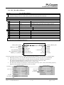
Introduction
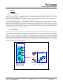
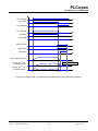
The level of the PLCopen Motion Control Function Blocks are specified at such a level that the user quickly recognizes
the functionality of the function block and what happens if it is activated or connected to other blocks in a sequence of
motion commands. Path oriented movements are programmed either with specific robot oriented programming
languages, or “G-code” (for instance cf. DIN 66025) as used in the CNC world. Both consist of a relative small number
of users. But without a doubt, the movements which can be described in these languages are applicable to a broader
area of use. This PLCopen initiative transforms the functionalities as known in the CNC and Robotic world to the PLC
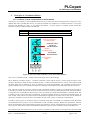
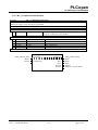
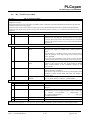
world. With this, an additional part is added to the range of PLCopen Motion Control specifications. The relationship
with the other PLCopen parts is shown below.
y´
PCS
Functions of
PLCopen Part 1 and 2
MCS
SAI
SAI
ACS
SAI
1
Axis group
3
2
SAI = Single Axis
Interpolator
1
2
3
Figure 1: Relationships between the different parts of the PLCopen Motion Control
TC2 - Task Force Motion Control
Part 4 – Coordinated Motion
December 3, 2008
V 1.0
© PLCopen – 2007 - 2008
page 8/ 119
PLCopen
for efficiency in automation
1.3
Overview of the defined Function Blocks
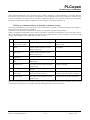
The following table gives an overview of the defined Function Blocks, divided into administrative (not driving motion)
and motion related sets.
Administrative
Motion
Coordinated
Coordinated
Synchronized
MC_AddAxisToGroup
MC_GroupHome
MC_SyncAxisToGroup
MC_RemoveAxisFromGroup
MC_GroupStop
MC_SyncGroupToAxis
MC_UngroupAllAxes
MC_GroupHalt
MC_TrackConveyorBelt
MC_GroupReadConfiguration
MC_GroupInterrupt
MC_TrackRotaryTable
MC_GroupEnable
MC_GroupContinue
MC_GroupDisable
MC_MoveLinearAbsolute
MC_SetKinTransform
MC_MoveLinearRelative
MC_SetCartesianTransform
MC_MoveCircularAbsolute
MC_SetCoordinateTransform
MC_MoveCircularRelative
MC_ReadKinTransform
MC_MoveDirectAbsolute
MC_ReadCartesianTransform
MC_MoveDirectRelative
MC_ReadCoordinateTransform
MC_MovePath
MC_GroupSetPosition
MC_GroupReadActualPosition
MC_GroupReadActualVelocity
MC_GroupReadActualAcceleration
MC_GroupReadStatus
MC_GroupReadError
MC_GroupReset
MC_PathSelect
MC_GroupSetOverride
MC_SetDynCoordTransform
Table 1: Overview of the defined Function Blocks
This specification currently does not support issues like:
• Spline interpolation functionality
• Digital CAM switch on axes group
• Work space monitoring, taking care that the mechanics are not moving outside a certain area (like a standing
pole)
These issues may be covered by future releases.
1.3.1
Length of FB names and ways to shorten them
There are systems that only support a limited number of significant characters in the name. For these rules for shorter
names are provided here. These names are still seen as compliant, although have to be mentioned in the certification
document.
List of rules to shorten names:
Group
Grp
Remove
Rem
Cartesian
Cart
Coordinate
Coord
Transformation
Trans
Kinematic
Kin
Dynamic
Dyn
Synchronized
Sync
Configuration
Cfg
Position
Pos
Velocity
Vel
Acceleration
Acc
TC2 - Task Force Motion Control
Part 4 – Coordinated Motion
December 3, 2008
V 1.0
© PLCopen – 2007 - 2008
page 9/ 119
PLCopen
for efficiency in automation
Linear
Circular
Absolute
Direct
Relative
Actual
Conveyor
Lin
Circ
Abs
Dir
Rel
Act
Conv
Resulting compliant names:
MC_AddAxisToGrp
MC_RemAxisFromGrp
MC_UngroupAllAxes
MC_GrpReadCfg
MC_GrpEnable
MC_GrpDisable
MC_GrpHome
MC_SetKinTrans
MC_SetCartTrans
MC_SetCoordTrans
MC_ReadKinTrans
MC_ReadCartTrans
MC_ReadCoordTrans
MC_GrpReadActPos
MC_GrpReadActVel
MC_GrpReadActAcc
MC_GrpStop
MC_GrpHalt
MC_GrpInterrupt
TC2 - Task Force Motion Control
Part 4 – Coordinated Motion
MC_GrpContinue
MC_GrpReadStatus
MC_GrpReadError
MC_GrpReset
MC_MoveLinAbs
MC_MoveLinRel
MC_MoveCircAbs
MC_MoveCircRel
MC_MoveDirAbs
MC_MoveDirRel
MC_PathSelect
MC_MovePath
MC_GrpSetOverride
MC_SyncAxisToGrp
MC_SyncGrpToAxis
MC_SetDynCoordTrans
MC_TrackConvBelt
MC_TrackRotaryTable
December 3, 2008
V 1.0
© PLCopen – 2007 - 2008
page 10/ 119
PLCopen
for efficiency in automation
1.4
Glossary
Name/ Acronym
ACS
Blending
Contour curve
Coordinate system
Corner deviation
Corner distance
Direction
Drive
Group-FB
MCS
Motor
Orientation
Path
PathData
PCS
Position
Pose (not used)
Scara
Speed
Synchronization
TCP
Tracking
Trajectory
Velocity
Explanation
Axes Coordinate System: The system of coordinates related to the physical motors and the
single movements caused by the single drives.
A way that consecutive function blocks cooperate in the transition from the first to the next.
Inserted curve that modifies the original path. It is the resulting curve after blending.
The reference system in which a coordinate or path is described.
The shortest distance between the programmed corner point and the contour curve.
Distance of the start point of the contour curve to the programmed target point.
The orientational components of a vector in space. (Note: this is different from the
MC_Direction input as used in part 1).
A unit controlling a motor via the current and timing in its coils.
The set of function blocks that can work on a group of axes.
Machine Coordinate System - the system of coordinates that is related to the machine. A
Cartesian coordinate system with the origin in a fixed position relative to the machine (the
origin is defined during the machine setup).
Sometimes called “World Coordinate System” or “Base Coordinate System”.
(Note: with Cartesian build machines, MCS is a Cartesian Coordinate system and may be
identical to ACS, or mapped via a trivial transformation). The coordinate system from the
physical multiple axes ACS is linked to the MCS via a kinematic transformation (forward and
backward conversion). The MCS represents an imaginable space with up to 6 dimensions.
An actuator focused to a movement, converting electrical energy in a force or torque.
The rotational components of a vector in space.
Set of continuous positions and orientation information in multi-dimensional space
Geometrical description of a space curve that the TCP of an axesgroup moves along.
Description of a path which can include additional information like velocity and acceleration.
The coordinate system of the product can be called PCS – Product Coordinate System (or
“Program Coordinate System” in CNC world, or Programmers Coordinate System).
The PCS is based on the MCS typically by shifting and maybe rotating the MCS. The Zero
point of the PCS is related to the product and can be changed during runtime by the program.
The real work piece can have a rotation or shift to the MCS coordinate system or even might
be moving relative to the MCS coordinate system. By specifying a trajectory in PCS one is
able to describe the trajectory independent from the machine situation. To map these two
worlds (MCS to PCS and vice versa), a cartesian or cylindrical transformation is normally
done.
Position means a point in space which is described by different coordinates. Depending on the
used system and transformation it can consist of up to 6 dimensions (coordinates) meaning 3
Cartesian coordinates in space and 3 coordinates for the orientation.
In ACS there can be even more than 6 coordinates.
If the same position is described in different coordinate systems the values of the coordinates
are different.
Position and orientation (DIN EN ISO 8373). Position is used instead in this document.
A special kinematic for robot or handling applications.
Speed is the absolute value of the velocity without direction.
Combines an axis or axes group (as slave) with an axis as master in order that the slave
executes its path with synchronization to the progress of the master, meaning linked to a onedimension source for synchronization.
Tool Centre point, the point in the machine that is commanded to move, typically the center or
the head of the tool. It can be described in different coordinate systems.
Is characterized by an axis group that follows with its movement the movement of another
axis group.
Time dependent description of the path the TCP of an axes group moves along.
Additionally to the geometrical description of the space curve, time dependent state variables
like velocity, acceleration, jerk, forces etc. are specified.
For a group of axes this means:
- in ACS the velocities of the different axes;
TC2 - Task Force Motion Control
Part 4 – Coordinated Motion
December 3, 2008
V 1.0
© PLCopen – 2007 - 2008
page 11/ 119
PLCopen
for efficiency in automation
- in MCS and PCS it provides the velocity of the TCP.
TC2 - Task Force Motion Control
Part 4 – Coordinated Motion
December 3, 2008
V 1.0
© PLCopen – 2007 - 2008
page 12/ 119
PLCopen
for efficiency in automation
2
Principles of Coordinated Motion
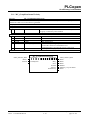
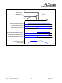
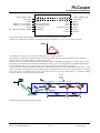
2.1 Coordinate System and kinematic transformation
The essence of a trajectory is the coordinated motion of two or more axes from a starting point to a target point via a
defined path with a specified path velocity. As path one can think of a straight line, a circular movement, or via a spline
function. The definition of a path– or any position information - in space requires a coordinate system. Within this
specification three coordinate systems are defined:
ACS
MCS
PCS
Axis related
Machine related
Product or Workpiece related
Y'
Z'
y´
PCS
X'
Z
MCS
X
Y
ACS
1
Product or Programmer´s
Coordinate System
Cartesian and/or
cylindrical
transformations
Machine
Coordinate System
Kinematical
transformations
Axes Coordinate
System
Axis group
3
2
Figure 2: Overview of the coordinate systems and transformations
ACS: Axes Coordinate System – actual position of the physical axis (after homing).
MCS: Machine Coordinate System – Cartesian coordinate system with the origin is a fixed position relative to the
machine. (Sometimes called “World Coordinate System” or “Base Coordinate System”). (Note: with Cartesian build
machines, MCS may be identical to ACS, or mapped via a trivial transformation). The coordinate system from the
physical multiple axes ACS is linked to the MCS via a kinematic transformation (forward and backward conversion).
PCS: The real work piece can have a rotation or shift to the MCS coordinate system or even might be moving relative
to the MCS coordinate system, and often one wants to describe the trajectory independent from the machine situation.
To map these two worlds (MCS to PCS and vice versa), a cartesian or cylindrical transformation is normally done. The
coordinate system of the product can be called PCS – Product Coordinate System (or “Program Coordinate System” in
CNC world). There can be more than one PCS transformation applicable at the same time. In this case the ENUM to
specify the coordinate system (CS) has to be extended. A PCS can be a static or a dynamic transformation.
In order to specify a point or orientation in space a position always has to be related to a coordinate system. By means
of transformations this position can be transformed to other coordinate systems. Within this specification, function
blocks are defined for these transformations, hiding the complexity of these transformations to the programmer in its
day to day use. All multi axes motion commands are related to only one of the coordinate systems at the same time.
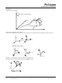
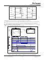
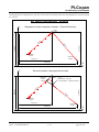
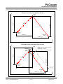
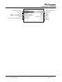
The example below demonstrates how a point P, which is situated on a 2D workpiece (red trapezoid), can be described
TC2 - Task Force Motion Control
Part 4 – Coordinated Motion
December 3, 2008
V 1.0
© PLCopen – 2007 - 2008
page 13/ 119
PLCopen
for efficiency in automation
equivalent in PCS (blue), MCS (black) and ACS (green). Point P could be specified by referring to PCS resulting in the
position PPCS = (xPCS, yPCS). Given the shift and orientation of PCS relative to MCS, point P equivalently could be
specified by PMCS = (xMCS, yMCS). Assuming a SCARA robot with two rotary axes point P also could be described by
the angles of the axes PACS = (φ1, φ2).
yMCS
P
S
y PC
S
x PC
f2
f1
xMCS
f1
f2
(forward) kinematic
transformation
backward / inverse
kinematic transformation
xMCS
yMCS
cartesian / cylindrical
transformation
xPCS
yPCS
Figure 3: Example for specifying point P in PCS, MCS or ACS
assuming a SCARA robot with two rotary axes
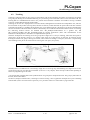
2.1.1
Kinematic Transformation
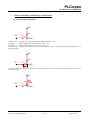
Axes are connected via mechanical links providing movements of the ‘Tool Center Point’, TCP in space. TCP is a
distinguished point of the machine, sometimes also called ‘Point of Interest’, POI, or ‘effector’. The physical assembly
of the axes and therefore the position of the TCP in MCS is described by a so called kinematic transformation. The
kinematic transformation connects ACS to MCS (forward conversion). By applying the kinematic transformation on a
position related to ACS, this position can be transformed into a position in MCS. The other way round, applying the
inverse kinematic transformation, a position related to MCS can be transformed into a position in ACS (backward
conversion).
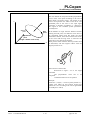
With simple cartesian machine constructions, in which axes are directly oriented in X-, Y-, and Z-directions of MCS,
the kinematic transformation can easily be specified. One just has to define which axis is in the X-direction, which in
Y, and which in the Z-direction. In the simplest case ACS is identically to MCS and one needn’t distinguish between
both. But in praxis there are many non-cartesian structures, like SCARA robots or Tripods, where the kinematic
transformation is more complex.
y
TCP
TCP
ellbow up
ellbow down
x
x
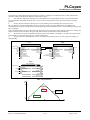
Figure 4: Example for reaching the same position in space
with a) a cartesian handling (2 linear axes) and b) a SCARA (2 rotary axes) with two possible
configurations (elbow down and elbow up). (Note: the orientation is fixed in both examples)
TC2 - Task Force Motion Control
Part 4 – Coordinated Motion
December 3, 2008
V 1.0
© PLCopen – 2007 - 2008
page 14/ 119
PLCopen
for efficiency in automation
Above example demonstrates how a position in space could be reached by a cartesian handling or a SCARA. Whereas
the positions of the linear axes are more or less identical to the coordinates of the position in MCS, the positions of the
axes of the SCARA are not that easy to calculate. Additionally there are two possible solutions of the backward
kinematic transformation, different configurations of the machine: elbow down and elbow up.
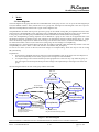
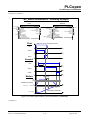
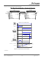
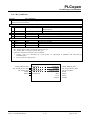
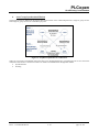
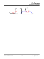
2.2 How do commands behave in dynamic coordinate systems
If the TCP should follow a moving target, this can be achieved by a dynamic coordinate transformation, leading to a
PCS which is moving in relation to the MCS.
The activation of a dynamic transformation is done by activating MC_SetDynCoordTransform.
If there is a dynamic transformation active, the axis may follow the dynamic transformation or stay in the static ACS or
MCS. The following example is showing the behavior. The example describes a robot fetching a screw from a fixed
position and mounting it on a product that is moving on a belt.
Ste
p
1
2
Move command
Axes (group) behavior
Application example
Activating Transformation ACS to MCS
MC_MoveAbsolute in
MCS
Group is staying still (not moving)
Initialization
MCS is static
Moving to standby position and waiting
for products
3
Motion command in
static MCS
4
Motion command in
static MCS
Activating a dynamic
PCS
Motion command in
dynamic PCS
5
6
7
Screwing command
8
Motion command in
static MCS
Motion command in
dynamic PCS
9
Group moves to the commanded
position in MCS and stays in static
MCS (not moving)
Group moves to the commanded
position in MCS and stays in static
MCS (not moving)
Picking command
PCS is active and moves synchronized
with the belt
Group moves to commanded position in
PCS and is moving together with the
dynamic PCS
Group is still following the product on
the belt
Group moves to commanded position in
MCS at the fixed screw box
Group moves to commanded position in
PCS and is moving together with the
dynamic PCS
Moving to a fixed box of screws
Picking up a screw
PCS is ready for use
Placing the screw and following the
product on the belt
Screw is being screwed into the product
Moving to the fixed box of screws and
waiting for the next product on the belt
Placing the screw to the new product
and following the product on the belt
Rule: An axis group stays in the coordinate system which is specified with the last motion command. If this is a PCS
with dynamic transformation, it will follow the PCS (keeping the same position in this PCS).
TC2 - Task Force Motion Control
Part 4 – Coordinated Motion
December 3, 2008
V 1.0
© PLCopen – 2007 - 2008
page 15/ 119
PLCopen
for efficiency in automation
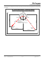
2.3
Movements
Applying a movement on a machine via a function block causes the TCP to move towards the new commanded
position. The kind of function block applied specifies the path via which the new target position is reached. (Note: the
coordinate system in which the new commanded position is specified does not have an influence on the path.)
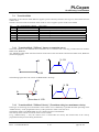
Basically there are two types of movements which have to be distinguished:
Point - to - Point movements, PTP (also referred to as Joint Interpolated Movements):
With this type the essence is to reach the commanded position as fast as possible. This can be achieved by moving each
axis on the shortest way from its starting position to its target position. Usually this kind of movement is the fastest way
to reach a new commanded position, because at any time at least one axis moving at it’s dynamic limit. The path and
the path velocity of the TCP are not important. They are determined by the process of the positions of the axes and the
kinematic transformation of the machine. Therefore this kind of movement is applicable for handlings and whenever
the path of the TCP is not crucial. It is recommended that all axes will arrive at the commanded position at the same
point in time (synchronized).
The applicable Function Blocks as specified herein are:
• MC_MoveDirectAbsolute
• MC_MoveDirectRelative
Cartesian Path movements, CP (also referred to as Continuous Path movements):
CP movements cause the TCP to move along a defined path in Cartesian space. A path can be (a set of) a straight line,
a circular movement, or a spline function. The path via which the new commanded position is reached is important. For
example, this is essential if a workpiece is being processed. Further, the path velocity of the TCP can be controlled
directly. Contrary to joint interpolated movements the process of the position of each axis is determined by the desired
path and the inverse kinematic transformation.
The applicable Function Blocks as specified herein are:
• MC_MoveLinearAbsolute
• MC_MoveLinearRelative
• MC_MoveCircularAbsolute
• MC_MoveCircularRelative
• MC_MovePath
The figure below illustrates the differences between different types of movement by means of a theoretical machine.
axis
position
y
E
S
x
t
Figure 5: Different types of movements
MC_MoveDirect (black), MC_MoveLinear (green) and MC_MoveCircular (blue)
and typical positions of one of the axis of the machine participating in the movement
TC2 - Task Force Motion Control
Part 4 – Coordinated Motion
December 3, 2008
V 1.0
© PLCopen – 2007 - 2008
page 16/ 119
PLCopen
for efficiency in automation
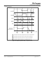
2.4
Blending and Buffering of Movements
2.4.1
General Information
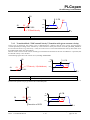
A fundamental part of interpolated motion control is blending of (buffered) consecutive motion commands on an axes
group. Without blending the TCP of an axes group moves towards the commanded position, decelerates and comes to
standstill exactly at the commanded position. The following buffered motion command doesn’t become active until
now. Obviously the axes group has to accelerate again. In many applications a different behaviour of the TCP is
desired and one wants to concatenate movements without stopping.
Reasons for this are:
• Reduction of the process cycle time (e.g. pick and place)
• Generate a smoother movement in order to reduce the mechanical stress
• Some applications demand a constant Velocity of the TCP (e.g. applying glue, painting, welding, etc.)
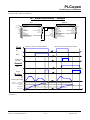
All this can be achieved by different types of blending. Common to all types of blending is a modification of the
original path, resulting in a smooth trajectory without corners.
Blending of motion commands in interpolated motion control differs from blending of motion commands on single
axes. With single axes the commanded position is always reached. Just the velocity at the time when the commanded
position is reached (or passed) can be changed according to the input parameter BufferMode.
With interpolated motion control several types of blending can be thought of, depending on the application and
process. Therefore new types of blending have to be introduced for interpolated motion control.
The input parameter for blending might vary due to the kind of interpolation method applied. So this input is supplier
specific.
The type of inserted curve that modifies the original path (the ‘contour curve’) is not part of this specification and can
be defined by the supplier specific input parameter for blending.
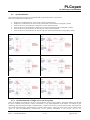
Buffered
without Blending
p2
p3
Aborting
p2
p3
Blending
p2
p3
p4
Trajectory
of TCP
p1
p1
p1
Speed
of TCP
t
t
t
Figure 6: Trajectories and process of Velocity in principle of two
consecutive motion commands in three modes
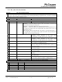
2.4.2
Overview of Buffer Modes
For axes group motions the same buffer modes are used as for single axis motions (ENUM of type
MC_BUFFER_MODE).
No.
0
1
2
3
4
5
MC_BUFFER_MODE
Aborting
Buffered
BlendingLow
BlendingPrevious
BlendingNext
BlendingHigh
Description
Start FB immediately (default mode)
Start FB after current motion has finished
The velocity is blended with the lowest velocity of both FBs
The velocity is blended with the velocity of the first FB
The velocity is blended with velocity of the second FB
The velocity is blended with highest velocity of both FBs
Table 2: Overview of Buffer Modes
For details refer to Chapter 77 - Details of Blending and Buffering of Movements.
TC2 - Task Force Motion Control
Part 4 – Coordinated Motion
December 3, 2008
V 1.0
© PLCopen – 2007 - 2008
page 17/ 119
PLCopen
for efficiency in automation
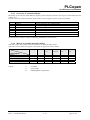
2.4.3
Overview of Transition Modes
Depending on the transition mode different supplier specific transition parameters can be given, which characterize the
contour curve.
The basic transition modes are defined. Other modes as well as supplier specific modes can be added.
No.
0
1
2
3
4
5-9
10 -…
MC_TRANSITION_MODE
Description
TMNone
Insert no transition curve (default mode)
TMStartVelocity
Transition with given start velocity
TMConstantVelocity
Transition with given constant velocity
TMCornerDistance
Transition with given corner distance
TMMaxCornerDeviation
Transition with given maximum corner deviation
Reserved by PLCopen
Supplier specific modes
Table 3: Overview of Transition Modes
For details refer to Chapter 7 Details of Blending and Buffering of Movements.
2.4.4
Matrix of available transition modes
This matrix shows the available transition modes for the different buffer modes.
This matrix can be used by the supplier to document its supported transition modes.
BufferMode Aborting
TransitionMode
TMNone
TMMaxVelocity
TMDefinedVelocity
TMCornerDistance
TMMaxCornerDeviation
Legend:
Buffered
Blending
Low
Blending
Previous
A
A
N
N
D
D
D
D
A
N
A
A
N
N
A
A
N
N
A
A
Table 4: Matrix of available transition modes
A
N
D
TC2 - Task Force Motion Control
Part 4 – Coordinated Motion
Blending
Next
Blending
High
N
D
A
A
A
N
D
A
A
A
= Available
= Not possible
= BlendingMode is dispensable
December 3, 2008
V 1.0
© PLCopen – 2007 - 2008
page 18/ 119
PLCopen
for efficiency in automation
3
Model
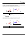
3.1 State diagram
The state-diagram of the group describes the commanded state of the group of axes. It is on top of the state diagram per
axis (like defined in Parts 1 and 2). While axes are in a group state, the single axis state diagram is also active per axis.
Therefore interdependencies between the 2 types of state-diagrams exist.
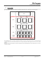
GroupDisabled is the initial state at power up where a group can be created. Issuing MC_GroupEnable leaves this state.
The next state is GroupStandby. In this state the group is enabled and no function block has control on one of the axes
in the group. In this state the group can additionally be altered and homed if needed (State GroupHoming).
In the state GroupHoming a homing sequence can be defined for a group of axis. This can be applicable due to the
mechanical constraints of multiple motors (for example in an mechanical construct looking like the letter “I“ with 2
motor mechanically coupled via one band or belt moving over the form of the letter I, need to be homed differently.).
If a function block has control on (one of the axis of) the group, the state changes to GroupMoving.
GroupStopping is a special state that deals with the MC_GroupStop command, which automatically tranfers to the state
GroupStandby as soon as “Done” is SET and “Execute” is FALSE in MC_GroupStop.
In case an error arises (in one of the axis) the state changes to GroupErrorStop, which can only be left via issuing
MC_ResetGroup.
Explanations:
Group motion commands will always lead to a SynchronizedMotion state in the single axis state diagram. In
case of a GroupStandby all axes of the group are also in single axis state StandStill.
A GroupErrorStop will not lead to ErrorStops of the grouped axes as the error may only affect the group. In
case of a single axis ErrorStop the Group will also change to GroupErrorStop as the single error effects the
group.
The state diagram reflects the state of the group and the issued FBs..
Note 1 and
MC_GroupHalt
GroupMoving
MC_GroupStop
Note2
MC_GroupStop
GroupStopping
Error
Done
Note1
Error
GroupHoming
Note2
p
Sto
Done
MC
p
rou
_G
Note 3
Error
GroupErrorStop
MC_GroupHome
Error
MC_GroupEnable
GroupStandby
GroupDisabled
MC_GroupReset
MC_GroupDisable
MC_UngroupAllAxes
MC_RemoveAxisFromGroup
(Note 4)
MC_AddAxisToGroup
MC_RemoveAxisFromGroup
MC_UngroupAllAxes
MC_AddAxisToGroup
MC_RemoveAxisFromGroup (Note 5)
Figure 7: The State Diagram
Note to transitions: Continuous lines are commanded transitions; dotted lines are automatic transitions.
TC2 - Task Force Motion Control
Part 4 – Coordinated Motion
December 3, 2008
V 1.0
© PLCopen – 2007 - 2008
page 19/ 119
PLCopen
for efficiency in automation
Note 1: Applicable for all non-administrative (moving) function blocks.
Note 2: In the states GroupErrorStop or GroupStopping, all Function Blocks can be called, although they will not be
executed, except MC_GroupReset for GroupErrorStop and any occurring Error– they will generate the transition to
GroupStandby or GroupErrorStop respectively
Note 3: MC_GroupStop.DONE AND NOT MC_GroupStop.EXECUTE
Note 4: Transition is applicable if last axis is removed from the group
Note 5: Transition is applicable while group is not empty.
Note 6: MC_GroupDisable and MC_UngroupAllAxes can be issued in all states and will change the state to
GroupDisabled.
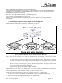
3.2
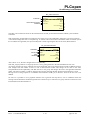
Relationship Single Axis and Grouped Axes State Diagrams
Example of the relationship between 3 single axes combined in an axes group.
Group state diagram
S
S
Single axis state diagrams
Figure 8: Relationship Single Axis and Grouped Axes State Diagrams
When a number of axes are grouped, and a single axis command, like MC_MoveAbsolute, is issued to an axis in this
group, there are basically 3 options:
1.
2.
3.
Not allowed. Issuing a single axis command is not accepted and not performed: it signals this by setting the
error output of the applicable (issued) single axis function block. There is no change to the group, and as such
continues their movements.
Aborting the current group command(s), as well as following group commands, and continue with the single
axis command only. The remaining axes of the group move to the state StandStill (via an implicit MC_Halt
per axis). The original trajectory will not be finalized.
Superimpose the single axis commands to the group commands.
This specification does not restrict to any of these options. This means that different implementations of this behavior
will exists, and the supplier of the system has to specify what their system does support.
General rules for the interaction between a single axis towards its groups (for all 3 options above):
• If at least one axis in the group is moved by a command then the group is in the state GroupMoving.
• If all axes are in StandStill, the group can be in the state GroupStandby, GroupDisabled or GroupErrorStop.
• If one axis in a group is in ErrorStop, the whole group is in GroupErrorStop.
TC2 - Task Force Motion Control
December 3, 2008
© PLCopen – 2007 - 2008
Part 4 – Coordinated Motion
V 1.0
page 20/ 119
PLCopen
for efficiency in automation
•
•
•
If a single axis MC_Home is issued the group is in state GroupMoving.
If a single axis MC_Stop is issued the group is in state GroupMoving.
If supported by the system, it is allowed to disable a single axis of the axis group without influencing the axes
group state. This can be useful to save energy or to apply a mechanical brake for a single axis not involved in the
on-going motion.
General rules for the interaction between a group and the single axis in it (for all 3 options above):
• If the group is commanded by a group moving command, all the single axes in the group are in the state
SynchronizedMotion
• If the group is in the state GroupStandby, the states of the single axes do not have to be all in StandStill
• If the group is in the state GroupErrorStop the state of the single axis is not affected
Overview of the influence of group motion commands on a single axis state:
Command
Group State
Axis state
MC_MoveLinearXxx
MC_MoveCircularXxx
MC_MoveDirectXxx
MC_MovePath
MC_GroupHalt
MC_TrackConveyorBelt
MC_TrackRotaryTable
MC_GroupStop
GroupMoving
SynchronizedMotion
GroupStopping / GroupStandby
SynchronizedMotion / StandStill
MC_GroupReset
GroupErrorStop / GroupStandby
Not relevant for Axis
MC_GroupHome
GroupHoming
SynchronizedMotion
Table 5: Overview of the influence of group motion commands on a single axis state
Explanation: A stopping group leaves the single axis in synchronized motion as none of the single axis performs a
single axis stop.
3.3
Input Execution Mode
The input MC_EXECUTION_MODE is an ENUM providing information on the behavior of administrative function
blocks.
The modes are:
• Immediately - the functionality is immediately valid and may influence the on-going motion but not the state
• Delayed - The functionality is valid when the ongoing motion command sets one of the following output
parameters: Done, Aborted or Error. This also implies that the output parameter Busy is set to FALSE.
• Queued - The new functionality becomes valid when all previous motion commands sets one of the following
output parameters: Done, Aborted or Error. This also implies that the output parameter Busy is set to FALSE.
TC2 - Task Force Motion Control
Part 4 – Coordinated Motion
December 3, 2008
V 1.0
© PLCopen – 2007 - 2008
page 21/ 119
PLCopen
for efficiency in automation
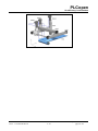
4
Axes Grouping
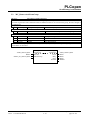
Within this specification for interpolation, the related axes are grouped in an “AxesGroup”, and can be accessed via the
type AXES_GROUP_REF. The relationship between the different axis levels and groups is shown hereunder.
Machine
AxesGroup
PCS
X'
Y'
Z'
Transform
X
MCS
Y
Z
Transform
ACS
Physical
Motors
A1
A2
A3
A4
A5
M1
M2
M3
M4
M5
AxesGroup
Figure 9: Overview AxesGroup
The AxesGroup shown in red above provides the interface to the user of the group of axes. To access the relevant
coordinate system, the relevant function blocks have an input CoordSystem which supports the three levels ACS, MCS
and PCS.
Parameters in the AxesGroupRef can include remaining time and remaining distance before target position (or velocity
or equal) is reached.
TC2 - Task Force Motion Control
Part 4 – Coordinated Motion
December 3, 2008
V 1.0
© PLCopen – 2007 - 2008
page 22/ 119
PLCopen
for efficiency in automation
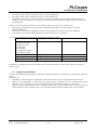
4.1
Creating and using an AxesGroup
In order to create a group, one can go through the following steps:
1. If necessary, move the first axis (or all axes) to the relevant position(s) via single axis commands
2. Give the group a name (create a variable of type AXES_GROUP_REF). Group now in state GroupDisabled.
3. Add the first axis to this group via MC_AddAxisToGroup
4. Repeat this till all axes are defined in the group in the right order
5. Link the kinematic model to the group via MC_SetKinTransform even if it is per default a Cartesian system
6. Link the next level(s) of transformation(s) to the group via MC_SetCartesianTransform and /or
MC_SetCoordinateTransform
7. Enable the group (via MC_GroupEnable) in order to use it.
Example
If not done per axis yet, one switches on the power, and does a homing sequence per relevant axis with the single axis
function blocks. These relevant axes are now in the single axis state StandStill. (Note: It can be that the homing must
(additionally) be done in the group itself, due to special constructional constraints).
One creates a group by adding the first axis to it, and giving it a name. For instance:
MC_AddAxisToGroup
MC_AddAxisToGroup
Cartesian1
AxisX
AxesGroup
AxesGroup
Axis
Execute
1
Cartesian1
AxisX
Axis
Busy
IdentInGroup
Active
Error
ErrorID
MC_AddAxisToGroup with a group name Cartesian1 for AxesGroupRef. The used Axis is referenced via AxisRef,
like AxisX. The input IdentInGroup gives the reference in the group, like 1.
Now a group has been created, called Cartesian1, with one Axis, AxisX, coupled in position 1. The state is still
GroupDisabled.
Now we add a second axis, called AxisY, in position 2, and a third axis, AxisZ, in position 3.
MC_AddAxisToGroup
MC_AddAxisToGroup
MC_AddAxisToGroup
Cartesian1
AxisX
AxesGroup
Axis
Execute
1
IdentInGroup
MC_AddAxisToGroup
AxesGroup
Axis
AxesGroup
AxisY
Busy
Active
AxesGroup
Axis
Axis
Execute
2
Busy
IdentInGroup
Active
Error
Error
ErrorID
ErrorID
MC_AddAxisToGroup
MC_AddAxisToGroup
AxesGroup
AxisZ
Axis
Execute
3
IdentInGroup
AxesGroup
Axis
Busy
Active
Error
ErrorID
The group now consists of 3 axes, with all axes in the state GroupDisabled.
The next step is linking the transformations to this group. For instance, for the kinematic transformation we use
MC_SetKinTransform.
TC2 - Task Force Motion Control
Part 4 – Coordinated Motion
December 3, 2008
V 1.0
© PLCopen – 2007 - 2008
page 23/ 119
PLCopen
for efficiency in automation
MC_SetKinTransform
MC_SetKinTransform
Cartesian1
AxesGroup
AxesGroup
Execute
KinematicTransform
Buffered
D one
KinT ransform
Busy
Bufferm ode
Active
Com m andAborted
Error
ErrorID
The other relevant function blocks for the transformations are MC_SetCartesianTransform and MC_SetCoordinateTransform.
With issuing MC_GroupEnable we transfer the state of the group to GroupStandby, enabling it to accept movements.
A movement changes the state to GroupMoving. To tell the relevant movement command in which coordinate system
the coordinates are applicable, the input CoordSystem is used, supporting the three levels ACS, MCS and PCS.
MC_MoveDirectAbsolute
MC_MoveDirectAbsolute
Cartesian1
AxesGroup
AxesGroup
Execute
100,20,30
PCS
Buffered
Done
Position
Busy
CoordSystem
Buffermode
Active
CommandAborted
Error
ErrorID
After “Done” is set, the state changes back to GroupStandby.
With MC_UngroupAllAxes we ungroup all axes at once, getting them all to the state StandStill for each axis.
An existing AxesGroup can be changed. This can be applicable with a tool change which includes an additional motor.
This changes both the number of axes as well as the kinematic model. The change can be done in the states
GroupDisabled and GroupStandby, and adds the axis to the group and changes the link to the applicable kinematic
model. The same procedure is valid for changing the tool back, although the MC_RemoveAxisFromGroup is used.
Having an axis in the group that is not linked to the kinematics model (yet) is allowed - however the use case is not
defined.
Of course it is possible to use a graphical software tool to generate the steps above, even in a different sense like
starting from the kinematics model and generate the software steps to create the axes group with the connections to the
transformations like described above.
TC2 - Task Force Motion Control
Part 4 – Coordinated Motion
December 3, 2008
V 1.0
© PLCopen – 2007 - 2008
page 24/ 119
PLCopen
for efficiency in automation
5
Function Blocks for Coordinated Motion
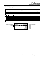
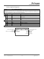
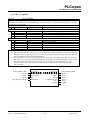
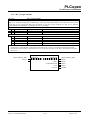
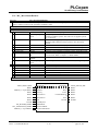
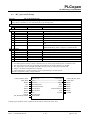
5.1 MC_AddAxisToGroup
FB-Name
MC_AddAxisToGroup
This Function Block adds one axis to a group in a structure AxesGroup. This is an administrative FB, since no
movement is generated. The command cannot be buffered.
VAR_IN_OUT
B
AxesGroup
AXES_GROUP_REF
Reference to a group of axes
B
Axis
AXIS_REF
Reference to the axis to be added
VAR_INPUT
B
Execute
BOOL
Start the grouping process at the rising edge
E
IdentInGroup IDENT_IN_GROUP_REF Identifies the order in the group of the added axis. Done
via a REF in order to give the different axes a name in the
order, which can be coupled to the names in the kinematic
model (like “foot”, “shoulder”)
VAR_OUTPUT
B
Done
BOOL
AXES_GROUP_REF is valid and the axis added
E
Busy
BOOL
The FB is not finished
B
Error
BOOL
Signals that an error has occurred within the function block
E
ErrorID
WORD
Error identification
Note: Each IdentInGroup can be used only once, otherwise it leads to an error
AXES_GROUP_REF
AXIS_REF
BOOL
IDENT_IN_GROUP_REF
TC2 - Task Force Motion Control
Part 4 – Coordinated Motion
MC_AddAxisToGroup
AxesGroup
AxesGroup
Axis
Axis
Execute
Done
IdentInGroup
Busy
Error
ErrorID
December 3, 2008
V 1.0
AXES_GROUP_REF
AXIS _REF
BOOL
BOOL
BOOL
WORD
© PLCopen – 2007 - 2008
page 25/ 119
PLCopen
for efficiency in automation
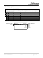
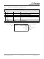
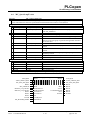
5.2
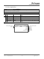
MC_RemoveAxisFromGroup
FB-Name
MC_RemoveAxisFromGroup
This Function Block removes one axis from the group AxesGroup. This is an administrative FB, since no
movement is generated. The command cannot be buffered. If there is no axis left in the group, the state changes to
GroupDisabled.
VAR_IN_OUT
B
AxesGroup
AXES_GROUP_REF
Reference to a group of axes
VAR_INPUT
B
Execute
BOOL
Start the axis removal process at the rising edge
E
IdentInGroup IDENT_IN_GROUP_REF Identifies the axis in the group
VAR_OUTPUT
B
Done
BOOL
AXES_GROUP_REF is valid and the axis removed
E
Busy
BOOL
The FB is not finished
B
Error
BOOL
Signals that an error has occurred within the function block
E
ErrorID
WORD
Error identification
Notes: If issued on a group that is not in GroupDisabled, GroupStandby or GroupErrorStop, it generates an error
and the FB is not executed.
AXES_GROUP_REF
BOOL
IDENT_IN_GROUP_REF
TC2 - Task Force Motion Control
Part 4 – Coordinated Motion
MC_RemoveAxisFromGroup
AxesGroup
AxesGroup
Execute
Done
IdentInGroup
Busy
Error
ErrorID
December 3, 2008
V 1.0
AXES_GROUP_REF
BOOL
BOOL
BOOL
WORD
© PLCopen – 2007 - 2008
page 26/ 119
PLCopen
for efficiency in automation
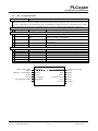
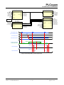
5.3
MC_UngroupAllAxes
FB-Name
MC_UngroupAllAxes
This Function Block removes all axes from the group AxesGroup. This is an administrative FB, since no
movement is generated. The command cannot be buffered. After finalization the state is changed to
GroupDisabled
VAR_IN_OUT
B
AxesGroup
AXES_GROUP_REF Reference to a group of axes
VAR_INPUT
B
Execute
BOOL
Start the process at the rising edge
VAR_OUTPUT
B
Done
BOOL
All axes are removed
E
Busy
BOOL
The FB is not finished
B
Error
BOOL
Signals that an error has occurred within the function block
E
ErrorID
WORD
Error identification
Notes: If issued on a group that is not in GroupDisabled, GroupStandby or GroupErrorStop, it generates an error
and the FB is not executed.
AXES_GROUP_REF
BOOL
TC2 - Task Force Motion Control
Part 4 – Coordinated Motion
MC_UngroupAllAxes
AxesGroup
AxesGroup
Execute
Done
Busy
Error
ErrorID
December 3, 2008
V 1.0
AXES_GROUP_REF
BOOL
BOOL
BOOL
WORD
© PLCopen – 2007 - 2008
page 27/ 119
PLCopen
for efficiency in automation
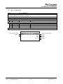
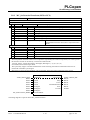
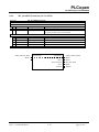
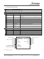
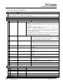
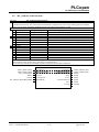
5.4 MC_GroupReadConfiguration
FB-Name
MC_GroupReadConfiguration
This Function Block gets the axis reference according to the given group identifier in order to read the current
configuration of an axes group. For CoordSystem-Input “ACS” you get a conventional axis reference, but for
CoordSystem-Input “MCS” or “PCS” you get the axis reference of a virtual axis according to the transformation that is
active. This is an administrative FB, since no movement is generated.
VAR_IN_OUT
B AxesGroup
AXES_GROUP_REF
Reference to the group of axes
VAR_INPUT
B Enable
BOOL
Gets the axis reference according to the given group identifier
while enabled
B IdentInGroup IDENT_IN_GROUP_REF Identifies the axis in the group
E
CoordSystem ENUM
Reference to the applicable coordinate system: ACS, MCS,
PCS
VAR_OUTPUT
B Axis
AXIS_REF
Reference to the selected axis
B Valid
BOOL
True if valid outputs are available
E
Busy
BOOL
The FB is not finished
B Error
BOOL
Signals that an error has occurred within the function block
E
ErrorID
WORD
Error identification
Notes: -
AXES_GROUP_REF
BOOL
IDENT_IN_GROUP_REF
ENUM
TC2 - Task Force Motion Control
Part 4 – Coordinated Motion
MC_GroupReadConfiguration
AxesGroup
AxesGroup
Enable
Axis
IdentInGroup
Valid
CoordSystem
Busy
Error
ErrorID
December 3, 2008
V 1.0
AXES_GROUP_REF
AXIS_REF
BOOL
BOOL
BOOL
WORD
© PLCopen – 2007 - 2008
page 28/ 119
PLCopen
for efficiency in automation
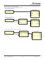
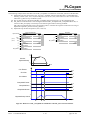
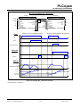
Examples on how to use this function block:
1. Conventional single axis motion Æ a single axis is moved
Conventional programming
MC_MoveVelocity
PLCO_Axis
MC_MoveVelocity
Axis
Axis
Axis
Execute
InVelocity
Busy
Velocity
Acceleration
Active
Deceleration
CommandAborted
Error
Jerk
ErrorID
Direction
Buffermode
Alternative programming
MC_GroupReadConfiguration
PLCO_AxesGroup
MC_MoveVelocity
MC_GroupReadConfiguration
AxesGroup
AxesGroup
MC_MoveVelocity
AxesGroup
Axis
1
AxisIndex 0
ACS
Axis
Axis
Enable
Valid
Execute
IdentInGroup
Busy
Velocity
Error
Acceleration
Active
ErrorID
Deceleration
CommandAborted
CoordinateSystem
InVelocity
Busy
Error
Jerk
ErrorID
Direction
Buffermode
2. Virtual single axis motion Æ a path axis is moved
MC_GroupReadConfiguration
PLCO_AxesGroup
MC_MoveVelocity
MC_GroupReadConfiguration
AxesGroup
AxesGroup
Axis
1
AxisIndex 0
MCS
1Enable
IdentInGroup
CoordinateSystem
MC_MoveVelocity
AxesGroup
Axis
Axis
Valid
Execute
Busy
Velocity
Error
Acceleration
Active
ErrorID
Deceleration
CommandAborted
InVelocity
Busy
Jerk
Direction
Buffermode
TC2 - Task Force Motion Control
Part 4 – Coordinated Motion
December 3, 2008
V 1.0
© PLCopen – 2007 - 2008
page 29/ 119
Error
ErrorID
PLCopen
for efficiency in automation
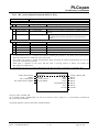
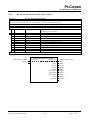
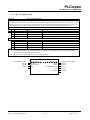
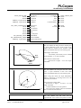
5.5
MC_GroupEnable
FB-Name
MC_GroupEnable
This Function Block changes the state for a group from GroupDisabled to GroupStandby. This is an
administrative FB, since no movement is generated.
VAR_IN_OUT
B
AxesGroup
AXES_GROUP_REF
Reference to a group of axes
VAR_INPUT
B
Execute
BOOL
Start the change of state at the rising edge
VAR_OUTPUT
B
Done
BOOL
AxesGroup in state GroupStandby
E
Busy
BOOL
The FB is not finished
B
Error
BOOL
Signals that an error has occurred within the function block
E
ErrorID
WORD
Error identification
Note: The command does not influence the power state of any of the single axes in the group
AXES_GROUP_REF
BOOL
TC2 - Task Force Motion Control
Part 4 – Coordinated Motion
MC_GroupEnable
AxesGroup
AxesGroup
Execute
Done
Busy
Error
ErrorID
December 3, 2008
V 1.0
AXES_GROUP_REF
BOOL
BOOL
BOOL
WORD
© PLCopen – 2007 - 2008
page 30/ 119
PLCopen
for efficiency in automation
5.6
MC_GroupDisable
FB-Name
MC_GroupDisable
This Function Block changes the state for a group to GroupDisabled, although it is an administrative FB, since no
movement is generated. If the axes are not standing still while issuing this command, it is up to the application to
take the necessary precautions.
VAR_IN_OUT
B
AxesGroup
AXES_GROUP_REF Reference to a group of axes
VAR_INPUT
B
Execute
BOOL
Start the change of state at the rising edge
VAR_OUTPUT
B
Done
BOOL
AxesGroup in state GroupDisabled
E
Busy
BOOL
The FB is not finished
B
Error
BOOL
Signals that an error has occurred within the function block
E
ErrorID
WORD
Error identification
Note: The command does not influence the power state of any of the single axes in the group
AXES_GROUP_REF
BOOL
TC2 - Task Force Motion Control
Part 4 – Coordinated Motion
MC_GroupDisable
AxesGroup
AxesGroup
Execute
Done
Busy
Error
ErrorID
December 3, 2008
V 1.0
AXES_GROUP_REF
BOOL
BOOL
BOOL
WORD
© PLCopen – 2007 - 2008
page 31/ 119
PLCopen
for efficiency in automation
5.7
MC_GroupHome
FB-Name
MC_GroupHome
This Function Block commands the AxesGroup to perform the «search home» sequence. The details of this sequence
are manufacturer dependent and can be set by the axis’ parameters. The “Position” input is used to set the absolute
position when reference signal is detected. This Function Bock completes at “GroupStandby”.
VAR_IN_OUT
B AxesGroup
AXES_GROUP_REF
Reference to a group of axes
VAR_INPUT
B Execute
BOOL
Start the homing sequence at the rising edge
B Position
ARRAY [1..N] OF REAL Array of coordinates incl. Positions and orientations
E CoordSystem
ENUM
Reference to the applicable coordinate system: ACS, MCS, PCS
E BufferMode
MC_BUFFER_MODE
Buffer mode. Modes “Aborting” and “Buffered” are useful. All
other modes should act like “Buffered”.
VAR_OUTPUT
B Done
BOOL
Homing sequence ended successfully
E Busy
BOOL
The FB is not finished
E Active
BOOL
Indicates that the FB is processed
E CommandAborted BOOL
Command is aborted by another command
B Error
BOOL
Signals that an error has occurred within the function block
E ErrorID
WORD
Error identification
Note: If you issue this FB with BufferMode “Aborting” outside the state GroupStandby, an error is generated.
AXES_GROUP_REF
BOOL
ARRAY [1..N] OF REAL
ENUM
MC_BUFFER_MODE
TC2 - Task Force Motion Control
Part 4 – Coordinated Motion
MC_GroupHome
AxesGroup
AxesGroup
Execute
Done
Position
Busy
CoordSystem
Active
BufferMode
CommandAborte
d
Error
ErrorID
December 3, 2008
V 1.0
AXES_GROUP_REF
BOOL
BOOL
BOOL
BOOL
BOOL
WORD
© PLCopen – 2007 - 2008
page 32/ 119
PLCopen
for efficiency in automation
5.8
Transformation FBs
This chapter provides an overview of the transformation function blocks. Although they are administrative FBs, the
transformation FBs can be buffered.
5.8.1
MC_SetKinTransform (ACS to MCS)
FB-Name
MC_SetKinTransform
This Function Block sets a kinematic transformation between the ACS and MCS based on the predefined kinematic
model.
VAR_IN_OUT
B AxesGroup
AXES_GROUP_REF Reference to a group of axes
VAR_INPUT
B Execute
BOOL
Sets the kinematic model transformation on rising edge
E
KinTransform
MC_KIN_REF
Reference to a Kinematic Model. Vendor specific datatype.
E
ExecutionMode MC_EXECUTION_MO Describes when the command is executed and the new
DE
transformation becomes valid. (See 3.3 Input Execution
Mode)
VAR_OUTPUT
B Done
BOOL
Transformation is set successfully
E
Busy
BOOL
The FB is not finished
E
Active
BOOL
Indicates that the FB is processed
E
CommandAborted BOOL
Command is aborted by another command
B Error
BOOL
Signals that an error has occurred within the function block
E
ErrorID
WORD
Error identification
Notes:
• A kinematic transformation is a representation of the machine construction. For kinematically simple machine
constructions, like a three axes Cartesian robot, a kinematic transformation may not be necessary.
• The input KinTransform refers to a kinematic model including the parameters. The details of the kinematic model
and of the parameters are outside the scope of PLCopen.
• The system may support a neutral KinTransform. With activating the neutral transformation the axes are
referenced in the ACS system again.
• The FB always acts on a pre-defined AxesGroup. Since a kinematic transformation always has to fit to an
appropriate AxesGroup, a call to this FB will lead to an error unless an appropriate AxesGroup is defined.
AXES_GROUP_REF
BOOL
MC_KIN_REF
MC_EXECUTION_MODE
TC2 - Task Force Motion Control
Part 4 – Coordinated Motion
MC_SetKinTransform
AxesGroup
AxesGroup
Execute
Done
KinTransform
Busy
ExecutionMode
Active
CommandAborted
Error
ErrorID
December 3, 2008
V 1.0
AXES_GROUP_REF
BOOL
BOOL
BOOL
BOOL
BOOL
WORD
© PLCopen – 2007 - 2008
page 33/ 119
PLCopen
for efficiency in automation
Timing Diagram:
Figure 10: Typical timing diagram for setting the transformation
TC2 - Task Force Motion Control
Part 4 – Coordinated Motion
December 3, 2008
V 1.0
© PLCopen – 2007 - 2008
page 34/ 119
PLCopen
for efficiency in automation
5.8.2
MC_SetCartesianTransform (MCS to PCS)
FB-Name
MC_SetCartesianTransform
This Function Block sets a Cartesian transformation between the MCS and PCS.
VAR_IN_OUT
B AxesGroup AXES_GROUP_REF Reference to a group of axes
VAR_INPUT
B Execute
BOOL
Sets the cartesian transformation on rising edge
B TransX
REAL
X-component of Translation Vector
B TransY
REAL
Y-component of Translation Vector
B TransZ
REAL
Z-component of Translation Vector
B RotAngle1
REAL
Rotation angle component
B RotAngle2
REAL
Rotation angle component
B RotAngle3
REAL
Rotation angle component
E
ExecutionMode
MC_EXECUTION_MODE Describes when the command is executed and the new
transformation becomes valid. (See 3.3 Input Execution
Mode).
VAR_OUTPUT
B Done
BOOL
Transformation is set successfully
E
Busy
BOOL
The FB is not finished
E
Active
BOOL
Indicates that the FB is processed
E
CommandAborted BOOL
Command is aborted by another command
B Error
BOOL
Signals that an error has occurred within the function block
E
ErrorID
WORD
Error identification
Notes:
• The interpretation and order of the vector components (specifically the rotation components) are vendor specific
• De-selection of PCS can be done by a execution of this FB with
{TransX, TransY, TransZ, RotAngle1, RotAngle2, RotAngle3 }={0, 0, 0, 0, 0, 0}
as translation and rotation input values.
• The system may support a neutral transformation. With activating the neutral transformation the axes are
referenced in the MCS system again.
• More then one cartesian transformation can be applicable at the same time on the same group of axes.
AXES_GROUP_REF
BOOL
REAL
REAL
REAL
REAL
REAL
REAL
MC_EXECUTION_MODE
MC_SetCartesianTransforms
AxesGroup
AxesGroup
Execute
Done
TransX
Busy
TransY
Active
TransZ
CommandAborted
RotAngle1
Error
RotAngle2
ErrorID
RotAngle3
ExecutionMode
AXES_GROUP_REF
BOOL
BOOL
BOOL
BOOL
BOOL
WORD
The timing diagram is equal to that of MC_SetKinTransform
TC2 - Task Force Motion Control
Part 4 – Coordinated Motion
December 3, 2008
V 1.0
© PLCopen – 2007 - 2008
page 35/ 119
PLCopen
for efficiency in automation
Explanation:
Definition of the translation:
z
MCS
Cartesian Machine Coordinate System
MCS
z´
y´
y
PCS
TransZ
MCS
x´
TransX
an
Tr
sY
x MCS
Example of the definition of the rotation:
The rotation is defined by a subsequent rotation around every coordinate direction beginning with the Z-direction.
z´´´
z
Trans
y´´´
x´´´
x
Definition of the rotation:
z´ = z
z´´ z´
z´´
z´´´
RotZ
y´
y
y´´´
y´´
y´´= y´
RotY
RotX
x
x´´
x´
x´
Example: Use of the FB for a rotation in the plane (2-dimensions):
Execution of MC_SetCartesianTransform with: {50,50,0,0,0,30}
x´´´= x´´
Y
TransY
RotZ
TransX
X
TC2 - Task Force Motion Control
Part 4 – Coordinated Motion
December 3, 2008
V 1.0
© PLCopen – 2007 - 2008
page 36/ 119
PLCopen
for efficiency in automation
5.8.3
MC_SetCoordinateTransform (MCS to PCS)
FB-Name
MC_SetCoordinateTransform
This Function Block sets a coordinate transformation between the MCS and PCS.
VAR_IN_OUT
B AxesGroup
AXES_GROUP_REF
Reference to a group of axes
VAR_INPUT
B Execute
BOOL
Sets the coordinate transformation on rising edge
E
CoordTransform MC_COORD_REF
Reference to a Coordinate Transformation. Vendor specific
datatype.
E
ExecutionMode MC_EXECUTION_MODE Describes when the command is executed and the new
transformation becomes valid. (See 3.3 Input Execution
Mode).
VAR_OUTPUT
B Done
BOOL
Transformation is set successfully
E
Busy
BOOL
The FB is not finished
E
Active
BOOL
Indicates that the FB is processed
E
CommandAborted BOOL
Command is aborted by another command
B Error
BOOL
Signals that an error has occurred within the function block
E
ErrorID
WORD
Error identification
Notes:
• CoordTransform refers to a coordinate transformation including the parameters. The details of the transformation
and of the parameters are outside the scope of PLCopen.
• The system may support a neutral transformation. With activating the neutral transformation the axes are
referenced in the MCS system again..
• When PCS is dynamic (in the sense that the PCS is moving relative to MCS), one should use
MC_SetDynCoordTransform.
• This FB does not start a movement (administrative FB). The movement is initiated by a command in PCS.
AXES_GROUP_REF
BOOL
MC_COORD_REF
MC_EXECUTION_MODE
MC_SetCoordinateTransform
AxesGroup
AxesGroup
Execute
Done
CoordTransform
Busy
ExecutionMode
Active
CommandAborted
Error
ErrorID
AXES_GROUP_REF
BOOL
BOOL
BOOL
BOOL
BOOL
WORD
Example of MC_COORD_REF
As an example of MC_COORD_REF, one can use a structure of the 6 inputs X, Y, Z, and rotations as defined in
MC_SetCartesianTransforms.
The timing diagram is equal to that of MC_SetKinTransform
TC2 - Task Force Motion Control
Part 4 – Coordinated Motion
December 3, 2008
V 1.0
© PLCopen – 2007 - 2008
page 37/ 119
PLCopen
for efficiency in automation
5.8.4
MC_ReadKinTransform (ACS to MCS)
FB-Name
MC_ReadKinTransform
This Function Block reads the kinematic transformation that is active between the ACS and MCS.
VAR_IN_OUT
B AxesGroup
AXES_GROUP_REF Reference to a group of axes
VAR_INPUT
B Enable
BOOL
Get the actual kinematic transformation reference of the
axes group continuously while enabled
VAR_OUTPUT
B Valid
BOOL
True if valid outputs are available
E
Busy
BOOL
The FB is not finished
B KinTransform MC_KIN_REF
Reference to a Kinematic Model. Vendor specific datatype.
B Error
BOOL
Signals that an error has occurred within the function block
E
ErrorID
WORD
Error identification
Notes:
AXES_GROUP_REF
BOOL
TC2 - Task Force Motion Control
Part 4 – Coordinated Motion
MC_ReadKinTransform
AxesGroup
AxesGroup
Enable
Valid
Busy
KinTransform
Error
ErrorID
December 3, 2008
V 1.0
AXES_GROUP_REF
BOOL
BOOL
MC_KIN_REF
BOOL
WORD
© PLCopen – 2007 - 2008
page 38/ 119
PLCopen
for efficiency in automation
5.8.5
MC_ReadCartesianTransform (MCS to PCS)
FB-Name
MC_ReadCartesianTransform
This Function Block reads the parameter of the cartesian transformation that is active between the MCS and PCS. If
more than one transformation is active, the resulting cartesian transformation is given.
VAR_IN_OUT
B
AxesGroup
AXES_GROUP_REF Reference to a group of axes
VAR_INPUT
B Enable
BOOL
Get the cartesian transformation parameter of the axes group
continuously while enabled
VAR_OUTPUT
B Valid
BOOL
True if valid outputs are available
E
Busy
BOOL
The FB is not finished
B TransX
REAL
X-component of Translation Vector
B TransY
REAL
Y-component of Translation Vector
B TransZ
REAL
Z-component of Translation Vector
B RotAngle1
REAL
Rotation angle 1
B RotAngle2
REAL
Rotation angle 2
B RotAngle3
REAL
Rotation angle 3
B Error
BOOL
Signals that an error has occurred within the function block
E
ErrorID
WORD
Error identification
Notes: -
AXES_GROUP_REF
BOOL
TC2 - Task Force Motion Control
Part 4 – Coordinated Motion
MC_ReadCartesianTransform
AxesGroup
AxesGroup
Enable
Valid
Busy
TransX
TransY
TransZ
RotAngle1
RotAngle2
RotAngle3
Error
ErrorID
December 3, 2008
V 1.0
AXES_GROUP_REF
BOOL
BOOL
REAL
REAL
REAL
REAL
REAL
REAL
BOOL
WORD
© PLCopen – 2007 - 2008
page 39/ 119
PLCopen
for efficiency in automation
5.8.6
MC_ReadCoordinateTransform (MCS to PCS)
FB-Name
MC_ReadCoordinateTransform
This Function Block reads the coordinate transformation that is active between the MCS and PCS.
VAR_IN_OUT
B AxesGroup
AXES_GROUP_REF Reference to a group of axes
VAR_INPUT
B Enable
BOOL
Get the actual coordinate transformation reference of the axes
group continuously while enabled
VAR_OUTPUT
B Valid
BOOL
True if valid outputs are available
E
Busy
BOOL
The FB is not finished
B CoordTransform
MC_COORD_REF
Reference to a Coordinate Transformation. Vendor specific
datatype.
B Error
BOOL
Signals that an error has occurred within the function block
E
ErrorID
WORD
Error identification
Notes: -
AXES_GROUP_REF
BOOL
TC2 - Task Force Motion Control
Part 4 – Coordinated Motion
MC_ReadCoordinateTransform
AxesGroup
AxesGroup
Enable
Valid
Busy
CoordTransform
Error
ErrorID
December 3, 2008
V 1.0
AXES_GROUP_REF
BOOL
BOOL
MC_COORD_REF
BOOL
WORD
© PLCopen – 2007 - 2008
page 40/ 119
PLCopen
for efficiency in automation
5.9
MC_GroupSetPosition
FB-Name
MC_GroupSetPosition
This function block sets the Position of all axes in a group without moving the axes. The new coordinates are
described in an array. With the coordinate system input the according coordinate system is selected. It can be seen
as a way of referencing or a transformation. MC_GroupSetPosition shifts the position of the addressed coordinate
system and affects the higher level coordinate systems (so if ACS is selected, MCS and PCS are affected).
VAR_IN_OUT
B AxesGroup
AXES_GROUP_REF
Reference to a group of axis
VAR_INPUT
B Execute
BOOL
Start the action at rising edge
B Position
ARRAY [1..N] OF
Array of coordinates, incl. positions and orientations (Means
REAL
‘Distance’ if Mode = RELATIVE)
E Relative
BOOL
Mode of position inputs - RELATIVE =True, ABSOLUTE =
False (Default)
E CoordSystem
ENUM
Reference to the coordinate system used: ACS, MCS, or PCS
E BufferMode
MC_BUFFER_MODE Refer to Chapter 7.3 Buffer Modes
VAR_OUTPUT
B Done
BOOL
Commanded end positions reached for all axes
E Busy
BOOL
The FB is not finished
E Active
BOOL
Indicates that the FB has control on the axes group
E CommandAborted BOOL
Command is aborted by another command
B Error
BOOL
Signals that an error has occurred within the function block
E ErrorID
WORD
Error identification
Note: This FB is similar to MC_SetPosition.
AXES_GROUP_REF
BOOL
ARRAY [1..N] OF REAL
BOOL
ENUM
MC_BUFFER_MODE
TC2 - Task Force Motion Control
Part 4 – Coordinated Motion
MC_GroupSetPosition
AxesGroup
AxesGroup
Execute
Done
Position
Busy
Relative
Active
CoordSystem
CommandAborted
BufferMode
Error
ErrorID
December 3, 2008
V 1.0
AXES_GROUP_REF
BOOL
BOOL
BOOL
BOOL
BOOL
WORD
© PLCopen – 2007 - 2008
page 41/ 119
PLCopen
for efficiency in automation
5.10 MC_GroupReadActualPosition
FB-Name
MC_GroupReadActualPosition
This Function Block returns the actual position in the selected coordinate system of an axes group. This is an
administrative FB, since no movement is generated.
VAR_IN_OUT
B AxesGroup
AXES_GROUP_REF Reference to a group of axes
VAR_INPUT
B Enable
BOOL
Get the actual position in the selected coordinate system of the
axes group continuously while enabled
E CoordSystem ENUM
Reference to the coordinate system (ACS, MCS, PCS)
VAR_OUTPUT
B Valid
BOOL
True if valid outputs are available
E Busy
BOOL
The FB is not finished
B Error
BOOL
Signals that an error has occurred within the Function Block
E ErrorID
WORD
Error identification
B Position
ARRAY [1..N] OF REAL Current position of the group. See 1.4 Glossary
Notes: -
AXES_GROUP_REF
BOOL
ENUM
TC2 - Task Force Motion Control
Part 4 – Coordinated Motion
MC_GroupReadActualPosition
AxesGroup
AxesGroup
Enable
Valid
CoordSystem
Busy
Error
ErrorID
Position
December 3, 2008
V 1.0
AXES_GROUP_REF
BOOL
BOOL
BOOL
WORD
ARRAY [1..N] OF REAL
© PLCopen – 2007 - 2008
page 42/ 119
PLCopen
for efficiency in automation
5.11 MC_GroupReadActualVelocity
FB-Name
MC_GroupReadActualVelocity
This Function Block returns the actual velocity in the selected coordinate system of an axes group. This is an
administrative FB, since no movement is generated.
VAR_IN_OUT
B AxesGroup
AXES_GROUP_REF Reference to a group of axes
VAR_INPUT
B Enable
BOOL
Get the actual velocity in the selected coordinate system of the
axes group continuously while enabled
E CoordSystem ENUM
Reference to the coordinate system (ACS, MCS, PCS)
VAR_OUTPUT
B Valid
BOOL
True if valid outputs are available
E Busy
BOOL
The FB is not finished
B Error
BOOL
Signals that an error has occurred within the Function Block
E ErrorID
WORD
Error identification
B Velocity
ARRAY [1..N] OF REAL Current velocity of the group:
- in ACS the velocities of the different axes
- in MCS and PCS it provides the velocity of the TCP
E PathVelocity REAL
Current path velocity (speed, combined result) of the TCP.
Notes: -
AXES_GROUP_REF
BOOL
ENUM
TC2 - Task Force Motion Control
Part 4 – Coordinated Motion
MC_GroupReadActualVelocity
AxesGroup
AxesGroup
Enable
Valid
CoordSystem
Busy
Error
ErrorID
Velocity
PathVelocity
December 3, 2008
V 1.0
AXES_GROUP_REF
BOOL
BOOL
BOOL
WORD
ARRAY [1..N] OF REAL
REAL
© PLCopen – 2007 - 2008
page 43/ 119
PLCopen
for efficiency in automation
5.12 MC_GroupReadActualAcceleration
FB-Name
MC_GroupReadActualAcceleration
This Function Block returns the actual acceleration in the selected coordinate system of an axes group. This is an
administrative FB, since no movement is generated.
VAR_IN_OUT
B AxesGroup
AXES_GROUP_REF
Reference to a group of axes
VAR_INPUT
B Enable
BOOL
Get the actual acceleration in the selected coordinate system
of the axes group continuously while enabled
E CoordSystem
ENUM
Reference to the coordinate system (ACS, MCS, PCS)
VAR_OUTPUT
B Valid
BOOL
True if valid outputs are available
E Busy
BOOL
The FB is not finished
B Error
BOOL
Signals that an error has occurred within the Function Block
E ErrorID
WORD
Error identification
B Acceleration
ARRAY [1..N] OF REAL Current acceleration of the group:
- in ACS the acceleration of the different axes
- in MCS and PCS it provides the acceleration of the TCP
E Path Acceleration REAL
Current combined path acceleration of the TCP.
Notes: -
AXES_GROUP_REF
BOOL
ENUM
TC2 - Task Force Motion Control
Part 4 – Coordinated Motion
MC_GroupReadActualAcceleration
AxesGroup
AxesGroup
Enable
Valid
CoordSystem
Busy
Error
ErrorID
Acceleration
PathAcceleration
December 3, 2008
V 1.0
AXES_GROUP_REF
BOOL
BOOL
BOOL
WORD
ARRAY [1..N] OF REAL
REAL
© PLCopen – 2007 - 2008
page 44/ 119
PLCopen
for efficiency in automation
5.13 MC_GroupStop
FB-Name
MC_GroupStop
This Function Block commands a controlled motion stop and transfers the axes group to the state “GroupStopping”.
It aborts any ongoing Function Block execution. While the axes group is in state GroupStopping, no other FB can
perform any motion on the same axes group. After the axes group has reached velocity zero, the Done output is set to
TRUE immediately. The axes group remains in the state ”GroupStopping” as long as Execute is still TRUE or
velocity zero is not yet reached. As soon as “Done” is SET and “Execute” is FALSE the axes group goes to state
“GroupStandBy”. The command can only be aborted by MC_GroupDisable.
VAR_IN_OUT
B AxesGroup
AXES_GROUP_REF
Reference to a group of axis
VAR_INPUT
B Execute
BOOL
Start the action at rising edge
E Deceleration
REAL
Value of the deceleration [u/s2]
E Jerk
REAL
Value of the Jerk [u/s3]
E BufferMode
MC_BUFFER_MODE Refer to Chapter 7.3 Buffer Modes
VAR_OUTPUT
B Done
BOOL
Stop for all axes done.
E Busy
BOOL
The FB is not finished
E Active
BOOL
Indicates that the FB has control on the axes group
E CommandAborted BOOL
Command is aborted by disabling MC-Power of one or more
of the axes in the group. The state changes to GroupDisabled.
B Error
BOOL
Signals that an error has occurred within the function block
E ErrorID
WORD
Error identification
Notes:
• The relevant axes stay on the path.
• If Deceleration is set to zero the resulting action is vendor specific.
• If issued during a MoveDirectXxx command, the velocity/acc-/deceleration/jerk values as properties of the
AxisRef of each axis are used, and not specified within this function block, and not to be exceeded during
the movement.
• Any synchronization of the group to a master is cancelled by issuing MC_GroupStop
MC_GroupStop
AXES_GROUP_REF
BOOL
REAL
REAL
MC_BUFFER_MODE
AxesGroup
Execute
Deceleration
Jerk
BufferMode
AxesGroup
Done
Busy
Active
CommandAborted
Error
ErrorID
AXES_GROUP_REF
BOOL
BOOL
BOOL
BOOL
BOOL
WORD
A typical timing diagram for MC_GroupStop is shown below, including the relevant states and state-transitions.
TC2 - Task Force Motion Control
Part 4 – Coordinated Motion
December 3, 2008
V 1.0
© PLCopen – 2007 - 2008
page 45/ 119
PLCopen
for efficiency in automation
Execute
Done
Velocity
GroupStopping
GroupStandStill
Figure 11: MC_GroupStop timing diagram
The example below shows the behavior in combination with a MC_MoveLinearRelative.
a) An axes group in linear movement is ramped down with FB MC_GroupStop. The group stops on the original
path.
b) The axes group rejects motion commands as long as MC_GroupStop parameter “Execute” = TRUE. FB
MC_MoveLinearRelative reports an error indicating the busy MC_GroupStop command. This error is an FB error, so
the group is not moving to the state GroupErrorStop.
At the 3rd “Exe1” rising edge, the group starts the next movement.
FB1
FB2
MC_MoveLinearRelative
MC_GroupStop
Done
AxesGroup
Execute
Busy
Active
Position
Velocity
CommandAborted
Acceleration
Error
Deceleration
ErrorID
Jerk
Direction
AxesGroup1
Exe_1
Distances_1
50
10
10
0
1
FB1
a
Done_1 AxesGroup 1
Exe _2
20
Abort_1
0
Error_1
AxesGroup
Execute
Deceleration
Jerk
Done
Busy
Error
ErrorID
Done_2
b
1
Exe_1
0
t
1
Done_1
0
t
Abort_1 1
0
t
1
Error_1
0
t
FB2
1
0
t
1
Done_2
0
t
Exe_2
50
Velocity
AxesGroup1
t
Figure12: Behavior of MC_GroupStop in combination with MC_MoveLinearRelative
TC2 - Task Force Motion Control
Part 4 – Coordinated Motion
December 3, 2008
V 1.0
© PLCopen – 2007 - 2008
page 46/ 119
PLCopen
for efficiency in automation
The following example demonstrates the behaviour of MC_GroupStop in combination with two MC_MoveLinearAbsolute which are blended with defined constant path velocity:
Two FBs MC_MoveLinearAbsolute are commanded on axes group MyAxesGroup. The first FB becomes
t0)
active immediately and MyAxesGroup starts to move from its actual position (20.0; 20.0) towards the first target
position.
Shortly after the TCP has started to move on the blending contour blending Lin1 into Lin2, a FB
t1)
MC_GroupStop is issued in buffermode Aborting. The state of the axes group changes from GroupMoving to
GroupStopping. MyAxesGroup decelerates, following the path which would have been executed without having issued
MC_GroupStop.
Note: Though the path velocity of MyAxesGroup decreases strictly monotonic while stopping, single axes of the group
might accelerate in between due to the given path and kinematic transformation of MyAxesGroup.
MyAxesGroup comes to standstill. The Done output of the FB MC_GroupStop is set. Since the input Execute
t2)
of the FB Stop is still set the group stays in state GroupStopping.
The input Execute of the FB Stop is reset. All outputs of the FB Stop are reset. The group state changes to
t3)
GroupStandby.
Lin2
Lin1
MC_MoveLinearAbsolute
MyAxesGroup
Go
(100.0; 100.0)
10.0
100.0
100.0
MCS
AxesGroup
Execute
Position
Velocity
Acceleration
Deceleration
Jerk
CoordSystem
BufferMode
TransitionMode
TransitionParameter
MC_MoveLinearAbsolute
AxesGroup
Done
Busy
Active
CommandAborted
Error
ErrorID
(20.0; 180.0)
10.0
100.0
100.0
MCS
BlendingLow
TMDefinedVelocity
100.0
AxesGroup
Execute
Position
Velocity
Acceleration
Deceleration
Jerk
CoordSystem
BufferMode
TransitionMode
TransitionParameter
AxesGroup
Done
Busy
Active
CommandAborted
Error
ErrorID
Finish
Stop
MC_GroupStop
MyAxesGroup
200.0
AxesGroup
AxesGroup
Done
Execute
Deceleration
Busy
Jerk
Aborting
Active
CommandAborted
BufferMode
Error
ErrorID
Path of MyAxesGroup
y
100
t1 t2
stopping
on path
planned but not
executed path
executed path
20
t0
20
TC2 - Task Force Motion Control
Part 4 – Coordinated Motion
100
December 3, 2008
V 1.0
180
x
© PLCopen – 2007 - 2008
page 47/ 119
PLCopen
for efficiency in automation
1
Lin1.Execute 0
t
1
Lin1.Active 0
t
1
Lin1.Aborted 0
t
1
Lin2.Execute 0
t
1
Lin2.Busy 0
t
1
Lin2.Active 0
t
1
Stop.Execute 0
t
1
Stop.Active 0
t
1
Stop.Done 0
t
100
MyAxisGroup.Velocity
t
0
single axis might accelerate
though axes group is stopping !
st
velocity of 1 axis
of MyAxisGroup
t
nd
velocity of 2 axis
of MyAxisGroup
t
t0
t1 t2
t3
Figure 13: Example of MC_GroupStop in combination with two MC_MoveLinearAbsolute
TC2 - Task Force Motion Control
Part 4 – Coordinated Motion
December 3, 2008
V 1.0
© PLCopen – 2007 - 2008
page 48/ 119
PLCopen
for efficiency in automation
5.14 MC_GroupHalt
FB-Name
MC_GroupHalt
This function block commands a controlled motion stop. It aborts any ongoing function block execution.
AxesGroup is moved to the state “GroupMoving“, until the velocity is zero. With the DONE output set, the state is
transferred to GroupStandby.
VAR_IN_OUT
B AxesGroup
AXES_GROUP_REF Reference to a group of axes
VAR_INPUT
B Execute
BOOL
Start the action at rising edge
E
Deceleration
REAL
Value of the deceleration [u/s2]
E
Jerk
REAL
Value of the jerk [u/s3]
E
BufferMode
MC_BUFFER_MODE Refer to Chapter 7.3 Buffer Modes
VAR_OUTPUT
B Done
BOOL
Zero velocity reached
E
Busy
BOOL
The FB is not finished
E
Active
BOOL
Indicates that the FB has control on the axes group
E
CommandAborted BOOL
Command is aborted by another command
B Error
BOOL
Signals that an error has occurred within the function block
E
ErrorID
WORD
Error identification
Notes:
• MC_GroupHalt is used to stop the axes group under normal operation conditions. In non-buffered mode:
during deceleration of the axes group it is possible to set another motion command, which will abort the
MC_GroupHalt and will be executed immediately.
• If this command is active the next command can be issued. E.g. a driverless vehicle detects an obstacle
and needs to stop. MC_GroupHalt is issued. Before the standstill is reached the obstacle is removed and
the motion can be continued by setting another motion command, so the vehicle does not stop.
• The relevant axes stay on the same path which would have been executed without having issued
MC_GroupHalt.
AXES_GROUP_REF
BOOL
REAL
REAL
MC_BUFFER_MODE
TC2 - Task Force Motion Control
Part 4 – Coordinated Motion
MC_GroupHalt
AxesGroup
AxesGroup
Execute
Done
Deceleration
Busy
Jerk
Active
BufferMode
CommandAborted
Error
ErrorID
December 3, 2008
V 1.0
AXES_GROUP_REF
BOOL
BOOL
BOOL
BOOL
BOOL
WORD
© PLCopen – 2007 - 2008
page 49/ 119
PLCopen
for efficiency in automation
The following example shows the behaviour of MC_GroupHalt in combination with a MC_MoveCircularAbsolute:
S) MyAxesGroup starts at Position (10.0; 10.0; 0.0). A FB MC_MoveCircularAbsolute is commanded with
auxiliary position (30.0; 30.0; 0.0) and end position (50.0; 10.0; 0.0). This results in a 180° circular motion
within the xy-plane of any coordinate system.
H) The circular motion is aborted by FB MC_GroupHalt. MyAxesGroup stays on the path during halt.
R) MC_MoveCircularAbsolute is executed again and aborts MC_GroupHalt. MC_GroupHalt allows this, in
contrast to MC_GroupStop. AxesGroup can accelerate again without reaching standstill.
(MC_MoveCircularAbsolute can be retriggered in order to continue the original circular motion as long as
MyAxesGroup didn’t pass the auxiliary position.)
E) MyAxesGroup reaches end position (50.0; 10.0; 0.0)
MoveCircularAbsolut
MyAxesGroup
AxesGroup
MC
Execut
CoordinateSyste
(30.0;
30.0;
(50.0;
10.0;
Au
Activ
En
CommandAborte
8
MC_Abortin
2
Acceleratio
Deceleratio
Don
Execut
2
Velocit
8
MC_Abortin
Don
Bus
1
2
GroupHal
AxesGroup
Bus
Deceleratio
Activ
Jer
CommandAborte
BufferMod
Erro
Erro
ErrorI
ErrorI
Jer
BufferMod
y
30
Circular
MyAxesGroup
tR
tH
10
tE
tS
10
Circ.Execut
1
Circ.Don
1
x
50
t
0
t
0
1
Circ.Aborte
t
0
GroupHalt.Execut
1
GroupHalt.Don
1
t
0
t
0
1
GroupHalt.Aborte
t
0
10
MyAxesGroup.Velocit
t
0
tS
tH tR
tE
Figure14: Behavior of MC_GroupHalt in combination with MC_MoveCircularAbsolute
TC2 - Task Force Motion Control
Part 4 – Coordinated Motion
December 3, 2008
V 1.0
© PLCopen – 2007 - 2008
page 50/ 119
PLCopen
for efficiency in automation
5.15 MC_GroupInterrupt
FB-Name
MC_GroupInterrupt
This function block interrupts the on-going motion and stops the group from moving, however does not abort the
interrupted motion (meaning that at the interrupted FB the output CommandAborted will not be Set, Busy is still
high and Active is reset). It stores all relevant track or path information internally at the moment it becomes active.
The AxesGroup stays in the original state even if the velocity zero is reached and the DONE output set.
VAR_IN_OUT
B AxesGroup
AXES_GROUP_REF Reference to a group of axes
VAR_INPUT
B Execute
BOOL
Start the action at rising edge
E
Deceleration
REAL
Value of the deceleration [u/s2]
E
Jerk
REAL
Value of the jerk [u/s3]
VAR_OUTPUT
B Done
BOOL
Zero velocity reached
E
Busy
BOOL
The FB is not finished
E
CommandAborted BOOL
Command is aborted by another command
B Error
BOOL
Signals that an error has occurred within the function block
E
ErrorID
WORD
Error identification
Notes:
• This FB is coupled to MC_GroupContinue. Issuing MC_GroupContinue transfers the program back to
the situation at issuing MC_GroupInterrupt.
• Further motion commands may be accepted by the group.
AXES_GROUP_REF
BOOL
REAL
REAL
TC2 - Task Force Motion Control
Part 4 – Coordinated Motion
MC_GroupInterrupt
AxesGroup
AxesGroup
Execute
Done
Deceleration
Busy
Jerk
CommandAborted
Error
ErrorID
December 3, 2008
V 1.0
AXES_GROUP_REF
BOOL
BOOL
BOOL
BOOL
WORD
© PLCopen – 2007 - 2008
page 51/ 119
PLCopen
for efficiency in automation
5.16 MC_GroupContinue
FB-Name
MC_GroupContinue
This function block transfers the program back to the situation at issuing MC_GroupInterrupt. It uses internally the
data set as stored at issuing MC_GroupInterrupt, and at the end (output DONE set) transfer the control on the
group back to the original FB doing the movement on the axes group, meaning also that at the originally
interrupted FB the output Busy is still high and Active is set again.
VAR_IN_OUT
B AxesGroup
AXES_GROUP_REF Reference to a group of axes
VAR_INPUT
B Execute
BOOL
Start the action at rising edge
VAR_OUTPUT
B Done
BOOL
Control transferred back to original FB
E
Busy
BOOL
The FB is not finished
E
CommandAborted BOOL
Command is aborted by another command
B Error
BOOL
Signals that an error has occurred within the function block
E
ErrorID
WORD
Error identification
Notes:
• The dynamics of the FB that is continued can be used for the velocity, acceleration, deceleration and jerk.
• This FB can also be used to continue after an error in case the necessary set of data is stored at the occurrence
of the error.
AXES_GROUP_REF
BOOL
TC2 - Task Force Motion Control
Part 4 – Coordinated Motion
MC_GroupContinue
AxesGroup
AxesGroup
Execute
Done
Busy
CommandAborted
Error
ErrorID
December 3, 2008
V 1.0
AXES_GROUP_REF
BOOL
BOOL
BOOL
BOOL
WORD
© PLCopen – 2007 - 2008
page 52/ 119
PLCopen
for efficiency in automation
5.17 MC_GroupReadStatus
FB-Name
MC_GroupReadStatus
This Function Block returns the status of an axes group according to the active Group-FB. This is an administrative FB,
since no movement is generated.
VAR_IN_OUT
B AxesGroup
AXES_GROUP_REF Reference to a group of axes
VAR_INPUT
B Enable
BOOL
Get the status of the axes group continuously while enabled
VAR_OUTPUT
B Valid
BOOL
True if valid outputs are available
E Busy
BOOL
The FB is not finished
B GroupMoving
BOOL
See group state diagram
B GroupHoming
BOOL
See group state diagram
B GroupErrorStop BOOL
See group state diagram
B GroupStandby
BOOL
See group state diagram
B GroupStopping
BOOL
See group state diagram
B GroupDisabled
BOOL
See group state diagram
E ConstantVelocity BOOL
Moving with constant velocity on commanded path
E Accelerating
BOOL
Increasing Velocity on commanded path
E Decelerating
BOOL
Decreasing Velocity on commanded path
E InPosition
BOOL
Movement has reached target position
B Error
BOOL
Signals that an error has occurred within the Function Block
E ErrorID
WORD
Error identification
Notes: The outputs reflect the commanded state of the group
AXES_GROUP_REF
BOOL
TC2 - Task Force Motion Control
Part 4 – Coordinated Motion
MC_GroupReadStatus
AxesGroup
AxesGroup
Enable
Valid
Busy
GroupMoving
GroupHoming
GroupErrorStop
GroupStandby
GroupStopping
GroupDisabled
ConstantVelocity
Accelerating
Decelarating
InPosition
Error
ErrorID
December 3, 2008
V 1.0
AXES_GROUP_REF
BOOL
BOOL
BOOL
BOOL
BOOL
BOOL
BOOL
BOOL
BOOL
BOOL
BOOL
BOOL
BOOL
WORD
© PLCopen – 2007 - 2008
page 53/ 119
PLCopen
for efficiency in automation
5.18 MC_GroupReadError
FB-Name
MC_GroupReadError
This Function Block describes general axes group errors not relating to the Function Blocks. This is an
administrative FB, since no movement is generated.
VAR_IN_OUT
B AxesGroup
AXES_GROUP_REF Reference to a group of axis
VAR_INPUT
B Enable
BOOL
Get the value of the GroupErrorID continuously while
enabled
VAR_OUTPUT
B Valid
BOOL
True if valid outputs are available
E
Busy
BOOL
The FB is not finished
B Error
BOOL
Signals that an error has occurred within the Function Block
B ErrorID
WORD
Error identification on an FB error
E
GroupErrorID
WORD
The value of the axes group error. These values are vendor
specific.
Notes: Examples are (software) limit switch exceeded or single axis error in GroupStandby state.
AXES_GROUP_REF
BOOL
TC2 - Task Force Motion Control
Part 4 – Coordinated Motion
MC_GroupReadError
AxesGroup
AxesGroup
Enable
Valid
Busy
Error
ErrorID
GroupErrorID
December 3, 2008
V 1.0
AXES_GROUP_REF
BOOL
BOOL
BOOL
WORD
WORD
© PLCopen – 2007 - 2008
page 54/ 119
PLCopen
for efficiency in automation
5.19 MC_GroupReset
FB-Name
MC_GroupReset
This function block makes the transition from the state GroupErrorStop to GroupStandby by resetting all internal
group-related errors – it does not affect the output of the FB instances. This function block also resets all axes in this
group like MC_Reset.
VAR_IN_OUT
B AxesGroup
AXES_GROUP_REF Reference to a group of axis
VAR_INPUT
B Execute
BOOL
Start the action at rising edge
VAR_OUTPUT
B Done
BOOL
Reset for axes group and all axes in this group done.
E
Busy
BOOL
The FB is not finished
B Error
BOOL
Signals that an error has occurred within the function block
E
ErrorID
WORD
Error identification
Notes: -
MC_GroupReset
AXES_GROUP_REF
BOOL
TC2 - Task Force Motion Control
Part 4 – Coordinated Motion
AxesGroup
Execute
AxesGroup
Done
Busy
Error
ErrorID
December 3, 2008
V 1.0
AXES_GROUP_REF
BOOL
BOOL
BOOL
WORD
© PLCopen – 2007 - 2008
page 55/ 119
PLCopen
for efficiency in automation
5.20 MC_MoveLinearAbsolute
FB-Name
MC_MoveLinearAbsolute
This function block commands an interpolated linear movement on an axes group from the actual position of the TCP
to an absolute position in the specified coordinate system
VAR_IN_OUT
B AxesGroup
AXES_GROUP_REF
Reference to a group of axes
VAR_INPUT
B Execute
BOOL
Start the motion at rising edge
B Position
ARRAY [1..N] OF
Array [1..N] of absolute end positions for each dimension in the
REAL
specified coordinate system. The value of n is supplier specific. See
1.4 Glossary
E Velocity
REAL
Maximum Velocity [u/s] for the path for the coordinate system in
which the path is defined. Always positive. Not necessarily reached
E Acceleration
REAL
Maximum acceleration. Always positive. Not necessarily reached
E Deceleration
REAL
Maximum deceleration. Always positive. Not necessarily reached
E Jerk
REAL
Maximum jerk. Always positive. Not necessarily reached
E CoordSystem
ENUM
Reference to the applicable coordinate system: ACS, MCS, PCS
E BufferMode
MC_Group
Defines the chronological sequence of the FB relative to the previous
BufferMode
block. Refer to Chapter 7.3 Buffer Modes
E TransitionMode
MC_TRANSITION See 2.4.3 Overview of Transition Mode
_MODE
E TransitionParameter ARRAY [1..N] OF
Additional parameter for the transition mode (N = supplier specific)
REAL
VAR_OUTPUT
B Done
BOOL
Commanded end positions reached for all axes
E Busy
BOOL
The FB is not finished
E Active
BOOL
Indicates that the FB has control on the axis
E CommandAborted
BOOL
Command is aborted by another command
B Error
BOOL
Signals that an error has occurred within the function block
E ErrorID
WORD
Error identification
Note: -
AXES_GROUP_REF
BOOL
ARRAY [1..N] OF REAL
REAL
REAL
REAL
REAL
ENUM
MC_BUFFER_MODE
MC_TRANSITION_MODE
ARRAY [1..N] OF REAL
MC_MoveLinearAbsolute
AxesGroup
AxesGroup
Execute
Done
Position
Busy
Velocity
Active
Acceleration
CommandAborted
Deceleration
Error
Jerk
ErrorID
CoordSystem
BufferMode
TransitionMode
TransitionParameter
AXES_GROUP_REF
BOOL
BOOL
BOOL
BOOL
BOOL
WORD
First example (continued..)
TC2 - Task Force Motion Control
Part 4 – Coordinated Motion
December 3, 2008
V 1.0
© PLCopen – 2007 - 2008
page 56/ 119
PLCopen
for efficiency in automation
MoveLinearAbsolute - Example
Second
First
MC_MoveLinearA bsolute
AxesGroup
Go
Pos Array_ 1
3000
10
10
0
MCS
AxesGroup
Execute
Position
Velocity
Acceleration
Deceleration
Jerk
CoordSystem
BufferMode
TransitionMode
TransitionParameter
AxesGroup
Done
Busy
Active
CommandAborted
Error
ErrorID
MC_MoveLinearAbsolute
OR
Pos Array_ 2
2000
100
100
0
MCS
Aborting
TMDefinedVelocity
100 %
AxesGroup
Execute
Position
Velocity
Acceleration
Deceleration
Jerk
CoordSystem
BufferMode
TransitionMode
TransitionParameter
AxesGroup
Done
Busy
Active
CommandAborted
Error
ErrorID
Finish
Test
Sequence of two complete motions
First
Second motion interrupts First motion
1
GO
t
0
1
Done
t
0
1
t
CommandAborted
0
Second
1
Test
t
0
1
Finish
t
0
1
Motion
3000
2000
AxesGroup.Velocity
t
0
The same Position is reached at the end
PosArray _2
Second
point
PosArray _1
First
point
Interrupt Point
Starting Point
0
Starting
point
Second
point
First point not crossed
Interrupt point
Starting point
Progress of the movement
Figure15: Example MC_MoveLinearAbsolute
Timing diagram (continued..)
TC2 - Task Force Motion Control
Part 4 – Coordinated Motion
December 3, 2008
V 1.0
© PLCopen – 2007 - 2008
page 57/ 119
t
PLCopen
for efficiency in automation
Timing diagram for example above (the dots on the red line are based on the same timing difference and representing
the velocity)
MC_MoveLinear Absolute - Example
Y
Sequence of two complete motions (Done>Execute )
Starting
point
PosArray_2
PosArray_1
y
cit
lo
Ve 000
2
V
el
30 oci
00 t y
First
point
Second
point
PosArray_1
PosArray_2
X
Y
Second motion interrupts first motion
First
point
Shape depends on blending settings
Here :
BufferMode = Aborting
TransitionMode = TMDefinedVelocity
PosArray_2
PosArray_1
V
el
30 oci
00 t y
Interrupt
point
(Test)
Ve
20 l oci
00 ty
Starting
point
PosArray_1
PosArray_2
TC2 - Task Force Motion Control
Part 4 – Coordinated Motion
December 3, 2008
V 1.0
Second
point
X
© PLCopen – 2007 - 2008
page 58/ 119
PLCopen
for efficiency in automation
5.21 MC_MoveLinearRelative
FB-Name
MC_MoveLinearRelative
This function block commands an interpolated linear movement on an axes group from the actual position of the
TCP to a relative position in the specified coordinate system.
VAR_IN_OUT
B AxesGroup
AXES_GROUP_REF Reference to a group of axes
VAR_INPUT
B Execute
BOOL
Start the motion at rising edge
B Distance
ARRAY [1..N] OF
Array [1..N] of relative distances for each dimension in the
REAL
specified coordinate system. The value of n is supplier specific.
See 1.4 Glossary
E Velocity
REAL
Maximum Velocity [u/s] for the path for the coordinate system in
which the path is defined. Always positive. Not necessarily
reached
E Acceleration
REAL
Maximum acceleration. Always positive. Not necessarily reached
E Deceleration
REAL
Maximum deceleration. Always positive. Not necessarily reached
E Jerk
REAL
Maximum jerk. Always positive. Not necessarily reached
E CoordSystem
ENUM
Reference to the applicable coordinate system: ACS, MCS, PCS
E BufferMode
MC_BUFFER_MO Defines the chronological sequence of the FB relative to the
DE
previous block. Refer to Chapter 7.3 Buffer Modes
E TransitionMode
MC_TRANSITION See 2.4.3 Overview of Transition Mode.
_MODE
E TransitionParameter ARRAY [1..N] OF
Additional parameter for the transition mode (n = supplier specific
REAL
VAR_OUTPUT
B Done
BOOL
Commanded end positions reached for all axes
E Busy
BOOL
The FB is not finished
E Active
BOOL
Indicates that the FB has control on the axis
E CommandAborted
BOOL
Command is aborted by another command
B Error
BOOL
Signals that an error has occurred within the function block
E ErrorID
WORD
Error identification
Note: -
AXES_GROUP_REF
BOOL
ARRAY [1..N] OF REAL
REAL
REAL
REAL
REAL
ENUM
MC_BUFFER_MODE
MC_TRANSITION_MODE
ARRAY [1..N] OF REAL
TC2 - Task Force Motion Control
Part 4 – Coordinated Motion
MC_MoveLinearRelative
AxesGroup
AxesGroup
Execute
Done
Distance
Busy
Velocity
Active
Acceleration
CommandAborte
d
Deceleration
Error
Jerk
ErrorID
CoordSystem
BufferMode
TransitionMode
TransitionParameter
December 3, 2008
V 1.0
AXES_GROUP_REF
BOOL
BOOL
BOOL
BOOL
BOOL
WORD
© PLCopen – 2007 - 2008
page 59/ 119
PLCopen
for efficiency in automation
Example of MC_MoveLinearRelative
MC_MoveLinearRelative - Example
Second
First
MC_MoveLinearR elative
AxesGroup
Execute
Distance
Velocity
Acceleration
Deceleration
Jerk
CoordSystem
AxesGroup
Go
DistArray_ 1
3000
10
10
0
MCS
AxesGroup
Done
Busy
Active
CommandAborted
Error
ErrorID
BufferMode
TransitionMode
TransitionParameter
MC_MoveLinearRelative
OR
DistArray_2
2000
100
100
0
MCS
Aborting
TMDefinedVelocity
100%
AxesGroup
Execute
Distance
Velocity
Acceleration
Deceleration
Jerk
CoordSystem
AxesGroup
Done
Busy
Active
CommandAborted
Error
ErrorID
Finish
BufferMode
TransitionMode
TransitionParameter
Test
First
Sequence of two complete motions
Second motion interrupts first motion
Go
0
t
1
Done
0
t
1
Command
Aborted
0
t
t
1
Second
1
Test
0
t
1
Finish
0
t
Motion
3000
2000
AxesGroup.Velocity
0
DistArray_1 + DistArray_ 2
Second
point
DistArray_act + DistArray_2
DistArray_1
Different Position is reached at the end
First
point
Interrupt point
First point not crossed
Interrupt point
Starting Point
Starting
point
Progress of the movement
Figure16: Example MC_MoveLinearRelative
(continued..)
TC2 - Task Force Motion Control
Part 4 – Coordinated Motion
December 3, 2008
V 1.0
© PLCopen – 2007 - 2008
page 60/ 119
PLCopen
for efficiency in automation
Timing diagram for example above (the dots on the red line are based on the same timing difference and representing
the velocity)
Sequence of two complete motions
Y
ity
lo c
Ve 0 0 0
2
DistArray_2
Ve
30 loci t
00 y
DistArray_1
First
point
Starting
point
Second
point
DistArray_1
DistArray_2
X
Second motion interrupts first motion
Y
Shape depends on blending settings
Here :
BufferMode = Aborting
TransitionMode = TMDefined Velocity
ity
lo c
V e 0 00
2
DistArray_2
Ve
30 loci
00 ty
DistArray_1
Interrupt
point
(Test)
First
point
Starting
point
DistArray_1
Second point
(Relative to
First point)
DistArray_2
TC2 - Task Force Motion Control
Part 4 – Coordinated Motion
December 3, 2008
V 1.0
Second
point
X
© PLCopen – 2007 - 2008
page 61/ 119
PLCopen
for efficiency in automation
Example 2 (continued…)
MC_MoveLinearRelative – Blending Example
Second
First
MC_MoveLinearRelative
AxesGroup
Go1
DistArray_1
3000
10
10
0
MCS
AxesGroup
Execute
Distance
Velocity
Acceleration
Deceleration
Jerk
CoordSystem
BufferMode
TransitionMode
TransitionParameter
MC_MoveLinearRelative
AxesGroup
Done
Busy
Active
CommandAborted
Error
ErrorID
Go2
DistArray_2
2000
100
100
0
MCS
Blending
TMCornerDistance
CornerDist
AxesGroup
Execute
Distance
Velocity
Acceleration
Deceleration
Jerk
CoordSystem
BufferMode
TransitionMode
TransitionParameter
AxesGroup
Done
Busy
Active
CommandAborted
Error
ErrorID
Finish
Sequence of two complete motions
First
Go
0
1
t
Active
0
t
1
Done
0
t
Second
1
Buffered
Go2
0
t
1
Active
0
t
1
Finish
0
t
Motion
Blending
3000
2000
AxesGroup.Velocity
0
DistArray_1 + DistArray_2
Bl2
Second
point
Bl1
Starting Point
Starting
point
First point not crossed
Progress of the move
Figure17: Second example with MC_MoveLinearRelative and Blending
(Continued..)
TC2 - Task Force Motion Control
Part 4 – Coordinated Motion
December 3, 2008
V 1.0
© PLCopen – 2007 - 2008
page 62/ 119
PLCopen
for efficiency in automation
Timing diagram for example above (the dots on the red line are based on the same timing difference and representing
the velocity)
MC_MoveLinearRelative – Blending Example
When not Aborting, always reference points are
used
Co
rn
Bl1 point
st
Di
First point
r
ne
er
D
r
Co
ist
Y
Bl2 point
ity
l oc
Ve 000
2
Shape depends on blending settings.
In this example :
BufferMode = Blending
TransitionMode = TMCornerDistance
Starting
point
DistArray_2
Ve
30 loci
00 ty
DistArray_1
Blending
Second
point
DistArray_1
DistArray_2
X
TC2 - Task Force Motion Control
Part 4 – Coordinated Motion
December 3, 2008
V 1.0
© PLCopen – 2007 - 2008
page 63/ 119
PLCopen
for efficiency in automation
5.22 MC_MoveCircularAbsolute
FB-Name
MC_MoveCircularAbsolute
This function block commands an interpolated circular movement on an axes group from the actual position of the
TCP. The end point as well as the auxiliary point (meaning depending on applied mode, see below) are defined
absolutely in the specified coordinate system.
VAR_IN_OUT
B AxesGroup
AXES_GROUP_REF
Reference to a group of axes
VAR_INPUT
B Execute
BOOL
Start the motion at rising edge
B CircMode
ENUM
Specifies the meaning of the input signals 'AuxPoint' and 'CircDirection':
BORDER → 'AuxPoint' defines a point on the circle which is crossed on the
path from the starting to the end point.
CENTER → 'AuxPoint' defines the center point of the circle.
RADIUS → 'AuxPoint' defines the spearhead point of the perpendicular of the
circle plane according to the rule of right thumb. The radius of the circle is the
length of the vector.
In the FB MC_MoveCircularAbsolute, the points are specified absolutely, i.e.
the perpendicular vector begins in the origine and ends in the spearhead point
specified at the input signal 'AuxPoint'.
B AuxPoint
ARRAY [1..N] OF REAL
Array [1..N] of absolute positions for each dimension in the
coordinate system specified by the input signal
'CoordSystem', n vendor specific. See 1.4 Glossary
B EndPoint
ARRAY [1..N] OF REAL
Array [1..N] of absolute positions for each dimension in the
coordinate system specified by the input signal
'CoordSystem', n vendor specific. See 1.4 Glossary
E PathChoice
MC_CIRC_PATHCHOICE
Choice
of
path:
CLOCKWISE
or
COUNTERCLOCKWISE (ENUM)
E Velocity
REAL
Maximum Velocity [u/s] for the path for the coordinate
system in which the path is defined. Always positive. Not
necessarily reached
E Acceleration
REAL
Maximum acceleration [u/s2]. Always positive. Not
necessarily reached
E Deceleration
REAL
Maximum deceleration [u/s2]. Always positive. Not
necessarily reached
E Jerk
REAL
Maximum Jerk [u/s3]. Always positive. Not necessarily
reached
E CoordSystem
ENUM
Reference to the applicable coordinate system:
ACS, MCS, PCS
E BufferMode
MC_GROUP_BUFFER_MODE Defines the chronological sequence of the FB relative to the
previous block. Refer to Chapter 7.3 Buffer Modes
E TransitionMode MC_TRANSITION_MODE
See 2.4.3 Overview of Transition Mode.
E TransitionParameter ARRAY [1..N] OF REAL See 2.4.3 Overview of Transition Mode.
VAR_OUTPUT
B Done
BOOL
Commanded end positions reached for all axes
E Busy
BOOL
The FB is not finished
E Active
BOOL
Indicates that the FB has control on the axes group
E CommandAborted BOOL
Command is aborted by another command
B Error
BOOL
Signals that an error has occurred within the function block
E ErrorID
WORD
Error identification
Note: see below
TC2 - Task Force Motion Control
Part 4 – Coordinated Motion
December 3, 2008
V 1.0
© PLCopen – 2007 - 2008
page 64/ 119
PLCopen
for efficiency in automation
MC_MoveCircularAbsolute
AxesGroup
AxesGroup
Execute
Done
CircMode
Busy
AuxPoint
Active
EndPoint
CommandAborte
d
PathChoice
Error
Velocity
ErrorID
Acceleration
Deceleration
Jerk
CoordSystem
BufferMode
TransitionMode
TransitionParameter
AXES_GROUP_REF
BOOL
ENUM
ARRAY[1..N] OF REAL
ARRAY[1..N] OF REAL
MC_CIRC_PATHCHOICE
REAL
REAL
REAL
REAL
ENUM
MC_BUFFER_MODE
MC_TRANSITION_MODE
ARRAY[1..N] OF REAL
AXES_GROUP_REF
BOOL
BOOL
BOOL
BOOL
BOOL
WORD
CircMode = BORDER
Y
The user defines the end point and a border point (=
input 'AuxPoint') on the sector of the circle, which
shall be cruised by the machine.
Starting
point
Advantages of this mode:
+
The border point usually can be reached by
the machine, i.e. it can be teached.
End
point
Inconvenience of this mode:
−
Restriction to angles < 2π in one single
command
Border
point
X
CircMode = CENTER
Y
The user defines the end point and the center point (=
input 'AuxPoint') of the circle.
Starting
point
When using this mode, the input 'PathChoice'
defines, if the short or the long sector has to be
cruised by the machine.
Center
point
End
point
X
TC2 - Task Force Motion Control
Part 4 – Coordinated Motion
Inconveniencies of this mode:
−
Restriction to angles < 2π and ≠ π in one
single command
−
Overdetermination of circle equation
−
The center point usually cannot be teached
in due to collisions with obstacles.
December 3, 2008
V 1.0
© PLCopen – 2007 - 2008
page 65/ 119
PLCopen
for efficiency in automation
CircMode = RADIUS
The user defines the end point and the perpendicular
vector of the circle plane according to the rule of
right thumb (see figure below). The length of the
vector corresponds to the radius of the circle. The
spearhead point of the vector is the input signal
'AuxPoint' in absolute coordinates, i.e. referring to
the origine of the coordinate system specified in
'CoordSystem'.
Y
Starting
point
End
point
Spearhead
point
(length = Radius of the circle)
X
If the diameter is larger than the distance between
starting and end point, two different circles have to
be considered. When using this mode, the input
'PathChoice' defines, if the circle with the short sector
or the circle with the long sector to reach the end
point has to be cruised by the machine.
With positive radius value the shortest possible circle
is determined, and with negative radius value the
largest possible circle.
Inconvenience of this mode:
−
Restriction to angles < 2π in one single
command
−
The perpendicular vector has to be
computed.
−
Overdetermination of circle equation
Example:
AuxPoint = (50,0,0) → Circle in plane parallel to yz plane with radius 50 and rotation around axis
parallel to x-axis according to the rule of right thumb
(CoordSystem = MCS)
TC2 - Task Force Motion Control
Part 4 – Coordinated Motion
December 3, 2008
V 1.0
© PLCopen – 2007 - 2008
page 66/ 119
PLCopen
for efficiency in automation
Sequenced example of 2 MC_MoveCircularAbsolute FBs
MC_MoveCircularAbsolute – Sequenced Example
AxesGroup
Go
Border
AuxPointArray_1
EndPointArray_1
Clockwise
5000
100
100
10
MCS
First
Second
MC_MoveCircularAbsolute
MC_MoveCircularAbsolute
AxesGroup
Execute
CircMode
AuxPoint
EndPoint
PathChoice
Velocity
Acceleration
Deceleration
Jerk
CoordSystem
BufferMode
TransitionMode
TransitionParameter
AxesGroup
Done
Busy
Active
CommandAborted
Error
ErrorID
Border
AuxPointArray_2
EndPointArray_2
Counterclockwise
2000
100
100
10
MCS
AxesGroup
Execute
CircMode
AuxPoint
EndPoint
PathChoice
Velocity
Acceleration
Deceleration
Jerk
CoordSystem
BufferMode
TransitionMode
TransitionParameter
AxesGroup
Done
Busy
Active
CommandAborted
Error
ErrorID
Finish
Sequence of two complete motions
First
Go
(Execute)
0
1
t
Active
First arc
0
t
1
Done
0
t
Second
1
Execute
0
t
1
Active
Second arc
0
t
1
Finish
0
t
Motion
5000
AxesGroup.Velocity
2000
0
EndPointArray_1 + EndPointArray_2
Endpoint1+EndPoint2
EndPoint1+AuxPoint2
EndPointArray_1
AuxPoint1
EndPoint1=StartPoint2
0
Starting
point
Progress of the movement
Figure18: Example MC_MoveCircularAbsolute
(continued..)
TC2 - Task Force Motion Control
Part 4 – Coordinated Motion
December 3, 2008
V 1.0
© PLCopen – 2007 - 2008
page 67/ 119
PLCopen
for efficiency in automation
Timing diagram of example above. (the dots on the red line are based on the same timing difference and representing
thevelocity)
MC_MoveCircularAbsolute – Example
Y
EndPointArray_1
AuxPoint1
AuxPointArray_2
AuxPointArray_2
EndPoint 1=StartingPoint 2
EndPointArray_2
AuxPointArray_1
E ndPointArray_1
AuxPointArray_1
Starting point
Velocity
5000
AuxPoint2
Velocity
2000
EndPointArray_2
EndPoint 2
X
TC2 - Task Force Motion Control
Part 4 – Coordinated Motion
December 3, 2008
V 1.0
© PLCopen – 2007 - 2008
page 68/ 119
PLCopen
for efficiency in automation
5.23 MC_MoveCircularRelative
FB-Name
MC_MoveCircularRelative
This function block commands an interpolated circular movement on an axes group from the actual position of the
TCP. The end point as well as the auxiliary point (meaning depending on applied mode, see below) are defined in the
specified coordinate system relatively to the starting point.
VAR_IN_OUT
B AxesGroup
AXES_GROUP_REF
Reference to a group of axes
VAR_INPUT
B Execute
BOOL
Start the motion at rising edge
B CircMode
ENUM
Specifies the meaning of the input signals 'AuxPoint' and 'CircDirection':
BORDER → 'AuxPoint' defines a point on the circle which is crossed on
the path from the starting to the end point. It is specified relatively to the
starting point.
CENTER → 'AuxPoint' defines the center point of the circle. It is
specified relatively to the starting point.
RADIUS → 'AuxPoint' defines the spearhead point of the perpendicular
of the circle plane according to the rule of right thumb. The radius of the
circle is the length of the vector.
In the FB MC_MoveCircularRelative, the points are specified relatively,
i.e. the perpendicular vector begins in the starting point and ends in the
spearhead point specified at the input signal 'AuxPoint'.
B AuxPoint
ARRAY [1..N] OF REAL
Array [1..N] of positions for each dimension in the coordinate
system specified by the input signal 'CoordSystem', N vendor
specific. These positions are defined relatively to the according
positions of the starting point. See 1.4 Glossary
B EndPoint
ARRAY [1..N] OF REAL
Array [1..N] of absolute positions for each dimension in the
coordinate system specified by the input signal 'CoordSystem',
n vendor specific. These positions are defined relatively to the
according positions of the starting point. See 1.4 Glossary
E PathChoice
MC_CIRC_PATHCHOICE
Choice of path: CLOCKWISE or COUNTERCLOCKWISE
(ENUM)
E Velocity
REAL
Maximum Velocity [u/s] for the path for the coordinate system
in which the path is defined. Always positive. Not necessarily
reached
E Acceleration
REAL
Maximum acceleration [u/s2]. Always positive. Not necessarily
reached
E Deceleration
REAL
Maximum deceleration [u/s2]. Always positive. Not necessarily
reached
E Jerk
REAL
Maximum Jerk [u/s3]. Always positive. Not necessarily reached
E CoordSystem
ENUM
Reference to the applicable coordinate system:
ACS, MCS, PCS
E BufferMode
MC_BUFFER_MODE
Defines the chronological sequence of the FB relative to the
previous block. Refer to Chapter 7.3 Buffer Modes
E TransitionMode MC_TRANSITION_MODE See 2.4.3 Overview of Transition Mode.
E TransitionParam ARRAY[1..N] OF REAL
See 2.4.3 Overview of Transition Mode.
eter
VAR_OUTPUT
B Done
BOOL
Commanded end positions reached for all axes
E
Busy
BOOL
The FB is not finished
E
Active
BOOL
Indicates that the FB has control on the axes group
E
CommandAbor BOOL
Command is aborted by another command
ted
B Error
BOOL
Signals that an error has occurred within the function block
E
ErrorID
WORD
Error identification
Note: see below
TC2 - Task Force Motion Control
Part 4 – Coordinated Motion
December 3, 2008
V 1.0
© PLCopen – 2007 - 2008
page 69/ 119
PLCopen
for efficiency in automation
MC_MoveCircularRelative
AxesGroup
AxesGroup
Execute
Done
CircMode
Busy
AuxPoint
Active
EndPoint
CommandAborte
d
PathChoice
Error
Velocity
ErrorID
Acceleration
Deceleration
Jerk
CoordSystem
BufferMode
TransitionMode
TransitionParameter
AXES_GROUP_REF
BOOL
ENUM
ARRAY[1..N] OF REAL
ARRAY[1..N] OF REAL
MC_CIRC_PATHCHOICE
REAL
REAL
REAL
REAL
ENUM
MC_BUFFER_MODE
MC_TRANSITION_MODE
ARRAY[1..N] OF REAL
AXES_GROUP_REF
BOOL
BOOL
BOOL
BOOL
BOOL
WORD
CircMode = BORDER
The user defines the end point and a border point
(= input 'AuxPoint') on the sector of the circle,
which shall be cruised by the machine. Both
points are defined relatively to the starting point.
Y
Starting
point
Advantages of this mode:
+
The border point usually can be reached
by the machine, i.e. it can be teached.
End
point
Inconvenience of this mode:
−
Restriction to angles < 2π in one single
command
Border
point
X
CircMode = CENTER
The user defines the end point and the center
point (= input 'AuxPoint') of the circle. Both
points are defined relatively to the starting point
Y
1
When using this mode, the input 'PathChoice'
defines, if the short or the long sector has to be
cruised by the machine.
C
Ry
S
E
Rx
2
X
Inconveniencies of this mode:
− Restriction to angles < 2π and ≠ π in one
single command
− Overdetermination of circle equation
− The center point usually cannot be teached-in
due to collisions with obstacles.
CircMode = RADIUS
The user defines the end point and the
perpendicular vector of the circle plane according
TC2 - Task Force Motion Control
Part 4 – Coordinated Motion
December 3, 2008
V 1.0
© PLCopen – 2007 - 2008
page 70/ 119
PLCopen
for efficiency in automation
to the rule of right thumb (see figure below). The
length of the vector corresponds to the radius of
the circle. The spearhead point of the vector is
defined relatively to the starting point at the input
signal 'AuxPoint'.
Y
1
If the diameter is larger than the distance between
starting and end point, two different circles have
to be considered. When using this mode, the input
'PathChoice' defines, if the circle with the short
sector or the circle with the long sector to reach
the end point has to be cruised by the machine.
With positive radius value the shortest possible
circle is determined, and with negative radius
value the largest possible circle.
C
Ry
S
E
Rx
2
X
Inconvenience of this mode:
−
Restriction to angles < 2π in one single
command
−
The perpendicular vector has to be
computed.
−
Overdetermination of circle equation
Example:
AuxPoint = (starting_point[0], starting_point[1] 30, starting_point[2]) → Circle in plane parallel
to x-z plane with radius 30 and rotation around
axis parallel to y-axis contrariwise the rule of
right thumb (CoordSystem = MCS)
TC2 - Task Force Motion Control
Part 4 – Coordinated Motion
December 3, 2008
V 1.0
© PLCopen – 2007 - 2008
page 71/ 119
PLCopen
for efficiency in automation
5.24 MC_MoveDirectAbsolute
FB-Name
MC_MoveDirectAbsolute
This function block commands a movement of an axes group to the specified absolute position in the specified
coordinate system without taking care of how (on which path) the target position is reached.
VAR_IN_OUT
B AxesGroup
AXES_GROUP_REF Reference to a group of axes
VAR_INPUT
B Execute
BOOL
Start the motion at rising edge
B Position
ARRAY [1..N] OF Array [1..N] of end position for each dimension in the specified
REAL
coordinate system. The value of n is supplier specific. See 1.4
Glossary.
E CoordSystem
ENUM
Reference to the applicable coordinate system: ACS, MCS, PCS
E BufferMode
MC_BUFFER_MODE Defines the chronological sequence of the FB relative to the
previous block. Refer to Chapter 7.3 Buffer Modes
E TransitionMode
MC_TRANSITION See 2.4.3 Overview of Transition Mode.
_MODE
E TransitionParameter ARRAY[1..N] OF
See 2.4.3 Overview of Transition Mode.
REAL
VAR_OUTPUT
B Done
BOOL
Commanded end positions reached for all axes
E Busy
BOOL
The FB is not finished
E Active
BOOL
Indicates that the FB has control on the axis
E CommandAborted
BOOL
Command is aborted by another command
B Error
BOOL
Signals that an error has occurred within the function block
E ErrorID
WORD
Error identification
Note: The velocity/acc-/deceleration/jerk of every axis are properties of each axis and not specified within this
function block, but not to be exceeded during the move.
AXES_GROUP_REF
BOOL
ARRAY [1..N] OF REAL
ENUM
MC_BUFFER_MODE
MC_TRANSITION_MODE
ARRAY[1..N] OF REAL
TC2 - Task Force Motion Control
Part 4 – Coordinated Motion
MC_MoveDirectAbsolute
AxesGroup
AxesGroup
Execute
Done
Position
Busy
CoordSystem
Active
BufferMode
CommandAborte
d
TransitionMode
Error
TransitionParameter
ErrorID
December 3, 2008
V 1.0
AXES_GROUP_REF
BOOL
BOOL
BOOL
BOOL
BOOL
WORD
© PLCopen – 2007 - 2008
page 72/ 119
PLCopen
for efficiency in automation
5.25 MC_MoveDirectRelative
FB-Name
MC_MoveDirectRelative
This function block commands a movement of an axes group to a relative position without taking care of how (on
which path) the target position is reached. Start position is the actual position of the TCP.
VAR_IN_OUT
B AxesGroup
AXES_GROUP_REF
Reference to a group of axes
VAR_INPUT
B Execute
BOOL
Start the motion at rising edge
B Distance
ARRAY [1..N] OF
Array [1..N] of distances for each dimension in the specified
REAL
coordinate system. The value of n is supplier specific.
E CoordSystem
ENUM
Reference to the applicable coordinate system: ACS, MCS, PCS
E BufferMode
MC_BUFFER_MODE Refer to Chapter 7.3 Buffer Modes
E TransitionMode
MC_TRANSITION_MODE See 2.4.3 Overview of Transition Mode.
E TransitionParameter ARRAY[1..N] OF REAL
See 2.4.3 Overview of Transition Mode.
VAR_OUTPUT
B Done
BOOL
Commanded end positions reached for all axes
E Busy
BOOL
The FB is not finished
E Active
BOOL
Indicates that the FB has control on the axis
E CommandAborted
BOOL
Command is aborted by another command
B Error
BOOL
Signals that an error has occurred within the function block
E ErrorID
WORD
Error identification
Note: The velocity/acc-/deceleration/jerk of every axis are properties of each axis and not specified within this function
block, but not to be exceeded during the move.
AXES_GROUP_REF
BOOL
ARRAY [1..N] OF REAL
ENUM
MC_BUFFER_MODE
MC_TRANSITION_MODE
ARRAY [1..N] of REAL
MC_MoveDirectRelative
AxesGroup
AxesGroup
Execute
Done
Distance
Busy
CoordSystem
Active
BufferMode
CommandAborted
TransitionMode
Error
TransitionParameter
ErrorID
AXES_GROUP_REF
BOOL
BOOL
BOOL
BOOL
BOOL
WORD
Following example shows the behaviour of MC_MovePositionDirectRelative. All positions are related to MCS:
• Starting at position p0 (10; 10) a MC_MoveLinearAbsolute to position p1 (80; 35) is commanded.
• While the TCP is moving towards p1, the MC_MoveLinearAbsolute command is aborted by a
MC_MovePositionDirectRelative command. The actual position of the TCP, when
MC_MovePositionDirectRelative becomes active, is (44.5; 21.63).
• The TCP leaves the line p0p1 and moves to the new target position p2 (54.5; 41.63). The resulting trajectory
depends on the kinematic transformation of the axes group.
MoveLinearAbsolute
MyAxisGroup
AxisGroup
MoveDirectRelative
AxisGroup
AxisGroup
Execute
Positio
Don
Bus
(10.0; 20.0)
1
Velocity
Activ
MC_MCS
2
Acceleration
CommandAborted
2
Deceleration
Erro
[80.0; 35.0]
10
MC_MCS
MC_Aborting
Jerk
MC_Aborting
AxisGroup
Don
Execute
Distanc
Bus
CoordSystem
BufferMode
TransitionMode
ErrorID
TransitionParameter
Activ
CommandAborted
Erro
ErrorID
CoordSystem
BufferMode
TC2 - Task Force Motion Control
Part 4 – Coordinated Motion
December 3, 2008
V 1.0
© PLCopen – 2007 - 2008
page 73/ 119
PLCopen
for efficiency in automation
yMCS
41.63
p2
Movement of
MyAxisGroup
p1
21.63
10
p0
10
44.5
54.5
xMCS
1
MoveLinearAbsolute.Execute 0
t
1
MoveLinearAbsolute.Done 0
t
1
MoveLinearAbsolute.Active 0
t
1
MovePositionDirectRelative.Execute 0
t
1
MovePositionDirectRelative.Done 0
t
1
MovePositionDirectRelative.Active 0
t
10
MyAxisGroup.Velocity
(path velocity)
t
0
Figure19: Example MC_MoveDirectRelative
TC2 - Task Force Motion Control
Part 4 – Coordinated Motion
December 3, 2008
V 1.0
© PLCopen – 2007 - 2008
page 74/ 119
PLCopen
for efficiency in automation
5.26 MC_PathSelect
FB-Name
MC_PathSelect
This function block prepares the relevant path data and makes these available to the system as an output (PathData).
Administrative function block.
VAR_IN_OUT
B AxesGroup
AXES_GROUP_REF
Reference to the group of axes
B PathData
MC_PATH_DATA_REF Reference to the resulting path data to be used in FBs requiring a
path description.
B PathDescription MC_PATH_REF
Reference to the path description
VAR_INPUT
B Execute
BOOL
Start the preparation at the rising edge
E
CoordSystem
ENUM
Reference to the applicable coordinate system: ACS, MCS, PCS
VAR_OUTPUT
B Done
BOOL
The PathData is valid
E
Busy
BOOL
The FB is not finished
B Error
BOOL
Signals that an error has occurred within the function block
E
ErrorID
WORD
Error identification
Note:
• MC_PATH_DATA_REF is a supplier specific data type
• MC_PATH_REF is a supplier specific data type
• PathSelect makes data available. This can include:
1. Starting point of a download of a path profile, as represented in PathData and referenced by
PathDescription
2. Start to generate a path profile
AXES_GROUP_REF
MC_PATH_DATA_REF
MC_PATH_REF
BOOL
ENUM
TC2 - Task Force Motion Control
Part 4 – Coordinated Motion
MC_PathSelect
AxesGroup
AxesGroup
PathData
PathData
PathDescription
PathDescription
Execute
Done
CoordSystem
Busy
Error
ErrorID
December 3, 2008
V 1.0
AXES_GROUP_REF
MC_PATH_DATA_REF
MC_PATH_REF
BOOL
BOOL
BOOL
WORD
© PLCopen – 2007 - 2008
page 75/ 119
PLCopen
for efficiency in automation
5.27 MC_MovePath
FB-Name
MC_MovePath
This function block commands an AxesGroup to move according to the path specified in the PathData.
VAR_IN_OUT
B AxesGroup
AXES_GROUP_REF
Reference to the AxesGroup
B PathData
MC_PATH_DATA_REF
Reference to the path data, which can be prepared by
MC_PathSelect
VAR_INPUT
B Execute
BOOL
Start the motion at rising edge
E CoordSystem
ENUM
Reference to the applicable coordinate system: ACS, MCS,
PCS
E BufferMode
MC_BUFFER_MODE Defines the chronological sequence of the FB relative to the
previous block. Refer to Chapter 7.3 Buffer Modes
E TransitionMode
MC_TRANSITION_MODE See 2.4.3 Overview of Transition Mode.
E TransitionParameter ARRAY [1..N] OF REAL
See 2.4.3 Overview of Transition Mode.
VAR_OUTPUT
B Done
BOOL
Commanded end positions reached for all axes
E Busy
BOOL
The FB is not finished
E Active
BOOL
Indicates that the FB has control on the axes group
E CommandAborted
BOOL
Command is aborted by another command
B Error
BOOL
Signals that an error has occurred within the function block
E ErrorID
WORD
Error identification
Note: -
AXES_GROUP_REF
MC_PATH_DATA_REF
BOOL
ENUM
MC_BUFFER_MODE
MC_TRANSITION_MODE
ARRAY [1..N] OF REAL
TC2 - Task Force Motion Control
Part 4 – Coordinated Motion
MC_MovePath
AxesGroup
AxesGroup
PathData
PathData
Execute
Done
CoordSystem
Busy
BufferMode
Active
TransitionMode
CommandAborte
d
TransitionParameter
Error
ErrorID
December 3, 2008
V 1.0
AXES_GROUP_REF
MC_PATH_DATA_REF
BOOL
BOOL
BOOL
BOOL
BOOL
WORD
© PLCopen – 2007 - 2008
page 76/ 119
PLCopen
for efficiency in automation
5.28
MC_GroupSetOverride
FB-Name
MC_GroupSetOverride
This function block sets the values of override for the coordinated motion of several axes, and all functions that are
working on that axes group. The override parameters act as a factor that is multiplied to the commanded vector
velocity, acceleration, deceleration and jerk of all axes group function blocks.
Not applicable to master-slave group synchronized motion commands.
VAR_IN_OUT
B AxesGroup
AXES_GROUP_REF Reference to the group of axes
VAR_INPUT
B Enable
BOOL
If SET, it writes the value of the override factor continuously. If RESET
it should keep the last value.
B VelFactor
REAL
New override factor for the vector velocity
E
AccFactor
REAL
New override factor for the vector acceleration/deceleration
E
JerkFactor
REAL
New override factor for the vector jerk
VAR_OUTPUT
B Enabled
BOOL
Signals that the override factor(s) is (are) set successfully
E
Busy
BOOL
Is SET when the FB is active (not in idle mode).
B Error
BOOL
Signals that an error has occurred within the function block
E
ErrorID
WORD
Error identification
Notes:
1. The Input AccFactor acts on positive and negative acceleration (deceleration).
2. This FB sets the factor. The override factor is valid until a new override is set.
3. The default values of the override factors are 1.0.
4. The value of the overrides can be between 0.0 and 1.0. The behavior of values > 1.0 is supplier specific. Values
< 0.0 are not allowed. The value 0.0 is not allowed for AccFactor and JerkFactor. and generates an error
5. The value 0.0 set to the VelFactor stops the axis without bringing it to the state GroupStandby.
6. Override does not act on slave axes groups. (Axes groups in the state Group Synchronized motion).
7. The FB does not influence the state diagram of the axes group.
8. VelFactor can be changed at any time and acts directly on the ongoing motion.
9. Reducing the AccFactor and/or JerkFactor can lead to a position overshoot – a possible cause of damage.
AXES_GROUP_REF
BOOL
REAL
REAL
REAL
TC2 - Task Force Motion Control
Part 4 – Coordinated Motion
MC_GroupSetOverride
AxesGroup
AxesGroup
Enable
Enabled
VelFactor
Busy
AccFactor
Error
JerkFactor
ErrorID
December 3, 2008
V 1.0
AXES_GROUP_REF
BOOL
BOOL
BOOL
WORD
© PLCopen – 2007 - 2008
page 77/ 119
PLCopen
for efficiency in automation
Graphical Explanation
1.0
0.5
AccFactor
1.0
0.5
VelFactor
0.0
Enable
Enabled
Error
1.0
Axes Group 0.5
Vector Velocity
0.0
1
2
3
4
1
Axes Group Vector Velocity changes to 50% with 100% of deceleration
2
Axes Group Vector Velocity back to 100% with 50% acceleration
3
Axes Group Vector Velocity moves to 0% with 100% deceleration
4
No Change, because AccFactor 0.0 is not allowed; Error is set
t
Figure 20: Graphical explanation of MC_GroupSetOverride
TC2 - Task Force Motion Control
Part 4 – Coordinated Motion
December 3, 2008
V 1.0
© PLCopen – 2007 - 2008
page 78/ 119
PLCopen
for efficiency in automation
6
Axes Group Synchronized Motion
The function blocks as defined in this chapter deal with a master/ slave relationship between a single or group of axes
and a single or group of axes for coordination purposes.
Figure 21: Graphical explanation of coordination
There are two kinds of coordinated motion that have to be distinguished from a programming point of view and in the
realization of the motion control itself. These two modes are identified here through their names:
• Synchronization
• Tracking
TC2 - Task Force Motion Control
Part 4 – Coordinated Motion
December 3, 2008
V 1.0
© PLCopen – 2007 - 2008
page 79/ 119
PLCopen
for efficiency in automation
6.1
Synchronization
The relationship between single axis commands and synchronized motion is shown here.
There are 6 possibilities of associations:
1.
2.
3.
4.
5.
6.
Single-axis synchronized to an Axes-Group, Linear Synchronization
Single-axis synchronized to an Axes-Group, Non-Linear Synchronization (using MC_CamIn)
Axes-Group axis synchronized to a Single-axis, Linear Synchronization
Axes-Group axis synchronized to a Single-axis, Non-Linear Synchronization (using MC_CamIn)
Axes-Group axis synchronized to an Axes-Group, Linear Synchronization
Axes-Group axis synchronized to an Axes-Group, Non-Linear Synchronization (using MC_CamIn)
6.1.1
Synchronization of single axis to an axes group
This is an example of a single axis (as slave) synchronized to an axes group (master). The master follows its path and
the slave is linked to the position, velocity, acceleration, or any other magnitude of the master. An example is glue
dispensing, where the amount of glue to be dispensed is coupled to the velocity of the TCP of the robot. The single axis
slave motor movement of the glue dispenser is coupled to the trajectory of the TCP of the group over the surface of the
object via MC_AxisFollowGroup. Alternatively, if the position information is not critical, one can use
TC2 - Task Force Motion Control
Part 4 – Coordinated Motion
December 3, 2008
V 1.0
© PLCopen – 2007 - 2008
page 80/ 119
PLCopen
for efficiency in automation
MC_GroupReadActualVelocity, perhaps combined with a gearing factor, and thus providing the input to the motor of
the glue dispenser,
6.1.2
Synchronization of an axes group to a single axis
This mode combines an axes group (as slave) with an axis as master in order that the slave executes its path with
synchronization to the progress of the master, meaning linked to a 1-dimensional source for synchronization. Examples
here include press synchronization. (Note: in case the slave is an axes group, a transformation to a virtual axis can be
applicable to generate the 1-dimensional synchronization data. In case both the master and the slave are axes groups, a
virtual master axis on the slave side is applicable (linked via cam profiles to the different axes) to use the 1-dimensional
synchronization data of the master side).
As an example of synchronization between a master single axis and a group can be the robot which places material in a
press machine: the robot has to synchronize to the opening phase of the press. A second robot also synchronizes to take
the material out.
The master is the (single or virtual) axis controlling the press. The axes group for both robot 1 and robot 2 has to
follow the press in a certain area of the master movement: opening for robot 2 to take the product out and closing for
robot 1 to add the new product.
For this synchronization the FB MC_SyncGroupToAxis is defined.
Robot2
Robot1
TC2 - Task Force Motion Control
Part 4 – Coordinated Motion
December 3, 2008
V 1.0
© PLCopen – 2007 - 2008
page 81/ 119
PLCopen
for efficiency in automation
stroke
stroke
stroke
stroke
s4
s3
s4
s3
s4
s3
s4
s3
s2
s1
pr1
pr2
pr3
s2
s1
pr1
pr4
TC2 - Task Force Motion Control
Part 4 – Coordinated Motion
pr2
pr3
s2
s1
pr1
pr4
December 3, 2008
V 1.0
pr2
pr3
pr4
s2
s1
pr1
pr2
pr3
pr4
© PLCopen – 2007 - 2008
page 82/ 119
PLCopen
for efficiency in automation
6.2
Tracking
Tracking is characterized by an axis group (A) that follows with its movement the movement of a single axis or another
axis group (B). During the coordinated following A is performing a movement/task relative to the movement of B. The
tracking data is a multidimensional source incl. position and orientation. Solutions can include a moving coordinate
system or a multi-dimensional gear functionality.
Tracking can be seen as a superposition of two movements, although these movements are independent. One, which is
the movement of the product (moving PCS) and the second one, which describes the path of the TCP that would be
executed if the product is standing still (Positions have to be defined in PCS). The Position of the PCS and therefore
also the movement of the PCS relative to MCS is described by the coordinate transformation MCS to PCS. For tracking
the following function blocks are defined here: MC_SetDynCoordTransform as a general one, and
MC_TrackConveyorBelt plus MC_TrackRotaryTable for specific applications. (Note: The considerations on the
limitations of the dynamics or mechanics are implementation specific.)
The basic example for the tracking of an axis group and a single axis is conveyor tracking, where the robot picks or
places parts on the moving conveyor or is putting some crème on a cake moving on the belt. An example for the
tracking of another axes group is having two robots, where robot B is holding a work piece, and robot A is performing
some welding on the part at the same time B is moving the work piece (see picture).
Generally there is no difference if A is tracking a single axis or an axis group, when thinking of a single axis as an axis
group having only one axis but also a kinematic (even if it is very simple). Then concepts of the motion planning as
well as of programming are the same.
A second tracking example deals with synchronization of a group and a transportation belt. The group synchronizes to
the belt, which is the master.
We have a (simple) Cartesian robot, consisting of 3 motors moving 3 axes. Application examples are to pick something
from the belt (with a correction in the Z-position), or to put some cream on a cookie that is lying on the belt.
TC2 - Task Force Motion Control
Part 4 – Coordinated Motion
December 3, 2008
V 1.0
© PLCopen – 2007 - 2008
page 83/ 119
PLCopen
for efficiency in automation
TC2 - Task Force Motion Control
Part 4 – Coordinated Motion
December 3, 2008
V 1.0
© PLCopen – 2007 - 2008
page 84/ 119
PLCopen
for efficiency in automation
6.3
MC_SyncAxisToGroup
FB-Name
MC_SyncAxisToGroup
This FB maps a single axis to a group. The single axis output represents the path length progression of the axes
group. There is the ability to set a ratio between group and single axis.
VAR_IN_OUT
B AxesGroup
AXES_GROUP_REF Reference to the group of axes
B SlaveAxis
AXIS_REF
Reference to the axis (real or virtual)
VAR_INPUT
B Execute
BOOL
Starts the synchronization process on the rising edge
E
RatioNumerator
INT
Gear Ratio Numerator.
E
RatioDenominator UINT
Gear Ratio Denominator
E
Acceleration
REAL
Value of maximum acceleration
E
Deceleration
REAL
Value of maximum deceleration
E
Jerk
REAL
Value of maximum jerk
E
CoordSystem
ENUM
Reference to the applicable coordinate system: ACS, MCS,
PCS
E
BufferMode
MC_BUFFER_MODE Defines the behavior of the axis: modes are Aborting,
Buffered, Blending. Refer to Chapter 7.3 Buffer Modes
VAR_OUTPUT
B InSync
BOOL
The (virtual) slave generates valid values
E
Busy
BOOL
The FB is not finished
E
Active
BOOL
Indicates that the FB has control on the axis
E
CommandAborted BOOL
Command is aborted by another command
B Error
BOOL
Signals that an error has occurred within the function block
E
ErrorID
WORD
Error identification
Notes:
• This FB equals the mileage counter (odometer) in a car of the group and shows this via the Slave axis.
• The slave ramps up to the ratio of the path speed and locks in position when this is reached.
• The gearing ratio can be changed while FB is running, using a consecutive call of the FB
• InSync is set the first time the ratio is reached.
• After being InSync, a position locking or just a speed locking is system specific.
The FB is stopped by issuing a single axis FB.
AXES_GROUP_REF
AXIS_REF
BOOL
INT
UINT
REAL
REAL
REAL
ENUM
MC_BUFFER_MODE
MC_SyncAxisToGroup
AxesGroup
AxesGroup
Slave
Slave
Execute
InSync
RatioNumerator
Busy
RatioDenominator
Active
Acceleration
CommandAborted
Deceleration
Error
Jerk
ErrorID
CoordSystem
BufferMode
AXES_GROUP_REF
AXIS_REF
BOOL
BOOL
BOOL
BOOL
BOOL
WORD
Example: glue dispenser motor coupled to the movement of the TCP of the robot.
TC2 - Task Force Motion Control
Part 4 – Coordinated Motion
December 3, 2008
V 1.0
© PLCopen – 2007 - 2008
page 85/ 119
PLCopen
for efficiency in automation
6.4
MC_SyncGroupToAxis
FB-Name
MC_SyncGroupToAxis
This function block commands an interpolated path movement on an axes group in the applicable coordinate
system. The multi axes motion is synchronized with the Master motion like in a cam function.
VAR_IN_OUT
B Master
AXIS_REF
Reference to the master axis
B AxesGroup
AXES_GROUP_REF
Reference to the group of axes
B PathData
MC_Path_Data_REF
Reference to the path data, which can be prepared by the function
block MC_PathSelect
VAR_INPUT
B Execute
BOOL
Start the motion at rising edge
E Mode
MC_PathMode
ENUM. Selects the mode of the FB like non_periodic, periodic.
E TuCNumerator
ARRAY [1..N] OF INT Numerator of the conversion factors of the technical units of
each axis in the axes group to generate the applicable technical
unit for the slave.
E TuCDenominator ARRAY [1..N] OF INT Denominator of TuConversion
E Acceleration
REAL
Maximum acceleration. Always positive. Not necessarily
reached
E Deceleration
REAL
Maximum deceleration. Always positive. Not necessarily
reached
E Jerk
REAL
Maximum jerk for the axes group during coupling. Not
necessarily reached
E CoordSystem
ENUM
Reference to the coordinate system used: ACS, MCS, or PCS
E BufferMode
MC_BUFFER_MODE Refer to Chapter 7.3 Buffer Modes
VAR_OUTPUT
B InSync
BOOL
The axes group follows the master axis
E Busy
BOOL
The FB is not finished
E Active
BOOL
Indicates that the FB has control on the axis
E CommandAborted BOOL
Command is aborted by another command
B Error
BOOL
Signals that an error has occurred within the function block
E ErrorID
WORD
Error identification
Note: This synchronization of the axes group can be stopped via MC_GroupStop or any other motion command.
AXIS_REF
AXES_GROUP_REF
MC_Path_Data_REF
BOOL
MC_PathMode
ARRAY [1..N] OF INT
ARRAY [1..N] OF INT
REAL
REAL
REAL
ENUM
MC_BUFFER_MODE
TC2 - Task Force Motion Control
Part 4 – Coordinated Motion
MC_SyncGroupToAxis
Master
Master
AxesGroup
AxesGroup
PathData
PathData
Execute
InSync
Mode
Busy
TuCNumerator
Active
TuCDenominator
CommandAborted
Acceleration
Error
Deceleration
ErrorID
Jerk
CoordSystem
BufferMode
December 3, 2008
V 1.0
AXIS_REF
AXES_GROUP_REF
MC_Path_Data_REF
BOOL
BOOL
BOOL
BOOL
BOOL
WORD
© PLCopen – 2007 - 2008
page 86/ 119
PLCopen
for efficiency in automation
MC_MoveAbsolute
MC_ReadActualPosition
MC_MoveAbsolute
PressAxis
ExecuteMoveAbs
PositionMoveAbs
LREAL#100.0
LREAL#1000.0
LREAL#1000.0
LREAL#10000.0
Positive
Aborting
MC_ReadActualPosition
Axis
Axis
Execute
D one
Position
Busy
Velocity
Active
Acceleration
C om m andAborted
Error
Deceleration
Jerk
ErrorID
Axis
TRUE
DoneMoveAbs
BusyMoveABs
ActiveMoveABs
AbortedMoveAbs
ErrorMoveAbs
ErrorIDMoveAbs
Axis
Enable
Busy
Error
ErrorID
Position
PressAxis
ValidActualPosition
BusyActualPosition
ErroActualPosition
ErrorIDActualPos
PositionPressAxis
MC_SyncGroupToAxis
Direction
MC_SyncGroupToAxes
Bufferm ode
M aster
RobotPathDescr
N10 G01 X 100
N20 G01 Y 200 D5
MC_PathSelect
AxisGroup
PathD escription
PathD ata
Periodic
1;1;1;1;1;1
1;1;1;1;1;1
LREAL#1000.0
LREAL#1000.0
LREAL#10000.0
MCS
Aborting
AxisGroup
PathD escription
RobotPathDescr
PathData
Execute
D one
CoordSystem
Busy
BusyPathSelect
Error
ErrorPathSelect
ErrorIDPathSelect
ErrorID
M aster
AxisGroup
AxisGroup
PathD ata
PathD ata
Execute
MC_PathSelect
RobotAxesGroup
RobotPathDescr
RobotPathData
ExecutePathSelect
MCS
Valid
M ode
TuC N um erator
TuC D enom inator
InSync
Busy
Active
C om m andAborted
Acceleration
Error
D eceleration
ErrorID
PressAxis
RobotAxesGroup
RobotPathData
InSyncMovePathS
BusyMovePathS
ActiveMovePathS
AbortedMovePathS
ErrorMovePathS
ErrorIDMovePathS
Jerk
C oordSystem
Buffermode
ExecuteMoveAbs
ExecutePathSelect
DonePathSelect
InSyncMovePathS
PositionPressAxis
PositionMoveAbs
300.0
0.0
100.0
XPositionRobot
200.0
XPositionRobot
Figure 22: Example MC_SyncGroupToAxis
TC2 - Task Force Motion Control
Part 4 – Coordinated Motion
December 3, 2008
V 1.0
© PLCopen – 2007 - 2008
page 87/ 119
PLCopen
for efficiency in automation
6.5
MC_SetDynCoordTransform
FB-Name
MC_SetDynCoordTransform
This FB couples two Axes Groups via a dynamic coordinate transformation. The input for the coordinate transformation
is the MasterAxesGroup. The result of the transformation is mapped to the AxesGroup, meaning that the coordinate
system of AxisGroup will follow the MasterAxesGroup with the transformation as link
VAR_IN_OUT
B AxesGroup
AXES_GROUP_REF
Reference to the group of axes
B MasterAxesGroup AXES_GROUP_REF
Reference to the master axes group
B CoordTransform
MC_COORD_REF
See 5.8.3 MC_SetCoordinateTransform (MCS to PCS)
VAR_INPUT
B Execute
BOOL
Start the motion at rising edge
E
Mode
MC_PathMode
ENUM. Selects the mode of the FB like non_periodic, periodic.
E
CoordSystem
ENUM
Reference to the coordinate system used: ACS, MCS, or PCS
E
BufferMode
MC_BUFFER_MODE Refer to Chapter 7.3 Buffer Modes
VAR_OUTPUT
B Done
BOOL
The dynamic transformation is set successfully
E
Busy
BOOL
The FB is not finished
E
Active
BOOL
Indicates that the FB has control on the axis
E
CommandAborted BOOL
Command is aborted by another command
B Error
BOOL
Signals that an error has occurred within the function block
E
ErrorID
WORD
Error identification
Note: The PCS specified by the ENUM belongs to AxesGroup. It follows the movement of the MasterAxesGroup. The
relation between both AxisGroups is specified in CoordTransform.
The AxesGroup contains the Coordinate System specified by the ENUM CoordSystem
AXES_GROUP_REF
AXES_GROUP_REF
MC_COORD_REF
BOOL
ENUM
MC_GROUP_BUFFER_MODE
TC2 - Task Force Motion Control
Part 4 – Coordinated Motion
MC_SetDynCoordTransform
AxesGroup
AxesGroup
MasterAxesGroup
MasterAxesGroup
CoordTransform
Done
Execute
Busy
CoordSystem
Active
BufferMode
CommandAborted
Error
ErrorID
December 3, 2008
V 1.0
AXES_GROUP_REF
AXES_GROUP_REF
BOOL
BOOL
BOOL
BOOL
BOOL
WORD
© PLCopen – 2007 - 2008
page 88/ 119
PLCopen
for efficiency in automation
6.6
MC_TrackConveyorBelt
FB-Name
MC_TrackConveyorBelt
This function block offers an abstraction layer for a conveyor belt, assisting the user with tracking objects moving on a
straight line in space.
The function block activates a dynamic calculation of the coordinate system transformation from MCS to the selected
coordinate system of the axes group.
The pose of the conveyor belt relative to MCS is given by a dedicated input of the FB. A further input specifies the
initial pose of an object lying on the conveyor belt. The actual position, velocity, etc. of the conveyor belt is given by a
single axis.
VAR_IN_OUT
B AxesGroup
AXES_GROUP_REF
Reference to a group of axes
E
ConveyorBelt
AXIS_REF
Supplies the actual position, velocity, and etc. of the
conveyor belt and thus the actual position of the object
moved by the conveyor belt. The actual position is evaluated
relative to the position of the conveyor belt when the FB had
been started.
VAR_INPUT
B Execute
BOOL
Start the action at rising edge
B ConveyorBeltOrigin ARRAY [1..N] OF Specifies the pose of the conveyor belt relative to MCS. The
REAL
conveyor belt might be shifted and/or rotated relative to
MCS.
This introduces a coordinate system of the conveyor belt in
which the position of an object lying on the conveyor belt
can be specified.
The x-axis of the coordinate system of the conveyor belt has
to point into the direction of movement of the conveyor belt.
E
InitialObjectPosition ARRAY [1..N] OF Specifies the pose of an object lying on the conveyor belt
REAL
relative to the conveyor belt. The object might be shifted
and/or rotated relative to the coordinate system of the
conveyor belt.
E
CoordSystem
ENUM
Selects the coordinate system which should be used for the
implicit automatic calculation.
This input is only necessary if the axes group supports more
coordinate systems beside MCS than PCS. By default it
could be PCS.
E
BufferMode
MC_GROUP_BUFFER Defines the chronological sequence of the FB relative to the
_MODE
previous block. Refer to Chapter 7.3 Buffer Modes
VAR_OUTPUT
B Done
BOOL
The transformation is set successfully
E
Busy
BOOL
The FB is not finished
E
Active
BOOL
Indicates that the implicit calculation of the transformation is
going on.
E
CommandAborted
BOOL
Command is aborted by another command which changes the
transformation for the selected coordinate system. This might
be
another
ConveyorBelt,
a
RotaryTable
or
MC_SetCartesianTransform
or
MC_SetCoordinateTransform.
B Error
BOOL
Signals that an error has occurred within the function block
E
ErrorID
WORD
Error identification
Note: This FB does not start any motion on itself. Motion is started by a motion command in PCS, and then the TCP is
tracking the moving PCS, i.c. conveyor belt. This provides a coordinate system for the slave, following the master
TC2 - Task Force Motion Control
Part 4 – Coordinated Motion
December 3, 2008
V 1.0
© PLCopen – 2007 - 2008
page 89/ 119
PLCopen
for efficiency in automation
AXES_GROUP_REF
AXIS_REF
BOOL
ARRAY [1..N] OF REAL
ARRAY [1..N] OF REAL
ENUM
MC_GROUP_BUFFER_MODE
MC_TrackConveyorBelt
AxesGroup
AxesGroup
ConveyorBelt
ConveyorBelt
Execute
Done
ConveyorBeltOrigin
Busy
InitialObjectPosition
Active
CoordSystem
CommandAborted
BufferMode
Error
ErrorID
AXES_GROUP_REF
AXIS_REF
BOOL
BOOL
BOOL
BOOL
BOOL
WORD
Following example should demonstrate the usage of the FB MC_TrackConveyorBelt.
The task is to manipulate a workpiece, starting from a certain position PPCS (xPCS; yPCS; 0) on the workpiece.
PCS.y
P
PCS.x
The workpiece is lying on a conveyor belt (CB) which is moving with speed vCB.
The workpiece is detected by a digital camera, which also provides the position (and orientation) of the workpiece
relative to the conveyor belt when the workpiece is detected.
At point in time t0, when the workpiece is detected by the camera, the FB MyConveyorBelt is executed. This activates
the automatic calculation of the coordinate transformation MCS ↔ PCS. Activating MyConveyorBelt simultaneously
executes the FB GotoP. The axes group starts to move from its waiting position WMCS towards PPCS.
At point in time t1 the axes group has reached PPCS. In meantime the conveyor belt has moved the distance dx0_1. After
having reached PPCS the process can be started. All positions within the process have to be related to PCS. At point in
time t2 the process is finished and the axes group moves back to its waiting position WMCS. A possible resulting
trajectory of the TCP is drawn in the picture below.
MCS.y
possible
trajectoy
of TCP
WMCS
MCS.x
s
an
Tr
C
M
CB.y
vCB
C
S_
B
T ran
PPCS
PCS.y0
s CB_PC
PPCS
PCS.x0
S
PCS.y1
PPCS
PCS.x1
RotCB_PCS
dx0_1
CB.x
RotMCS_CB
t0
dx1_2
t1
t2
The following examples demonstrate the usage:
TC2 - Task Force Motion Control
Part 4 – Coordinated Motion
December 3, 2008
V 1.0
© PLCopen – 2007 - 2008
page 90/ 119
PLCopen
for efficiency in automation
GotoP
MyConveyorBelt
MC_MoveDirectAbsolute
ConveyorBelt
MyAxesGroup
Camera
MyConveyorBelt
NewWorkpiece
WorkpiecePosition
(1.0, 1.0, 0.0;
0.0, 0.0, 90.0)
AxesGroup
ConveyorBelt
Execute
Busy
ConveyorBeltOrigin
Active
InitialObjectPosition
CommandAborted
(x,y)
Done
Position
Busy
CoordSystem
Active
BufferMode
CommandAborted
TransitionMode
Error
Error
TransitionParameter
ErrorID
BufferMode
AxesGroup
Execute
ConveyorBelt
CoordSystem
PCS
AxesGroup
AxesGroup
ErrorID
GotoW
AnyProcess
AxesGroup
MC_MoveDirectAbsolute
AxesGroup
Execute
CoordSystem
AxesGroup
Done
AxesGroup
Execute
Done
Active
(0.0, 2.0, 0.0)
...
...
MCS
...
...
BufferMode
...
...
TransitionMode
...
...
TransitionParameter
Position
Busy
CoordSystem
Active
CommandAborted
Error
ErrorID
1
Camera.NewWorkpiece 0
1
MyConveyorBelt.Execute 0
t
1
MyConveyorBelt.Active 0
t
1
GotoP.Execute 0
t
1
GotoP.Done 0
t
1
AnyProcess.Execute 0
t
1
AnyProcess.Done 0
t
1
GotoW.Execute 0
t
1
GotoW.Done 0
t
1
MyAxisGroup.IsMoving 0
t
1
MyAxisGroup.IsTracking 0
t
t0
t1
t2
tE
Figure 23: Example MC_TrackConveyorBelt
TC2 - Task Force Motion Control
Part 4 – Coordinated Motion
December 3, 2008
V 1.0
© PLCopen – 2007 - 2008
page 91/ 119
PLCopen
for efficiency in automation
6.7
MC_TrackRotaryTable
FB-Name
MC_TrackRotaryTable
This function block offers an abstraction layer for a rotary table, assisting the user with tracking objects moving on a
circle in space.
The pose of the rotary table relative to MCS is given by a dedicated input of the FB. A further input specifies the initial
pose of an object lying on the rotary table. The actual position, velocity, etc. of the rotary table is given by the position
of a single axis.
The function block activates a dynamic calculation of the coordinate system transformation from MCS to the selected
coordinate system of the axes group.
VAR_IN_OUT
B AxesGroup
AXES_GROUP_REF
Reference to a group of axes
E
RotaryTable
AXIS_REF
Supplies the actual position, velocity, etc. of the rotary table
and thus the actual position of the object moved by the rotary
table. The actual position is evaluated relative to the position
of the rotary table when the FB had been started.
VAR_INPUT
B Execute
BOOL
Start the action at rising edge
B RotaryTableOrigin
ARRAY [1..N] OF Specifies the pose of the rotary table relative to MCS. The
REAL
rotary table might be shifted and/or rotated relative to MCS.
This results in a coordinate system of the rotary table in
which the position of the object can be specified.
The z-axis of the coordinate system of the rotary table has to
be perpendicular to the rotary table.
E
InitialObjectPosition ARRAY [1..N] OF Specifies the pose of an object lying on the rotary table
REAL
relative to the rotary table. The object might be shifted and/or
rotated relative to the coordinate system of the rotary table.
E
CoordSystem
ENUM
Selects the coordinate system that should be used for the
implicit automatic calculation.
This input is only necessary if the axes group supports more
coordinate systems beside MCS than PCS. By default it
could be PCS.
E
BufferMode
MC_GROUP_BUFFER Defines the chronological sequence of the FB relative to the
_MODE
previous block. Refer to Chapter 7.3 Buffer Modes
VAR_OUTPUT
E
Done
BOOL
The transformation is set successfully
E
Busy
BOOL
The FB is not finished
E
Active
BOOL
Indicates that the implicit calculation of the transformation is going on.
E
CommandAborted
BOOL
Command is aborted by another command which changes the
transformation for the selected coordinate system. This might be another
RotaryTable, a ConveyorBelt or MC_SetCartesianTransform or MC_SetCoordinateTransform.
B Error
BOOL
Signals that an error has occurred within the function block
E
ErrorID
WORD
Error identification
Notes: -
TC2 - Task Force Motion Control
Part 4 – Coordinated Motion
December 3, 2008
V 1.0
© PLCopen – 2007 - 2008
page 92/ 119
PLCopen
for efficiency in automation
AXES_GROUP_REF
AXIS_REF
BOOL
ARRAY [1..N] OF REAL
ARRAY [1..N] OF REAL
ENUM
MC_GROUP_BUFFER_MODE
TC2 - Task Force Motion Control
Part 4 – Coordinated Motion
MC_TrackRotaryTable
AxesGroup
AxesGroup
RotaryTable
RotaryTable
Execute
Done
RotaryTableOrigin
Busy
InitialObjectPosition
Active
CoordSystem
CommandAborted
BufferMode
Error
ErrorID
December 3, 2008
V 1.0
AXES_GROUP_REF
AXIS_REF
BOOL
BOOL
BOOL
BOOL
BOOL
WORD
© PLCopen – 2007 - 2008
page 93/ 119
PLCopen
for efficiency in automation
7
Details of Blending and Buffering of Movements
7.1 Terminological definitions
E2
S2'
S1
E1'
E1/S2
Contour curve: Inserted curve, which modifies the original path (E1’ - S2’).
Pre-block:
Motion block before the contour curve (S1 – E1)
Post-block:
Motion block after the contour curve (S2 – E2)
Corner distance: Distance (d) of the start point of the contour curve (E1’) to the programmed target point (E1), see
following figure.
E2
S2'
S1
E1'
d
E1/S2
Corner deviation: The shortest distance between the programmed corner point (E1/S2) and the contour curve (see
following figure).
E2
e
S2'
S1
E1'
E1/S2
TC2 - Task Force Motion Control
Part 4 – Coordinated Motion
December 3, 2008
V 1.0
© PLCopen – 2007 - 2008
page 94/ 119
PLCopen
for efficiency in automation
7.2
Input parameter for blending
The input parameter “TransitionMode”, combined with the input “TransitionParameter”, define the shape and
dynamics of the inserted contour to connect the current motion block with the following motion block. For this
purpose, the programmed motion blocks are modified. This parameter does not define the chronological execution
time; this is given by the group specific input “BufferMode”.
For each BufferMode a specific TransitionMode must be entered. The supported transition modes are supplier specific
(see matrix of available transition modes).
Example: Input parameter BufferMode and TransitionMode in FB MC_MoveLinearAbsolute.
FB-Name
MC_MoveLinearAbsolute
This function block commands an interpolated linear movement on an axes group from the actual position of the
TCP to an absolute position in the specified coordinate system
VAR_IN_OUT
B AxesGroup
AXES_GROUP_REF Reference to a group of axes
VAR_INPUT
B Execute
BOOL
Start the motion at rising edge
B Position
ARRAY [1..N] OF
Array [1..N] of absolute end positions for each dimension in the
REAL
specified coordinate system. The value of n is supplier specific. See
1.4 Glossary
E Velocity
REAL
Maximum Velocity [u/s] for the path for the coordinate system in
which the path is defined. Always positive. Not necessarily reached
E Acceleration
REAL
Maximum acceleration. Always positive. Not necessarily reached
E Deceleration
REAL
Maximum deceleration. Always positive. Not necessarily reached
E Jerk
REAL
Maximum jerk. Always positive. Not necessarily reached
E CoordSystem
ENUM
Reference to the applicable coordinate system: ACS, MCS, PCS
E BufferMode
MC_Group
Defines the chronological sequence of the FB relative to the
BufferMode
previous block. Refer to Chapter 7.3 Buffer Modes
E TransitionMode
MC_TRANSITION See 2.4.3 Overview of Transition Mode.
_MODE
E Transition
ARRAY [1..N] OF
Additional parameter for the transition mode (n = supplier specific)
Parameter
REAL
VAR_OUTPUT
B Done
BOOL
Commanded end positions reached for all axes
E Busy
BOOL
The FB is not finished
E Active
BOOL
Indicates that the FB has control on the axis
E CommandAborted BOOL
Command is aborted by another command
B Error
BOOL
Signals that an error has occurred within the function block
E ErrorID
WORD
Error identification
Note: -
TC2 - Task Force Motion Control
Part 4 – Coordinated Motion
December 3, 2008
V 1.0
© PLCopen – 2007 - 2008
page 95/ 119
PLCopen
for efficiency in automation
7.3
Buffer Modes
For axes group motions the same buffer modes are used as for single axis motions (ENUM of type
MC_BUFFER_MODE).
No.
0
1
2
3
4
5
MC_BUFFER_MODE
Aborting
Buffered
BlendingLow
BlendingPrevious
BlendingNext
BlendingHigh
7.3.1
Description
Start FB immediately (default mode)
Start FB after current motion has finished
The velocity is blended with the lowest velocity of both FBs
The velocity is blended with the velocity of the first FB
The velocity is blended with velocity of the second FB
The velocity is blended with highest velocity of both FBs
Table 6: Overview of buffer modes
BufferMode “Aborting”
A FB with buffer mode “Aborting” aborts an ongoing motion and starts the new motion immediately.
The following figure shows just an example for buffer mode “Aborting”. In this example the first motion is stopped
and then the next motion is started.
The available transition modes are described later.
E2
v
2. FB
E1
S1
E1'/S2
t
Execution of 2.FB
7.3.2
BufferMode “Buffered”
The next FB affects the axes group as soon as the previous motion is ”Done”. There is no blending, so the input
TransitionMode is not evaluated.
E2
v
2. FB
S1
E1/S2
Execution of 2.FB
7.3.3
t
BufferMode “Blending”
The current and the next motion FBs are blended, so the axes group will not stop between the motions. The velocity is
blended according to the specified blending modes (BlendingLow, BendingPrevious, BlendingNext, BlendingHigh).
The transition contour is defined by the input parameter TransitionMode.
The following figure shows just an example for buffer mode „BlendingNext”. The available transition modes are
described later.
TC2 - Task Force Motion Control
Part 4 – Coordinated Motion
December 3, 2008
V 1.0
© PLCopen – 2007 - 2008
page 96/ 119
PLCopen
for efficiency in automation
E2
v
S2'
S2'
S1
E1'
E1'
E1/S2
TC2 - Task Force Motion Control
Part 4 – Coordinated Motion
2. FB
t
December 3, 2008
V 1.0
© PLCopen – 2007 - 2008
page 97/ 119
PLCopen
for efficiency in automation
7.4
TransitionMode
Depending on the transition mode different supplier specific transition parameters can be given, which characterize the
contour curve.
The basic transition modes are defined. Other modes as well as supplier specific modes can be added.
No.
0
1
2
3
4
5-9
10 -…
7.4.1
MC_TRANSITION_MODE
Description
TMNone
Insert no transition curve (default mode)
TMStartVelocity
Transition with given start velocity
TMConstantVelocity
Transition with given constant velocity
TMCornerDistance
Transition with given corner distance
TMMaxCornerDeviation
Transition with given maximum corner deviation
Reserved by PLCopen
Supplier specific modes
Table 7: Overview of available transition modes
TransitionMode “TMNone” (insert no transition curve)
The motion blocks are not modified and no transition curve is inserted. This is the only possible transition mode for
buffer mode „Buffered”.
Any „Blending” buffer mode with this transition mode results to the same block transition like buffer mode „Buffered”
(see following figure).
v
E2
2. FB
S1
E1/S2
E1/S2
t
The following figure shows the contour for BufferMode “Aborting”.
E2
v
S1
2. FB
E1
E1'
S2
Execution of 2.FB
7.4.2
E1' / S2
t
TransitionMode “TMStartVelocity” (Transition with given maximum velocity)
In this type of contouring, the corner distance of the contour curve is defined by a specified maximum percentage value
“TPStartVelocity” of the programmed velocity of the pre-block in order to start the curve.
The blending modes in the BufferMode are not evaluated for this TransitionMode.
The velocity on the contour curve does not have to be constant.
If e.g., TPStartVelocity = 50%, the contour curve is started after the velocity has reached 50% of the velocity
programmed in the pre-block during deceleration.
TC2 - Task Force Motion Control
Part 4 – Coordinated Motion
December 3, 2008
V 1.0
© PLCopen – 2007 - 2008
page 98/ 119
PLCopen
for efficiency in automation
E2
v
2. FB
S2'
S2'
100%
S1
E1'
E1/S2
v = TPStartVelocity
TransitionParameter
TPStartVelocity <expr>
7.4.3
50%
E1'
t
Description
Maximum velocity in percent of pre-block
TransitionMode “TMConstantVelocity”(Transition with given constant velocity)
In this type of contouring, the contour curve is dimensioned in a manner, that the curve can be traversed with a
constant specified percentage value “TPVelocity” of the transition velocity that results out of MC_BUFFER_MODE of
the next motion block. If e.g. TPVelocity = 50%, the contour curve is traversed with half the velocity that results out of
the buffer mode of the next motion block.
Because of the curvature of the contour and the given maximum acceleration of the axis nevertheless it is possible, that
the desired velocity is not reached.
The following figure shows the contour for a „blending” BufferMode.
v
E2
2. FB
100%
S2'
S1
E1'
v = TPVelocity * f(BufferMode)
S2'
50%
E1'
E1/S2
t
TransitionParameter
Description
TPVelocity <expr>
Velocity value in percent
For BufferMode “Aborting” the following contour curve is generated. The motion of the first FB is aborted and it is
tried in a user specific way to get back to the commanded path.
E2
2. FB
v
100%
S1
E1'
E1
S2
S2'
50%
E1'
Execution of 2.FB
TC2 - Task Force Motion Control
Part 4 – Coordinated Motion
December 3, 2008
V 1.0
t
© PLCopen – 2007 - 2008
page 99/ 119
PLCopen
for efficiency in automation
7.4.4
TransitionMode “TMCornerDistance” (Transition with given corner distance)
If the position, where the original contour can be left is known, the user can specify the corner distance of the pre- and
post-block, by which the bordering motion blocks are to be shortened, explicitly.
The transition velocity is defined by the BufferMode. Because of the curvature of the contour and the given maximum
acceleration of the axis nevertheless it is possible, that the desired velocity is not reached.
v
E2
d
E1'
E1/S2
d
TransitionParameter
TPCornerDistance <expr>
7.4.5
S2'
E1'
S2'
S1
2. FB
t
Description
Distance (d) to the corner of the deviation and the return point from the
original contour.
TransitionMode “TMMaxCornerDeviation” (Transition with given maximum
corner deviation)
The corner distances, by which the bordering motion blocks are shortened, are automatically determined upon
geometrical considerations in such a manner that the given corner deviation is not exceeded.
The transition velocity is defined by the BufferMode. Because of the curvature of the contour and the given maximum
acceleration of the axis nevertheless it is possible, that the desired velocity is not reached.
E2
S2'
S1
v
2. FB
S2'
E1'
e
E1'
t
E1/S2
TransitionParameter
TPCornerDeviation <expr>
TC2 - Task Force Motion Control
Part 4 – Coordinated Motion
Description
Corner deviation (e), the shortest distance between the programmed corner
point and the contour curve.
December 3, 2008
V 1.0
© PLCopen – 2007 - 2008
page 100/ 119
PLCopen
for efficiency in automation
Appendix 1. Compliance Procedure and Compliance List
Listed in this Appendix are the requirements for the compliance statement from the supplier of the Motion Control
Function Blocks. The compliance statement consists of two main groups: supported data types (see Appendix 1.2
Supported Data types) and supported Function Blocks, in combination with the applicable inputs and outputs (see
Appendix 1.2 Supported Data types and its paragraphs). The supplier is required fill out the tables for the used data
types and Function Blocks, according to their product, committing their support to the specification.
By submitting these tables to PLCopen, and after approval by PLCopen, the list will be published on the PLCopen
website, www.plcopen.org , as well as a shortform overview, as specified in Appendix 1.5 Short overview of the
Function Blocks.
In addition to this approval, the supplier is granted access and usage rights of the PLCopen Motion Control logo, as
described in chapter Appendix 1.6 The PLCopen Motion Control Logo and Its Usage.
Data types
The data type REAL listed in the Function Blocks and parameters (e.g. for velocity, acceleration, distance, etc.) may be
exchanged to SINT, INT, DINT or LREAL without to be seen as incompliant to this standard, as long as they are
consistent for the whole set of Function Blocks and parameters.
Implementation allows the extension of data types as long as the basic data type is kept. For example: WORD may be
changed to DWORD, but not to REAL.
Function Blocks and Inputs and Outputs
An implementation which claims compliance with this PLCopen specification shall offer a set of Function Blocks for
motion control, meaning one or more Function Blocks, with at least the basic input and output variables, marked as
“B” in the tables. These inputs and outputs have to be supported to be compliant.
For higher-level systems and future extensions any subset of the extended input and output variables, marked as “E” in
the tables can be implemented.
Vendor specific additions are marked with “V”, and can be listed as such in the supplier documentation.
- Basic input/output variables are mandatory
Marked in the tables with the letter “B”
- Extended input /output variables are optional
Marked in the tables with the letter “E”
- Vendor Specific additions
Marked in the vendor’s compliance documentation with “V”
All the vendor specific items will not be listed in the comparison table on the PLCopen website, but in the detailed
vendor specific list, which also is published.
All vendor specific in- and outputs of all FBs must be listed in the certification list of the supplier. With this, the
certification listing from a supplier describes all the I/Os of the relevant FBs, including vendor-specific extensions, and
thus showing the complete FBs as used by the supplier.
TC2 - Task Force Motion Control
Part 4 – Coordinated Motion
December 3, 2008
V 1.0
© PLCopen – 2007 - 2008
page 101/ 119
PLCopen
for efficiency in automation
Appendix 1.1.
Statement of Supplier
Supplier name
Supplier address
City
Country
Telephone
Fax
Email address
Product Name
Product version
Release date
I hereby state that the following tables as filled out and submitted do match our product as well as the accompanying
user manual, as stated above.
Name of representation (person):
Date of signature (dd/mm/yyyy):
Signature:
TC2 - Task Force Motion Control
Part 4 – Coordinated Motion
December 3, 2008
V 1.0
© PLCopen – 2007 - 2008
page 102/ 119
PLCopen
for efficiency in automation
Appendix 1.2.
Supported Data types
Defined datatypes with MC library:
BOOL
INT
WORD
REAL
ENUM
Supported
If not supported, which datatype used
Table 8: Supported datatypes
Within the specification the following derived datatypes are defined. Which structure is used in this system:
Derived datatypes:
Where used
Supported Which structure
AXES_GROUP_REF
Nearly all FBs
IDENT_IN_GROUP_REF
MC_AddAxisToGroup
MC_RemoveAxisFromGroup
MC_BUFFER_MODE
In all buffered FBs
MC_KIN_REF
MC_SetKinTransform
MC_ReadKinTransform
MC_EXECUTION_MODE
MC_SetKinTransform
MC_COORD_REF
MC_SetCoordinateTransformation
MC_GROUP_BUFFER_MOD
MC_MoveLinearAbsolute
E
MC_MoveCircularAbsolute
MC_TRANSITION_MODE
MC_MoveLinearAbsolute
MC_MoveLinearRelative
MC_MoveCircularAbsolute
MC_MoveCircularRelative
MC_CIRC_PATHCHOICE
MC_MoveCircularAbsolute
MC_MoveCircularRelative
MC_PATH_DATA_REF
MC_PathSelect
MC_PATH_REF
MC_MovePath
Table 9: Supported derived datatypes
Appendix 1.3.
No.
0
1
2
3
4
5
Supported Buffer Modes
MC_BUFFER_MODE
Aborting
Buffered
BlendingLow
BlendingPrevious
BlendingNext
BlendingHigh
Supported
Table 10: Overview of buffer modes
Appendix 1.4.
No.
0
1
2
3
4
5-9
10 -…
Supported Transition Modes
MC_TRANSITION_MODE Supported
TMNone
TMMaxVelocity
TMDefinedVelocity
TMCornerDistance
TMMaxCornerDeviation
Reserved by PLCopen
Supplier specific modes
Table 11: Overview of available transition modes
TC2 - Task Force Motion Control
Part 4 – Coordinated Motion
December 3, 2008
V 1.0
© PLCopen – 2007 - 2008
page 103/ 119
PLCopen
for efficiency in automation
Appendix 1.5.
Short overview of the Function Blocks
Coordinated Function Blocks
MC_AddAxisToGroup
MC_RemoveAxisFromGroup
MC_UngroupAllAxes
MC_GroupReadConfiguration
MC_GroupEnable
MC_GroupDisable
MC_GroupHome
MC_SetKinTransform
MC_SetCartesianTransform
MC_SetCoordinateTransform
MC_ReadKinTransform
MC_ReadCartesianTransform
MC_ReadCoordinateTransform
MC_GroupSetPosition
MC_GroupReadActualPosition
MC_GroupReadActualVelocity
MC_GroupReadActualAcceleration
MC_GroupStop
MC_GroupHalt
MC_GroupInterrupt
MC_GroupContinue
MC_GroupReadStatus
MC_GroupReadError
MC_GroupReset
MC_MoveLinearAbsolute
MC_MoveLinearRelative
MC_MoveCircularAbsolute
MC_MoveCircularRelative
MC_MoveDirectAbsolute
MC_MoveDirectRelative
MC_PathSelect
MC_MovePath
MC_GroupSetOverride
Supported Yes / No
Comments (<= 48 char.)
Coordinated
MC_SyncAxisToGroup
MC_SyncGroupToAxis
MC_SetDynCoordTransform
MC_TrackConveyorbelt
MC_TrackRotaryTable
Supported Yes / No
Comments (<= 48 char.)
Table 12: Short overview of the Function Blocks
TC2 - Task Force Motion Control
Part 4 – Coordinated Motion
December 3, 2008
V 1.0
© PLCopen – 2007 - 2008
page 104/ 119
PLCopen
for efficiency in automation
Appendix A 5.1. MC_AddAxisToGroup
If Supported
VAR_IN_OUT
B
B
VAR_INPUT
B
E
VAR_OUTPUT
B
E
B
E
Sup.Y/N
MC_AddAxisToGroup
Comments
AxesGroup
Axis
Execute
IdentInGroup
Done
Busy
Error
ErrorID
Appendix A 5.2. MC_RemoveAxixFromGroup
If Supported
VAR_IN_OUT
B
VAR_INPUT
B
E
VAR_OUTPUT
B
E
B
E
MC_RemoveAxisFromGroup
Sup.Y/N
Comments
Sup.Y/N
Comments
AxesGroup
Execute
IdentInGroup
Done
Busy
Error
ErrorID
Appendix A 5.3. MC_UngroupAllAxes
If Supported
VAR_IN_OUT
B
VAR_INPUT
B
VAR_OUTPUT
B
E
B
E
MC_UngroupAllAxes
AxesGroup
Execute
Done
Busy
Error
ErrorID
Appendix A 5.4. MC_GroupReadConfiguration
If Supported
VAR_IN_OUT
B
VAR_INPUT
B
B
E
VAR_OUTPUT
B
B
E
B
E
MC_GroupReadConfiguration
Sup.Y/N
Comments
AxesGroup
Enable
IdentInGroup
CoordSystem
Axis
Valid
Busy
Error
ErrorID
TC2 - Task Force Motion Control
Part 4 – Coordinated Motion
December 3, 2008
V 1.0
© PLCopen – 2007 - 2008
page 105/ 119
PLCopen
for efficiency in automation
Appendix A 5.5. MC_GroupEnable
If Supported
VAR_IN_OUT
B
VAR_INPUT
B
VAR_OUTPUT
B
E
B
E
MC_GroupEnable
Sup.Y/N
Comments
Sup.Y/N
Comments
Sup.Y/N
Comments
AxesGroup
Execute
Done
Busy
Error
ErrorID
Appendix A 5.6. MC_GroupDisable
If Supported
VAR_IN_OUT
B
VAR_INPUT
B
VAR_OUTPUT
B
E
B
E
MC_GroupDisable
AxesGroup
Execute
Done
Busy
Error
ErrorID
Appendix A 5.7. MC_GroupHome
If Supported
VAR_IN_OUT
B
VAR_INPUT
B
B
E
E
VAR_OUTPUT
B
E
E
E
B
E
MC_GroupHome
AxesGroup
Execute
Position
CoordSystem
BufferMode
Done
Busy
Active
CommandAborted
Error
ErrorID
TC2 - Task Force Motion Control
Part 4 – Coordinated Motion
December 3, 2008
V 1.0
© PLCopen – 2007 - 2008
page 106/ 119
PLCopen
for efficiency in automation
Appendix A 5.8. MC_SetKinTransform
If Supported
VAR_IN_OUT
B
VAR_INPUT
B
E
E
VAR_OUTPUT
B
E
E
E
B
E
Sup.Y/N
MC_SetKinTransform
Comments
AxesGroup
Execute
KinTransform
ExecutionMode
Done
Busy
Active
CommandAborted
Error
ErrorID
Appendix A 5.9. MC_SetCartesianTransform
If Supported
VAR_IN_OUT
B
VAR_INPUT
B
B
B
B
B
B
B
E
VAR_OUTPUT
B
E
E
E
B
E
MC_ SetCartesianTransform
Sup.Y/N
Comments
AxesGroup
Execute
TransX
TransY
TransZ
RotAngle1
RotAngle2
RotAngle3
ExecutionMode
Done
Busy
Active
CommandAborted
Error
ErrorID
Appendix A 5.10. MC_SetCoordinateTransform
If Supported
VAR_IN_OUT
B
VAR_INPUT
B
E
E
VAR_OUTPUT
B
E
E
E
B
E
MC_ SetCoordinateTransform
Sup.Y/N
Comments
AxesGroup
Execute
CoordTransform
ExecutionMode
Done
Busy
Active
CommandAborted
Error
ErrorID
TC2 - Task Force Motion Control
Part 4 – Coordinated Motion
December 3, 2008
V 1.0
© PLCopen – 2007 - 2008
page 107/ 119
PLCopen
for efficiency in automation
Appendix A 5.11. MC_ReadKinTransform
If Supported
VAR_IN_OUT
B
VAR_INPUT
B
VAR_OUTPUT
B
E
B
B
E
Sup.Y/N
MC_ ReadKinTransform
Comments
AxesGroup
Enable
Valid
Busy
KinTransform
Error
ErrorID
Appendix A 5.12. MC_ReadCartesianTransform
If Supported
VAR_IN_OUT
B
VAR_INPUT
B
VAR_OUTPUT
B
E
B
B
B
B
B
B
B
E
MC_ ReadCartesianTransform
Sup.Y/N
Comments
AxesGroup
Enable
Valid
Busy
TransX
TransY
TransZ
RotAngle1
RotAngle2
RotAngle3
Error
ErrorID
Appendix A 5.13. MC_ReadCoordinateTransform
If Supported
VAR_IN_OUT
B
VAR_INPUT
B
VAR_OUTPUT
B
E
B
B
E
MC_ ReadCoordinateTransform
Sup.Y/N
Comments
AxesGroup
Enable
Valid
Busy
CoordTransform
Error
ErrorID
TC2 - Task Force Motion Control
Part 4 – Coordinated Motion
December 3, 2008
V 1.0
© PLCopen – 2007 - 2008
page 108/ 119
PLCopen
for efficiency in automation
Appendix A 5.14. MC_GroupSetPosition
If Supported
VAR_IN_OUT
B
VAR_INPUT
B
B
E
E
E
VAR_OUTPUT
B
E
E
E
B
E
Sup.Y/N
MC_ GroupSetPosition
Comments
AxesGroup
Execute
Position
Relative
CoordSystem
BufferMode
Done
Busy
Active
CommandAborted
Error
ErrorID
Appendix A 5.15. MC_GroupReadActualPosition
If Supported
VAR_IN_OUT
B
VAR_INPUT
B
E
VAR_OUTPUT
B
E
B
E
B
MC_ GroupReadActualPosition
Sup.Y/N
Comments
AxesGroup
Enable
CoordSystem
Valid
Busy
Error
ErrorID
Position
Appendix A 5.16. MC_GroupReadActualVelocity
If Supported
VAR_IN_OUT
B
VAR_INPUT
B
E
VAR_OUTPUT
B
E
B
E
B
E
MC_ GroupReadActualVelocity
Sup.Y/N
Comments
AxesGroup
Enable
CoordSystem
Valid
Busy
Error
ErrorID
Velocity
PathVelocity
TC2 - Task Force Motion Control
Part 4 – Coordinated Motion
December 3, 2008
V 1.0
© PLCopen – 2007 - 2008
page 109/ 119
PLCopen
for efficiency in automation
Appendix A 5.17. MC_GroupReadActualAcceleration
If Supported
VAR_IN_OUT
B
VAR_INPUT
B
E
VAR_OUTPUT
B
E
B
E
B
E
MC_ GroupReadActualAcceleration
Sup.Y/N
Comments
Sup.Y/N
Comments
Sup.Y/N
Comments
AxesGroup
Enable
CoordSystem
Valid
Busy
Error
ErrorID
Acceleration
Path Acceleration
Appendix A 5.18. MC_GroupStop
If Supported
VAR_IN_OUT
B
VAR_INPUT
B
E
E
E
VAR_OUTPUT
B
E
E
E
B
E
MC_ GroupStop
AxesGroup
Execute
Deceleration
Jerk
BufferMode
Done
Busy
Active
CommandAborted
Error
ErrorID
Appendix A 5.19. MC_GroupHalt
If Supported
VAR_IN_OUT
B
VAR_INPUT
B
E
E
E
VAR_OUTPUT
B
E
E
E
B
E
MC_ GroupHalt
AxesGroup
Execute
Deceleration
Jerk
BufferMode
Done
Busy
Active
CommandAborted
Error
ErrorID
TC2 - Task Force Motion Control
Part 4 – Coordinated Motion
December 3, 2008
V 1.0
© PLCopen – 2007 - 2008
page 110/ 119
PLCopen
for efficiency in automation
Appendix A 5.20. MC_GroupInterrupt
If Supported
VAR_IN_OUT
B
VAR_INPUT
B
E
E
VAR_OUTPUT
B
E
E
B
E
MC_ GroupInterrupt
Sup.Y/N
Comments
Sup.Y/N
Comments
Sup.Y/N
Comments
AxesGroup
Execute
Deceleration
Jerk
Done
Busy
Comman Aborted
Error
ErrorID
Appendix A 5.21. MC_GroupContinue
If Supported
VAR_IN_OUT
B
VAR_INPUT
B
VAR_OUTPUT
B
E
E
B
E
MC_ GroupContinue
AxesGroup
Execute
Done
Busy
Comman Aborted
Error
ErrorID
Appendix A 5.22. MC_GroupReadStatus
If Supported
VAR_IN_OUT
B
VAR_INPUT
B
VAR_OUTPUT
B
E
B
B
B
B
B
B
E
E
E
E
B
E
MC_ GroupReadStatus
AxesGroup
Enable
Valid
Busy
GroupMoving
GroupHoming
GroupErrorStop
GroupStandby
GroupStopping
GroupDisabled
ConstantVelocity
Accelerating
Decelerating
InPosition
Error
ErrorID
TC2 - Task Force Motion Control
Part 4 – Coordinated Motion
December 3, 2008
V 1.0
© PLCopen – 2007 - 2008
page 111/ 119
PLCopen
for efficiency in automation
Appendix A 5.23. MC_GroupReadError
If Supported
VAR_IN_OUT
B
VAR_INPUT
B
VAR_OUTPUT
B
E
B
E
B
MC_ GroupReadError
Sup.Y/N
Comments
Sup.Y/N
Comments
AxesGroup
Enable
Valid
Busy
Error
ErrorID
GroupErrorID
Appendix A 5.24. MC_GroupReset
If Supported
VAR_IN_OUT
B
VAR_INPUT
B
VAR_OUTPUT
B
E
B
E
MC_ GroupReset
AxesGroup
Execute
Done
Busy
Error
ErrorID
Appendix A 5.25. MC_MoveLinearAbsolute
If Supported
VAR_IN_OUT
B
VAR_INPUT
B
B
E
E
E
E
E
E
E
E
VAR_OUTPUT
B
E
E
E
B
E
MC_ MoveLinearAbsolute
Sup.Y/N
Comments
AxesGroup
Execute
Position
Velocity
Acceleration
Deceleration
Jerk
CoordSystem
BufferMode
TransitionMode
TransitionParameter
Done
Busy
Active
CommandAborted
Error
ErrorID
TC2 - Task Force Motion Control
Part 4 – Coordinated Motion
December 3, 2008
V 1.0
© PLCopen – 2007 - 2008
page 112/ 119
PLCopen
for efficiency in automation
Appendix A 5.26. MC_MoveLinearRelative
If Supported
VAR_IN_OUT
B
VAR_INPUT
B
B
E
E
E
E
E
E
E
E
VAR_OUTPUT
B
E
E
E
B
E
MC_ MoveLinearRelative
Sup.Y/N
Comments
AxesGroup
Execute
Distance
Velocity
Acceleration
Deceleration
Jerk
CoordSystem
BufferMode
TransitionMode
TransitionParameter
Done
Busy
Active
CommandAborted
Error
ErrorID
Appendix A 5.27. MC_MoveCircularAbsolute
If Supported
VAR_IN_OUT
B
VAR_INPUT
B
B
B
B
E
E
E
E
E
E
E
E
E
VAR_OUTPUT
B
E
E
E
B
E
MC_ MoveCircularAbsolute
Sup.Y/N
Comments
AxesGroup
Execute
CircMode
AuxPoint
EndPoint
PathChoice
Velocity
Acceleration
Deceleration
Jerk
CoordSystem
BufferMode
TransitionMode
TransitionParameter
Done
Busy
Active
CommandAborted
Error
ErrorID
TC2 - Task Force Motion Control
Part 4 – Coordinated Motion
December 3, 2008
V 1.0
© PLCopen – 2007 - 2008
page 113/ 119
PLCopen
for efficiency in automation
Appendix A 5.28. MC_MoveCircularRelative
If Supported
VAR_IN_OUT
B
VAR_INPUT
B
B
B
B
E
E
E
E
E
E
E
E
E
VAR_OUTPUT
B
E
E
E
B
E
MC_ MoveCircularRelative
Sup.Y/N
Comments
AxesGroup
Execute
CircMode
AuxPoint
EndPoint
PathChoice
Velocity
Acceleration
Deceleration
Jerk
CoordSystem
BufferMode
TransitionMode
TransitionParameter
Done
Busy
Active
CommandAborted
Error
ErrorID
Appendix A 5.29. MC_MoveDirectAbsolute
If Supported
VAR_IN_OUT
B
VAR_INPUT
B
B
E
E
E
E
VAR_OUTPUT
B
E
E
E
B
E
MC_ MoveDirectAbsolute
Sup.Y/N
Comments
AxesGroup
Execute
Position
CoordSystem
BufferMode
TransitionMode
TransitionParameter
Done
Busy
Active
CommandAborted
Error
ErrorID
TC2 - Task Force Motion Control
Part 4 – Coordinated Motion
December 3, 2008
V 1.0
© PLCopen – 2007 - 2008
page 114/ 119
PLCopen
for efficiency in automation
Appendix A 5.30. MC_MoveDirectRelative
If Supported
VAR_IN_OUT
B
VAR_INPUT
B
B
E
E
E
E
VAR_OUTPUT
B
E
E
E
B
E
MC_ MoveDirectRelative
Sup.Y/N
Comments
Sup.Y/N
Comments
Sup.Y/N
Comments
AxesGroup
Execute
Distance
CoordSystem
BufferMode
TransitionMode
TransitionParameter
Done
Busy
Active
CommandAborted
Error
ErrorID
Appendix A 5.31. MC_PathSelect
If Supported
VAR_IN_OUT
B
B
B
VAR_INPUT
B
E
VAR_OUTPUT
B
E
B
E
MC_ PathSelect
AxesGroup
PathData
PathDescription
Execute
CoordSystem
Done
Busy
Error
ErrorID
Appendix A 5.32. MC_MovePath
If Supported
VAR_IN_OUT
B
B
VAR_INPUT
B
E
E
E
E
VAR_OUTPUT
B
E
E
E
B
E
MC_ MovePath
AxesGroup
PathData
Execute
CoordSystem
BufferMode
TransitionMode
TransitionParameter
Done
Busy
Active
CommandAborted
Error
ErrorID
TC2 - Task Force Motion Control
Part 4 – Coordinated Motion
December 3, 2008
V 1.0
© PLCopen – 2007 - 2008
page 115/ 119
PLCopen
for efficiency in automation
Appendix A 5.33. MC_GroupSetOverride
If Supported
VAR_IN_OUT
B
VAR_INPUT
B
B
E
E
VAR_OUTPUT
B
E
B
E
Sup.Y/N
MC_ GroupSetOverride
Comments
AxesGroup
Enable
VelFactor
AccFactor
JerkFactor
Enabled
Busy
Error
ErrorID
BOOL
Appendix A 5.34. MC_SyncAxisToGroup
If Supported
VAR_IN_OUT
B
B
VAR_INPUT
B
E
E
E
E
E
E
E
VAR_OUTPUT
B
E
E
E
B
E
MC_ SyncAxisToGroup
Sup.Y/N
Comments
AxesGroup
SlaveAxis
Execute
RatioNumerator
RatioDenominator
Acceleration
Deceleration
Jerk
CoordSystem
BufferMode
InSync
Busy
Active
CommandAborted
Error
ErrorID
TC2 - Task Force Motion Control
Part 4 – Coordinated Motion
December 3, 2008
V 1.0
© PLCopen – 2007 - 2008
page 116/ 119
PLCopen
for efficiency in automation
Appendix A 5.35 MC_SyncGroupToAxis
If Supported
VAR_IN_OUT
B
B
B
VAR_INPUT
B
E
E
E
E
E
E
E
E
VAR_OUTPUT
B
E
E
E
B
E
Sup.Y/N
MC_ SyncGroupToAxis
Comments
Master
AxesGroup
PathData
Execute
Mode
TuCNumerator
TuCDenominator
Acceleration
Deceleration
Jerk
CoordSystem
BufferMode
InSync
Busy
Active
CommandAborted
Error
ErrorID
Appendix A 5.36. MC_SetDynCoordTransform
If Supported
VAR_IN_OUT
B
B
B
VAR_INPUT
B
E
E
E
VAR_OUTPUT
B
E
E
E
B
E
MC_ SetDynCoordTransform
Sup.Y/N
Comments
AxesGroup
MasterAxesGroup
CoordTransform
Execute
Mode
CoordSystem
BufferMode
Done
Busy
Active
CommandAborted
Error
ErrorID
TC2 - Task Force Motion Control
Part 4 – Coordinated Motion
December 3, 2008
V 1.0
© PLCopen – 2007 - 2008
page 117/ 119
PLCopen
for efficiency in automation
Appendix A 5.37. MC_TrackConveyorBelt
If Supported
VAR_IN_OUT
B
E
VAR_INPUT
B
B
E
E
E
VAR_OUTPUT
B
E
E
E
B
E
MC_ TrackConveyorBelt
Sup.Y/N
Comments
Sup.Y/N
Comments
AxesGroup
ConveyorBelt
Execute
ConveyorBeltOrigin
InitialObjectPosition
CoordSystem
BufferMode
Done
Busy
Active
CommandAborted
Error
ErrorID
Appendix A 5.38. MC_TrackRotaryTable
If Supported
VAR_IN_OUT
B
E
VAR_INPUT
B
B
E
E
E
VAR_OUTPUT
E
E
E
E
B
E
MC_ TrackRotaryTable
AxesGroup
RotaryTable
Execute
RotaryTableOrigin
InitialObjectPosition
CoordSystem
BufferMode
Done
Busy
Active
CommandAborted
Error
ErrorID
TC2 - Task Force Motion Control
Part 4 – Coordinated Motion
December 3, 2008
V 1.0
© PLCopen – 2007 - 2008
page 118/ 119
PLCopen
for efficiency in automation
Appendix 1.6.
The PLCopen Motion Control Logo and Its Usage
For quick identification of compliant products, PLCopen has developed a logo for the motion control Function Blocks:
Figure 24: The PLCopen Motion Control Logo
This motion control logo is owned and trademarked by PLCopen.
In order to use this logo free-of-charge, the relevant company has to fulfill all the following requirements:
1. the company has to be a voting member of PLCopen;
2. the company has to comply with the existing specification, as specified by the PLCopen Task Force Motion
Control, and as published by PLCopen, and of which this statement is a part;
3. this compliance application is provided in written form by the company to PLCopen, clearly stating the
applicable software package and the supporting elements of all the specified tables, as specified in the
document itself;
4. in case of non-fulfillment, which has to be decided by PLCopen, the company will receive a written statement
concerning this from PLCopen. The company will have a one month period to either adopt their software
package in such a way that it complies, represented by the issuing of a new compliance statement, or remove
all reference to the specification, including the use of the logo, from all their specification, be it technical or
promotional material;
5. the logo has to be used as is - meaning the full logo. It may be altered in size providing the original scale and
color setting is kept.
6. the logo has to be used in the context of Motion Control.
TC2 - Task Force Motion Control
Part 4 – Coordinated Motion
December 3, 2008
V 1.0
© PLCopen – 2007 - 2008
page 119/ 119