1
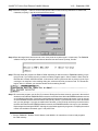
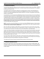
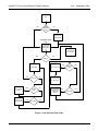
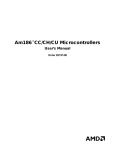
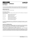
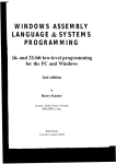
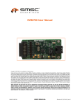
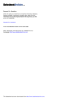
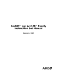
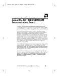
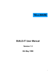
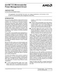
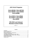
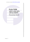
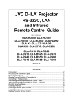
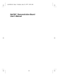
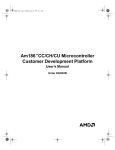
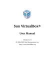
Am186™CC Microcontroller
Voice Over Ethernet
CodeKit Software
Embedded Processor Division
V1.0 – September 03, 1999
Readme File: Version 1.0 – September 03, 1999
1 Overview
This CodeKit software contains a demonstration of voice over Ethernet (VOE) on a local network. Using two
Am186™CC microcontroller customer development platforms (CDPs) or ISDN-to-Ethernet router boards, you can
place voice calls between the two boards over a 10Base-T network using a telephone connected to each board. The
application included enables you to place calls between boards using the Media Access Control (MAC) address of
each board as its phone number.
IMPORTANT: By loading this software or any portion thereof, you agree to all the terms of the License Agreement
in the file LICENSE.PDF. Do not use this software until you have carefully read and agreed to the terms and conditions
in the Agreement. If you do not agree to the terms of the Agreement, do not use this software or any portion thereof.
For support: e-mail
or call
[email protected]
1-800-222-9323
1.1 Tool and System Requirements
The following target hardware and tools are required to build and execute this CodeKit software.
DESCRIPTION
ITEM
Target Hardware
Am186CC microcontroller customer development platform (CDP), version
2.0 or 2.1 and the daughter module, version 2.1
Note that this demo can also be run on a revision 2.1 Am186CC microcontroller ISDN-to-Ethernet router reference design board.
Monitor
AMD E86MON™ software, version 3.3.2 (or newer)
Workstation Operating System
DOS 6.2, or Windows® 3.1, 95, 98, or NT
Tool Suite
Microsoft® Visual C++ V1.52
Compiler*
Microsoft C/C++ optimizing compiler, version 8.00c
Assembler**
Microsoft MASM compatibility driver, version 6.11
Linker*
Microsoft segmented executable linker, version 5.60.339 Dec 5 1994
* Note the compiler and linker are part of the Visual C++ V1.52 tool suite.
** Note MASM6.11 is a separate product and is available with the Microsoft Developer Network on Disk 5 of the
Office Test Platform and Development Tools Pack.
1.2 Installing the CodeKit Software
This CodeKit software is delivered as a self-extracting executable file. Double-click on the EXE file to create a directory
called C:\AMD\CK003000. The CK003000 directory contains the entire contents of the VOE CodeKit.
Page 1 of 13
Am186™CC Voice Over Ethernet CodeKit Software
V1.0 – September 1999
1.3 Files and Directories
The EXE file contains the following files in a single directory.
FILE
DESCRIPTION
186INIT.H
This file contains structure and function declarations for communication
between the 186-specific initialization routines.
AM186CC.H
Common Am186CC microcontroller register masks and definitions.
AMDRIVE.H
Driver definitions for the PCnet-ISA™ II controller.
AUDIO.C
Contains sound recording and playback routines for POTS and HDLC.
BUILDIT.BAT
A batch file that builds CodeKit software.
CLEANIT.BAT
A batch file that cleans up intermediate files after a build.
ENVIRON.BAT
A batch file that sets up the build environment.
HDLC.C
HDLC setup code.
LICENSE.PDF
Licensing agreement for the software contained in the CodeKit.
MAIN.C
Contains simple voice over Ethernet (VOE) demo.
MAKEHEX.EXE
An executable file that converts an EXE program into a HEX file for downloading into the target board using the E86MON software.
PCN.H
Various structures for use in PCnet-PCI™ device driver.
PCNDRV.C
Driver for PCnet-ISA II controller.
PCNDRV.H
PCnet-PCI device driver structures.
PNPAPPN.C
Plug and Play initialization functions for the PCnet-ISA controller.
PNPAPPN.H
Prototypes for functions in PNPAPPN.C.
POTS.C
Drivers for POTS related functions.
POTS.H
Definitions used in POTS.C.
README.FM
This document in Adobe Framemaker format.
README.PDF
This document in Adobe Acrobat PDF.
REG.C
Functions for accessing PCnet-ISA II registers.
SDMAHDLC.C
SmartDMA™ controller HDLC drivers (circular buffer).
STDINCS.H
A header file with standard typedefs and structures.
VOE.EXE
Executable version of VOE software (must be converted to a HEX file).
VOE.HEX
HEX version of VOE software (this gets loaded on your board).
Page 2 of 13
Am186™CC Voice Over Ethernet CodeKit Software
V1.0 – September 1999
1.4 Setting Up the Build Environment
Before the CodeKit software is built, you must set up the build environment. To do this, run the ENVIRON. BAT
command file. Running the command file sets up the environment variables listed in the table below.
This batch file assumes that the tools have been installed in their default locations on the C: drive.
ENV VARIABLE
SETTING
TOOLROOTDIR
C:\MSVC
INCLUDE
C:\MSVC\INCLUDE
LIB
C:\MSVC\LIB
1.5 Setting Up the Target Hardware
This section describes how to set up the target hardware using either an Am186CC microcontroller CDP and daughter
module or an Am186CC microcontroller ISDN-to-Ethernet router reference design board.
1.5.1 General Setup
You need to connect a touch tone phone to the POTS 1 connection on either the CDP daughter module or router
board. You also need to connect an RJ-45 cable, for the Ethernet connector on your board, to a 10Base-T network
or hub.
1.5.2 Revision 2.0 or 2.1 CDP and Revision 2.1 Daughter Module
• DIP switch bank SW12: Ensure DIP switch 4 is on.
• DIP switch bank SW10: All DIP switches should be off.
• DIP switch bank SW8: All DIP switches should be off.
• DIP switch bank SW9: Ensure DIP switch 4 (HDLC_D EN) is set to disabled.
This software requires that HDLC D from the Am186CC microcontroller must be able to transmit directly to the
Am79C031 DSLAC™ device on the daughter module. To do this, populate/depopulate the following resistors on the
bottom of the daughter module. For this CodeKit, use the HDLC D column settings listed in the table below:
Reference
Enabled (HDLC D)
Factory Default
Value
R76
Populate
Depopulate
0
R77
Populate
Populate
10K Ω
R78
Populate
Depopulate
0
R79
Populate
Depopulate
0
R80
Populate
Depopulate
0
R81
Populate
Depopulate
10K Ω
R82
Populate
Depopulate
0
R83
Populate
Populate
10 KΩ
R84
Depopulate
Depopulate
0
R85
Populate
Populate
0
R86
Populate
Populate
10K Ω
Page 3 of 13
Am186™CC Voice Over Ethernet CodeKit Software
V1.0 – September 1999
1.5.3 Revision 2.1 ISDN-to-Ethernet Router Reference Board
To set up a revision 2.1 router board, move the 0-Ω resistor located at R170 to R169. This routes HDLC channel D
directly from the Am186CC microcontroller to the Am79C031 DSLAC device.
1.6 Building the CodeKit Software
Building this CodeKit software is simple:
1. Execute the ENVIRON.BAT file to set up your environment.
2. Execute the BUILDIT.BAT file.
This builds the VOE.HEX file. This file can then be downloaded to the target hardware.
NOTE: The MAKEHEX.EXE utility converts an EXE file into a HEX file. The version of MAKEHEX.EXE you have is
matched to a version of E86MON software. If you have problems loading your HEX file using the E86MON software
on the target board, please contact our support team for a correct version of the E86MON software. Note that the
support team will need to know which version of E86MON software is loaded on your board.
For help with MAKEHEX.EXE, run MAKEHEX with no arguments.
1.7 Loading the Code
You need some kind of terminal program like HyperTerminal (on Windows 95 or NT) or Terminal (on Windows 3.1).
The following steps show you how to connect to an Am186CC microcontroller board using COM1 on your PC with
HyperTerminal (note that the following screen shots are based on E86MON software running on the Am186CC
microcontroller CDP).
Step 1.Connect a null modem cable from COM1 of your PC to either of the serial ports on your board.
Step 2.Run HyperTerminal and create a new connection directly to COM1.
Page 4 of 13
Am186™CC Voice Over Ethernet CodeKit Software
V1.0 – September 1999
Step 3.Click the Configure... button to set the baud rate and other communications parameters to 19200 baud,
8 data bits, no parity, 1 stop bit, and Xon/Xoff flow control.
Step 4.Reset the target board, wait a second or two, then press the a (either upper- or lowercase). The E86MON
software running on the target board detects the baud rate and issues a prompt, like this:
Step 5.This step loads the program into RAM or ROM, depending on which version of E86MON software you are
trying to load. If you reset the board, you have to load the program again1. Select Transfer->Send Text File.
Note that this is a basic ASCII file transfer. In other words, the file is sent as is with no protocol, just as if you
could type it in really fast. In the resulting dialog box, select the HEX file you want to load. The file transfer
begins. After it is finished, your terminal window looks something like this:
Step 6.To execute the program, use the Go (G) command. During the first three seconds, type an a in the terminal
window to ensure that the E86MON software uses the correct baud rate. When the E86MON software receives
an a, it adjusts its baud rate (if necessary) and displays the welcome message and prompt. If you do not type
an a, the E86MON software assumes a baud rate (usually 19200). If your terminal is set to some other baud
rate, you see garbage. If you type an a within three seconds, or are just lucky and have your terminal set to
the same baud rate that the E86MON software assumes, the E86MON software now runs on your hardware.
Depressing and releasing the RESET switch gives you another opportunity to type an a. To display the version
number and available commands, type ? and press Enter.
1. See the E86MON™ Software User’s Manual, order #21891, for instructions on how to load programs
into Flash memory.
Page 5 of 13
Am186™CC Voice Over Ethernet CodeKit Software
V1.0 – September 1999
2 About the Software
The demonstration application enables a voice call to be placed from one board to another over a 10Base-T Ethernet
connection. Calls placed between boards must be on the same network because this application is not capable of
sending packets through routers.
The application begins by attempting to initialize the PCnet-ISA II Ethernet controller. During initialization, the
application checks to see if you have a programmed serial EEPROM connected to your PCnet-ISA II Ethernet
controller. The programmed EEPROM contains the MAC address for your board. The application treats the MAC
address as a phone number.
If your board does not contain a programmed EEPROM, the software manually initializes your PCnet-ISA II Ethernet
controller, then asks you to enter your 12-digit MAC address, which is used as your phone number (program status
is dumped through the serial port to your terminal program). The MAC addresses are in hexadecimal, so this poses
a problem with touch tone phones that just have digits 0-9. To enter an A,B,C,D,E, or F, press “9”, then press the
star (*) key and the 9 becomes an “A”; press the star key again and the A becomes a “B” and so on. When you have
the digit you want, continue to enter the rest of your address, using the same procedure for any other alphabetic
hexadecimal digits you encounter. You must press the “#” key when you are finished. Note that this same method
is used for dialing when placing phone calls.
NOTE: If you want to program the EEPROM on your board, Use the Serial EEPROM Programmer CodeKit software,
CK001101.EXE. You can download this software from the CodeKit Software section under Development Support
and Tools at http://www.amd.com/products/lpd/lpd.html.
When the software has identified your MAC address, you will hear a dial tone if you still have the receiver off the
hook. If you do not hear a dial tone then refer to “Trouble Shooting” on page 12. At this point you are ready to place
a call. Note that you must have a second board set up on the network with a unique MAC address.
To place a call, hang up the phone on the board you want to call. Use the phone on the first board to dial the MAC
address of the board you want to call. Remember to press the “#” key to actually place the call after you dial the
MAC address number. The phone on the second board will start ringing. After the phone is answered by someone
picking it up (takes the phone off the hook), a VOE link is established, and the call proceeds until one of the parties
hangs up (places the phone on the hook).
If you call a board on which the phone is off the hook, you hear a busy signal, indicating that the second party is
either placing a call or has a call in progress. During a call, if either party receives a call request from a third party,
the board receiving the call request transmits a busy packet to the third party.
The software does not have a terminate command unless you add one to the code yourself.
3 How the Software Works
Although this software doesn’t include all of the features of a real Voice over IP system, the VOE software is still
somewhat confusing. The call process is described by the flow chart beginning on page 7. The protocol used does
not follow any standard; the protocol was created solely for demonstrating the voice over Ethernet capabilities of this
CodeKit software.
Page 6 of 13
Am186™CC Voice Over Ethernet CodeKit Software
V1.0 – September 1999
Start
YES
NO
Serial
EEPROM
found?
Manually enter
MAC address
Start Main Program
Loop
Turn on dial tone
and start main
program loop.
Connect flag is
off.
See flow chart
on next page.
NO
YES
Dialing?
YES
Collect digit
YES
Set connect flag
YES
Send out call
request packet
YES
NO
NO
Hung up?
Send out busy
packet
Received a
reply?
Incoming
call?
See flow chart
on next page.
NO
Send terminate
call packet (stop
ringing their
phone)
NO
YES
Hung Up?
NO
Done dialing?
Figure 1: Call Process Flow Chart
Page 7 of 13
Am186™CC Voice Over Ethernet CodeKit Software
V1.0 – September 1999
Received
Ethernet packet
Terminate call
and go to Start
Main Program
Loop on
previous page
YES
YES
Send busy
packet to
requesting
party.
YES
Is there a call
already
active?
Call request
packet?
NO
NO
Play audio data
through our
phone.
NO
YES
Start ringing our
phone
Return to Start
Main Program
Loop on
previous page.
Stop ringing the
phone.
YES
Send out call
reply packet and
set program
state to
connect.
Send out call
terminate
packet and
reset connect
state flag (no
call in progress
now)
Call
terminate
packet?
YES
Have we
hung up yet?
Have we
picked up the
phone?
Stop ringing
phone
NO
YES
Call
terminate
packet
received?
NO
NO
Return to Start
Main Program
Loop on
previous page.
Figure 1: Call Process Flow Chart, Continued
Page 8 of 13
An audio
packet?
NO
Am186™CC Voice Over Ethernet CodeKit Software
V1.0 – September 1999
3.1 How the Audio Portion Works
To provide a fluid, not choppy, sound for the two parties on the phone, this software uses a method that simultaneously
records and plays back sound through a touch tone phone. To accomplish this, HDLC channel D is routed directly
to the AM79C031 DSLAC device, which establishes a data link to the Am186CC microcontroller on which the digitized
audio data travels. Separate transmit and receive paths enable you to perform simultaneous transmit and receive
functions. Because an HDLC channel is used on the Am186CC microcontroller, a SmartDMA controller can be used
to transmit and receive data to and from the DSLAC device with little CPU intervention.
Circular transmit and receive buffers are set up for HDLC channel D. The descriptors pointing to these buffers enable
the buffers to continuously transmit and receive without CPU intervention. When a call is active, HDLC channel D
is continuously transmitting and receiving data at 8000 KHz (the speed of the frame sync clock supplied to the
Am186CC microcontroller and Am79C031 DSLAC device).
The software reads data from the receive buffer shortly after the buffer is written to by the SmartDMA controller.
Then the software writes to the correct location in the transmit buffer shortly before the SmartDMA controller transmits
the data. This is depicted in Figure 2.
Bottom of SmartDMA
controller TX buffer
Bottom of SmartDMA
controller RX buffer
SmartDMA controller
reading here
Software starts writing
ahead of SmartDMA
controller TX
Software reads RX data
behind SmartDMA
controller RX Pointer
SmartDMA controller
currently writing here
Figure 2: SmartDMA Controller Circular Buffers
The software must keep writing just ahead of where the SmartDMA controller is reading so the transmit buffer
transmits HDLC data to the DSLAC device. If this is done correctly, the SmartDMA controller transmits a continuous
flow of audio data without transmitting any stale data, thus preventing a choppy sound quality or an echo.
The software collects sound data for the receive buffer. The sound data is transmitted over 10Base-T Ethernet to
the other board for playback. The software must read data collected by the SmartDMA controller shortly after it has
written the data to the SmartDMA controller buffer. When enough data has been collected it is placed in a TCP/IP
packet and transmitted over a network (the packet is in a TCP/IP format but a TCP/IP stack is NOT used!). For good
sound quality, software must read data that is behind where the SmartDMA controller is writing; otherwise, the
software gets ahead of the SmartDMA controller in the circular buffer and begins reading stale data.
Page 9 of 13
Am186™CC Voice Over Ethernet CodeKit Software
V1.0 – September 1999
3.2 Synchronization
When a call is established, a continuous flow of data must be maintained between the two boards to ensure good
sound quality. Sound is collected at a rate of 8000 KHz, which is relatively slow compared to the 10 Mbit/s transmit
rate of the PCnet-ISA II controller. When a call is active, each board waits for two packets of audio data to be recorded
before sending an audio packet to the other board. While the boards are waiting, they should be playing back data
from a previously received audio packet.
Small packets of 128 bytes of audio data are transmitted between boards in this demonstration. Because data is
collected at 8000 KHz, it takes 16 ms to record enough sound data to be placed in a packet. One caveat is that the
software buffers two packets of data before transmitting them to your ear piece. This means that, while ignoring
Ethernet controller delay time, it takes up to 32 ms for the person on the other phone to hear what you say from your
phone. The human ear barely detects this delay, but 32 ms is a long time to the CPU and PCnet ISA-II controller.
This is why there are few DMA conflicts between the devices; each device has plenty of time to share memory. As
long as there is a continuous cycle of transmitting and receiving packets with a delay close to 16 ms between each
packet received and transmitted, the software maintains a stable voice call.
If there is a lot of Ethernet controller traffic delaying packets, the SmartDMA controller transmit pointer might move
ahead of where the software is writing. This would result in the software transmitting stale data. If this occurs, the
software restarts the SmartDMA controller with the next audio packet received. The software restarts the SmartDMA
controller every time there is a long delay in packets received or if you unplug the Ethernet cable from your board,
then plug it back in (the call is not be lost if you do this).
This Codekit software transmits an audio packet close to every 16 ms unless you have a network with very heavy
traffic. The portion of code that controls transmitting audio data is very robust and does not transmit stale data unless
you manually change the code to include a significant delay of over 32 ms (remember, the software buffers two
packets) somewhere such as a long printf.
NOTE: The numbers in this section might change if you modify the number of bytes that can be transmitted in each
packet. The numbers also might change if you modify the rate of the frame sync or any of the data clocks
corresponding to the HDLC going to the Am186CC microcontroller or the Am79C031 DSLAC device.
3.3 Important Functions
• MAIN() in MAIN.C
This function implements the call setup and termination system that allows you to dial up other boards. This system
is shown in the flow chart beginning on page 7.
• PCNOUTPUT() in PCNDRV.C
This function is used to transmit audio data over a 10Base-T Ethernet connection. The software passes in the length
of the packet, a pointer to the packet that contains an Ethernet/TCP/IP header, and a buffer containing the audio
data. If you want to change the data being passed, refer to section 3.4 on page 11.
• PCNRPROCESS() in PCNDRV.C
The software calls this function to check for new Ethernet packets. This function must be polled often to make sure
data is received as soon as it is available.
• SMARTDMATX() in SDMAHDLC.C
This function inserts audio data into the SmartDMA controller transmit buffer, which transmits the data over HDLC
channel D to the Am79C031DSLAC device. The data is then converted to the analog sound that you hear.
Page 10 of 13
Am186™CC Voice Over Ethernet CodeKit Software
V1.0 – September 1999
This function writes data into the SmartDMA controller transmit circular buffer ahead of the location from which the
SmartDMA controller is reading. This ensures all of the audio data is played back, and that no stale data is transmitted
from the buffer. This function contains the code that keeps the call between two boards synchronized to prevent too
much echo and the transmission of stale data.
• SMARTDMARX() in SDMAHDLC.C
This function should be polled frequently to detect when the SmartDMA controller receive buffer collects enough
HDLC channel D data from the Am79C031DSLAC device to be placed into an Ethernet packet. This packet is then
transmitted to another board. The audio data is placed into a buffer passed to this function. If this function is not
polled frequently enough, packets might not be transmitted at the 16-ms rate required to achieve a good quality voice
call.
3.4 Tweaking the Code
The size of the audio packets sent between boards is one of the biggest factors affecting sound quality in this
application. This application uses a packet size of 128 bytes. This packet size minimizes echo and allows a latency
of up to 16 ms on a network. This enables the packet to get to its destination before sound quality is compromised.
The smaller the packet sent, the less echo the listener will hear because there is a shorter delay between when the
caller says something and when the person on the other end of the line hears it.
The reason echo occurs is that the Am79C031 DSLAC device is programmed to cancel out echo by guessing what
sort of echo will come back from the end of the call you place. The DSLAC device then subtracts the equivalent of
that echo to cancel it out. If there is a lot of latency in the line, the DSLAC device subtracts the echo at the wrong
time and the listener hears the echo. The echo can be twice as bad with the DSLAC device trying to compensate in
this particular case. Effectively, the less delay between when you say something and when the listener hears it, the
better the DSLAC device’s echo cancellation feature works.
One drawback to using small audio packets is the overhead associated with each Ethernet packet transmitted and
received. If you make packets too small, the PCnet-ISA II controller spends its time processing Ethernet headers
and possibly struggling with the Am186CC microcontroller over memory cycles to access memory. This compromises
sound quality because the code has less time to manage the SmartDMA controller.
If echo is acceptable in your application, then you could use larger packet sizes. When using larger packet sizes,
the software is more tolerant of Ethernet traffic. Larger packets hold more audio data, resulting in a longer acceptable
delay between packet transmission and receipt before synchronization between both ends of the call is lost. Also
remember that larger packets result in more time between when the caller says something and when the listener
hears it.
To change the size of the audio portion of the packets transmitted and received, change the value of MAX_DATA,
which is defined in MAIN.C. Note that MAX_DATA must be evenly divisible into the sizes of the TX_BUFSIZE and
RX_BUFSIZE definitions in SDMAHDLC.C. Those two definitions are the sizes of the SmartDMA controller’s transmit
and receive circular buffers. If MAX_DATA is not evenly divisible into those sizes, the transmit and receive circular
buffers wrap, and you will hear a continuous clicking sound while a call is in progress.
The SmartDMA controller transmit and receive buffers are effectively split into blocks the size MAX_DATA. If
MAX_DATA is not evenly divisible into those block sizes when the SmartDMA controller buffers wrap, data written
into or read from the buffers at that point might be concatenated. This results in a loss of audio data that you transmitted
or received. You can change the size of the TX_BUFSIZE and RX_BUFSIZE definitions located in SDMAHDLC.C,
but make sure that MAX_DATA is evenly divisible into them. The maximum size of the TX_BUFSIZE and
RX_BUFSIZE is 32K.
If you want to edit the code that keeps your audio synchronized, use the SMARTDMATX() function in SDMAHDLC.C.
Page 11 of 13
Am186™CC Voice Over Ethernet CodeKit Software
V1.0 – September 1999
Another important definition in the code is the BUFFER definition, which is defined in SDMAHDLC.C. This controls
how many audio packets your board buffers before transmitting the sound to your phone. BUFFER is currently
defined as two. This means that when someone calls you, the software on your board buffers two audio packets
before sound is transmitted to your ear piece. This results in a 32-ms delay between someone establishing a call
with you and you hearing them.
When sound is buffered, you continue receiving audio packets at a rate of one every 16 ms, but the sound is delayed
by 32 ms because of the packets buffered at the beginning of the call. Making the BUFFER definition less than two
makes it difficult for the software to keep a constant stream of audio data flowing to your phone. A BUFFER definition
of less than two also makes the system more susceptible to network latency. Making the BUFFER value too large
can result in echo or an unreasonable amount of delay between when you say something and when the listener
hears it.
One solution for the problems associated with using small Ethernet packets is to reduce the value of MAX_DATA
and increase the value of BUFFER. This causes multiple packets to be buffered at the beginning of the call, making
the system more tolerant of network latency.
NOTE: This application does not use a TCP/IP stack. You will have to merge this code into your stack if you want
to place calls from one network to another.
4 Trouble Shooting
This section describes some problems you might encounter while using this CodeKit software and offers some
possible solutions.
I started the software, but the status information didn’t appear on my screen.
This is probably a result of your board’s baudrate not matching that of your terminal. Reset your CDP or router board
and type an a within three seconds of reset to help the E86MON software autobaud.
If you do not type an a, make sure that the cpuspeed, baudrate, uart, and autorun permanent variables are set
correctly.
When I pick up the phone, I don’t hear a dial tone.
Be sure to check your hardware setup and make sure that the phone is plugged into the POTS 1 connection on your
CDP or router board. If your board’s Ethernet EEPROM is not programmed, you must type in your MAC address
using your phone’s touch tone keys before you can hear a dial tone.
When I dialed another board’s MAC address, the board’s phone didn’t ring.
Make sure that you dialed the correct MAC address and that the board you are calling has a valid MAC address.
The phone on the other end of the line must be hung up (on the hook), and the board that the phone is connected
to must be on the same network you are calling from. No routers can be located between the boards on the network.
Two MAC addresses that work are 22 33 44 55 66 77 and 22 33 44 55 66 78.
Page 12 of 13
Am186™CC Voice Over Ethernet CodeKit Software
V1.0 – September 1999
I hear lots of clicking sounds during a call.
This could be due to any of the following:
•
You have a very poor Ethernet link.
• There is a large amount of traffic on the network to which you are connected.
• You set the value of MAX_DATA too low in MAIN.C.
• You set MAX_DATA to a value that is not evenly divisible in the sizes of the TX_BUFSIZE and RX_BUFSIZE
definitions in SDMAHDLC.C.
Note that even when the system is running smoothly, you will occasionally hear line noise.
I hear lots of echo.
It is likely that you will hear some echo or reverberation during calls. If there is a lot of echo, you may have changed
MAX_DATA or BUFFER (in SDMAHDLC.C) to values that are too large. Refer to section 3.4 on page 11 where these
values are discussed.
It sounds like I’m in a metal cage, and someone is pounding it with a hammer.
If you’re using a router reference design board, make sure that you are using at least revision 2.1. If you are using
a CDP with a daughter module, the daughter module must be revision 2.1.
NOTE: Daughter modules that are revision 2.0 and below do not run this software properly.
Trademarks
© 1999 Advanced Micro Devices, Inc. All rights reserved.
AMD, the AMD logo, combinations thereof, Am186, DSLAC, E86MON, PCnet-ISA II, PCnet-PCI, and SmartDMA are trademarks
of Advanced Micro Devices, Inc.
Microsoft and Windows are registered trademarks of Microsoft Corporation.
Other product names used in this publication are for identification purposes only and may be trademarks of their respective
companies.
Page 13 of 13