1
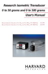
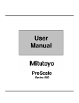
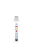
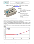
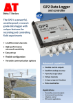
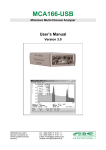
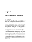
CSP10 … 13 Charge Sensitive Preamplifier User Manual Copyright FAST ComTec GmbH Grünwalder Weg 28a, D-82041 Oberhaching Germany Version 1.0, September 17, 2009 Warranty Warranty Equipment manufactured by FAST ComTec GmbH is warranteed against defects in materials and workmanship for a period of twelve months from date of shipment, provided that the equipment has been used in a proper manner as detailed in the instructions manuals. During the warranty period, repairs or replacement will be made at FAST ComTec’s option on a return to factory basis. The transportation cost, including insurance to FAST ComTec is the responsibility of the Costumer except for defects discovered within 30 days after receipt of equipment where shipping expense will be paid by FAST ComTec. Copyright © 1988 - 2009 FAST ComTec GmbH D-82041 Oberhaching, Germany All rights reserved This manual contains proprietary information; no part of it may be reproduced by any means without prior written permission of FAST ComTec, Grünwalder Weg 28a, D-82041 Oberhaching, Germany. Tel: ++49 89 6651800, FAX: ++49 89 66518040. The information in this manual describes the hardware and the software as accurately as possible, but is subject to change without notice. ComTec GmbH II Table of Contents Table of Contents 1. Introduction ............................................................................................................................. 1-1 2. Specifications .......................................................................................................................... 2-1 2.1. Inputs.......................................................................................................................... 2-1 2.2. Outputs....................................................................................................................... 2-1 2.3. Performance............................................................................................................... 2-1 2.4. Connector Types and Cables..................................................................................... 2-1 2.5. Power ......................................................................................................................... 2-1 2.6. Physicals .................................................................................................................... 2-2 3. Controls and Connectors ........................................................................................................ 3-1 3.1. General....................................................................................................................... 3-1 3.2. Front Panel / Rear Panel............................................................................................ 3-1 4. Installation ............................................................................................................................... 4-1 4.1. Noise Consideration ................................................................................................... 4-1 4.2. Detector Bias.............................................................................................................. 4-1 5. Operating Instructions ............................................................................................................. 5-1 5.1. General....................................................................................................................... 5-1 5.2. Test Input ................................................................................................................... 5-1 5.3. Initial Setup................................................................................................................. 5-1 5.4. Initial Checkout........................................................................................................... 5-1 5.5. Common Operating Problems.................................................................................... 5-1 6. Theory of Operation ................................................................................................................ 6-1 6.1. Functional Description................................................................................................ 6-1 6.2. Detailed Circuit Description ........................................................................................ 6-1 7. Appendix ................................................................................................................................. 7-1 7.1. Detailed Schematic of the CSP10…13 ...................................................................... 7-1 7.2. Personal Notes........................................................................................................... 7-2 ComTec GmbH III WARNINGS WARNINGS The input of the CSP1X is very sensitive. Never connect the detector when the high voltage is applied. Increase or decrease the high voltage only at a very slow rate. Observe the output of the CSP1X during bias voltage change with an oscilloscope. Do not allow the output to saturate during change of high voltage. ComTec GmbH IV Introduction 1. Introduction FAST ComTec’s CSP10...13 is a single channel charge sensitive preamplifier module intended for use with various types of radiation detectors including semiconductor detectors (e.g. Si, CdTe and CZT), P-I-N photodiodes, avalanche photodiodes (APDs), and various gas-based detectors. The CSP10...13 is one of a series of four charge sensitive preamplifiers offered by FAST ComTec, which differ from each other most notably by their gain. A guide to selecting the best charge sensitive preamplifier for your application can be found on the next page or at our web site: http://www.fastcomtec.com. As with all FAST ComTec’s preamplifier modules, the CSP10...13 is housed in a small shielded metal case with a D-sub 9 connector for power supply. The FAST ComTec Model CSP10...13 Charge Sensitive Preamplifier is designed for optimum performance with Silicon Surface Barrier (SSB) detectors. Operating as a charge to voltage converter, the unit accepts charge carriers produced in the detector during each absorbed nuclear event. The output then provides a voltage in direct proportion to the collected charge at the rate of 1.4V per picocoulomb. This translates to a gain of 62mV per MeV (see table) for room temperature silicon detectors. For typical use with positively biased SSB detectors, the extremely linear energy output provides a negative polarity pulse ideal for energy spectroscopy. The high charge rate capability of the design is evidenced by an energy rate capacity of greater 5 than 10 MeV per second when used with silicon detectors. In order to take full advantage of such a high count rate capabilty, a main amplifier with a correspondingly high count rate ability, such as the FAST ComTec Model CSA4, should be used. The basic operation of the preamplifier is indicated in the functional schematic diagram below. The first stage acts as an operational integrator which produces an output potential proportional to the accumulated charge on the feedback capacitor Cf. The integrator drives the output buffer with a gain of +2. The noise contribution of the preamplifier is only 1.7 KeV, FWHM, (Si) with an increase of less than 34 eV for each picofarad of additional source capacitance. To reduce noise injected through the HV input, a decoupling network is utilized for filtering the detector bias voltage. To reduce the possibility of transmission line reflections when using long lengths of coaxial cable, the energy output is provided with a series resistor, eliminating the necessity of terminating the line at the receiving end. For those applications utilizing lower voltage detectors with vacuum chamber feedthrough connectors or direct detector cabling inside a chamber, the Model CSP10...13-1B provides a BNC for the detector and HV bias input. Necessary power is provided by any FAST ComTec main amplifier through the five foot compatible cable furnished with the preamp. Tables to the CSP10...13 ComTec GmbH 1-1 Introduction ComTec GmbH 1-2 Specifications 2. Specifications 2.1. Inputs @ 20ºC, ±12V, unloaded output Preamplification channels: 1 up to ± 4000 volts (SHV) Test input 50 ohms terminated for tail pulser 2.2. Outputs Decay time constant: 140 µs (150 µs, 50 µs, 50 µs resp.) Unsaturated output swing: -3 to +3 volts Output offset: +0.2 to -0.2 volts Output impedance: 50 ohms 2.3. Performance Equivalent noise charge (ENC)*: ENC RMS: 200 electrons, 0.03 femtoCoul. Equivalent noise in silicon: 1.7 keV (FWHM) Equivalent noise in CdZnTe: 2.4 keV (FWHM) ENC slope: 4 electrons RMS /pF Gain: see table 1 Rise time**: 7 ns (see table 1) Maximum charge detectable per event: (see table 1) Operating temperature: -40 to +85ºC 2.4. Connector Types and Cables Power: D-sub 9 HV Input: SHV (BNC for CSP1x-1B) Detector Input: SHV for the models CSP1x-xS BNC for the models CSP1x-1B / CSP1x-1BS Output: BNC Cable: A five foot power cable with required connectors is supplied with the preamplifier. 2.5. Power Power supply voltage (Vs): ± 12 volts nominal (± 2 volts) ComTec GmbH 2-1 Specifications Power supply current: < 10 mA Power dissipation: < 240 mW 2.6. Physicals Net weight: 250 gr. Size without connectors: 126 mm x 80 mm x 30 mm Size with connectors: 165 mm x 80 mm x 30 mm • Measured with input unconnected, using Gaussian shaping amplifier with time constant =1 s. With a detector attached to the input, noise from the detector capacitance, leakage current, and dielectric losses will add to this figure. ** Pulse rise time (defined as the time to attain 90% of maximum value) has a linear relationship with input capacitance. Value cited in the table assumes zero added input capacitance. Tocalculate pulse rise time for practical situations, use the equation: tr =0.4 Cd + 7 ns, where tr is the pulse rise time in ns, and Cd is the added capacitance (e.g. detector capacitance) in pF. Keep in mind that other factors within the detection system may further limit this value. ComTec GmbH 2-2 Controls and Connectors 3. Controls and Connectors 3.1. General This section describes the functions of the controls and connectors located on the front and rear panels of the Model CSP10...13. It is recommended that this section be read bevor proceeding with the operation of the preamplifier. 3.2. Front Panel / Rear Panel Input ComTec GmbH Test input Output Power Supply HV in 3-1 Installation 4. Installation 4.1. Noise Consideration The preamplifier components associated with the detector bias (HV) have been scientifically cleaned. This process removes all residues and fingerprints which could cause excessive noise and possible failure of the preamplifier when high voltage is applied. It is strongly recommended that causion be exercised never to touch these components nor have them exposed to the atmosphere without the preamplifier case, for any long duration. Any capacitance added to the input of the preamplifier will increase the noise contribution and degrade the rise time performance of the Model CSP10…13. The capacitance should be minimized by using the shortest possible interconnecting cable between the detector and the preamplifier. The detector load resistance R is normally 100 megaohms. If silicon surface barrier detectors are used whose leakage current is greater than 1 microamp, the voltage drop across the resistor must be allowed for, or alternatively, the value of R reduced to provide an voltage drop. The latter will cause the 0 pF noise of the preamplifier to increase, but this will usually be insignificant compared to the noise generated in the detector by the increased leakage current. Do not reduce R below 10 megaohms without contacting the factory. 4.2. Detector Bias The Model CSP1X-4S Preamplifier HV Input accepts up to ± 4000 VDC from the detector bias supply. Never connect or disconnect the preamplifier from a detector while the high voltage is on. Always wait at least one minute after the detector bias has been reduced to zero bevor disconnecting the preamplifier from the detector. Maximum stability of the preamplifier is maintained 60-90 seconds after preamplifier power and high voltage is applied. The Model CSP1X-2S has a larger input coupling capacitor (10 nF) for detectors with high capacity . If the maximum detector bias is below 1000V, the Model CSP1X-1B is the right choice. The input connector and the HV bias connector is BNC. It is usually more convenient to use BNC, because these connectors are much more common. For Vacuum applications, the feed through connector is in many cases only available as BNC. ComTec GmbH 4-1 Operating Instructions 5. Operating Instructions 5.1. General The purpose of this section is to familiarize the user with the Model CSP10...13 Preamplifier and to check that the unit is operating correctly. Since it is difficult to determine the exact system configuration in which the unit will be used, explicit operating instructions cannot be given. However, if the following procedure is carried out the user will gain sufficient familiarity with the instrument to permit its proper use in the system at hand. The instructions which follow may be best carried out with the preamplifier on latest bench, seperated from the detector. Because the input is charge sensitive, and ultra high impedances are involved, the Preamplifier is inherently somewhat microphonic. For best results, testing should be done with the Preamplifier chassis cushioned on a block of foam rubber, and the cover securely fastened to the frame. 5.2. Test Input The Model CSP10...13 accommodate a TEST input via a BNC connector on the front panel introduces the externally applied signal (preferably a negative tail pulse of -1 to -5 volt peak amplitude) to a charge injection capacitor to the summing junction of the inegrator. The test signal voltage is usually adjusted in amplitude by the user so as to give a reference peak signal in his data spectrum at a convinient location so as to normalize multiple detectors. This input does provide a resistive terminating impedance. 5.3. Initial Setup 1. Connect the Preamp to a source of low voltage power such as a FAST ComTec Spectroscopy Amplifier using the five foot cable provided. 2. Using the RG-58C/U coax, connect the Preamp output to channel 1 of a dual trace Oscilloscope. 3. Connect the negative, attenuated output of a tail pulse generator (such as the Berkeley Nucleonics Corp.: BH-1, PB-5 Tail Pulser) to channel 2 using RG-58C/U and a „tee“ at the Scope input. 4. The other other side of the „tee“ should be connected to the Test input BNC connector through a length of RG-58C/U coax. 5. Select Scope vertical sensitivities of 50 mV/div. And set the time base to 10 µs/div. Turn Preamp power on. 5.4. Initial Checkout Using the Test input BNC provided on the Model CSP10(...13), a detector input of approximately 100 MeV per input volt is simulated. Adjust the Pulser for -20 mV peak input signal and observe a Preamplifier energy output of +130 mV peak (nominal). This is equivalent to a detector input of 2.1 MeV (nominal). 5.5. Common Operating Problems The modern spectrometer is an extremly sensitive, state-of the-art system. Inexact performance of other than the grossest type is generally due to subtle factors. It is the ability to determine and correct these factors that constitutes the art in the science of spectroscopy instrumentation. ComTec GmbH 5-1 Operating Instructions All of the many possible contributors to less than optimum performance cannot be listed here. The purpose of this section is to note the usual causes of loss of resolution, and to suggest curative steps. Do not expect to diagnose all problems with the detector, a preamplifier, a main amplifier, and a multichannel analyzer. The spectroscopy system records results, it does not necessarily lead to the identification of causes. A good, modern oscilloscope will be needed. Also a high quality tail pulse generator will be extremely useful. The simplest test is, of course, to connect your detector, apply bias, present a source, and accumulate a spectrum. Be sure a pulser is not feeding the preamplifier while the spectrum is accumulting, or resolution loss may result. If the results obtained are far different from what is expected, it than becomes necessary to troubleshoot the system. First observe the amplifier output on an oscilloscope at various time base and amplitude settings. Is the amplifier properly pole/zero cancelled (do the output pulses cause undershoot that persist for longer than two or more main pulse widths)? Set the main amplifier pole/zero cancellation (without DC resolution) to obtain the most rapid, complete baseline recovery. The next step is to remove all sources and, with the detector still connected and bias applied, present a test pulse to the detector input of the preamplifier using the test input described in Section 5-2. Make sure the pulser polarity is correct. Set the amplitude of the pulser so that ist peak accurs near the region of the peak of the source previously used. Observe the output of the amplifier without DC restoration. Note that the amplifier is not properly pole/zero cancelled for the pulser feeding the preamp (due to the extra time constant of the pulser). This is of no consequence for a pure pulser input. Are the baseline fluctuations of 50/60 or 100/120 Hz frequency? A ground loop is indicated. Insert all system line plugs into the same output. Or are the baseline fluctuations of ramdom frequency between 10 Hz and 15,000 Hz? The area may be too noisy, causing microphonic problems. If high frequency noise is observed, is it random or periodic? Periodic noise is a sign of electronics failure; isolate the cause by observing the preamplifier output. Is the same pattern observed, or is the problem in the main amplifier? Random high frequency noise may be detector load resistor or input capacitor breakdown. Next, accumulate a pulser peak on the analyzer. Calculate its resolution. Repeat with the detector removed and the input connector of the preamplifier shielded. (Wait five minutes to remove the preamplifier from the detector after removing the detector bias.) You now have three resolution figures available for essentially equal energy peaks: RS: source RD: pulser and biased detector connected RE: puser without detector connected If RE is not less than 2.0 keV for two microseconds unipolar Gaussian shaping time constant, the problem is in the electronics and probably in the preamplifier. If RE is acceptable, but RD is greater than 2.0 keV plus 10 eV/pF detector and connection capacitance, then the problem is either in the detector (microphonics, excess leakage current noise, breakdown due to moisture or grime on the detector output connectors), or in the preamplifier (leaky input capacitor, dirty or moist detector load resistor, dirty or moist detector input connector). If RE and RD are acceptable, but the live spectrum (RS) is not as good as expected, the problem is probably in the detector (bad detector, poor charge collection, insufficient bias) or in the electronics following the preamplifier (count rate too high, improper amplifier pole/zero cancellation, wrong main amplifier time constant, wrong amplifier shaping-bipolar vs. Unipolar, improper amplifier shaping for the ADC being used, ADC cannot take the count rate, amplifier or ADC drift). These many alternatives are not easy to check. Substituting, one-by-one other detectors, preamplifiers, amplifiers, and multichannel analyzers may help pinpoint the problem. Checking the above common problems will aid in spotting the source of trouble. ComTec GmbH 5-2 Theory of Operation- Detailed Circuit Description 6. Theory of Operation 6.1. Functional Description Charge sensitive preamplifiers are used when radiation is detected as a series of pulses, resulting in brief bursts of current flowing into or out of the preamplifier input. Depending on the type of detector, this burst of current may be very brief (<1 ns) or as long as a few seconds. For an idealized detection current pulse taking the form of a delta function, the detected charge (time integral of the input current) will ideally take the form of a step function. The output waveform of an actual charge sensitive preamplifier will of course have a non-zero rise time: for the CSP10...13 this figure is approximately 7 ns. Furthermore, capacitance at the preamplifier input (i.e. detector capacitance) will further slow the rise time at a rate of 0.4 ns / pF. Keep in mind the output rise time will also be limited by the speed of the detector. For example, the detection current pulse from a CsI(Tl)/photodiode scintillation detector has a duration of approximately a couple s, so the expected rise time of the charge sensitive preamplifier output will be at least that long. The output waveform of the CSP10...13 using a capacitively-coupled fast square wave pulser at the input is shown below to the left. At long time domains, the output decays due to the discharge of the feedback capacitor through the feedback resistor, with an RC time constant of 140 µs. This decay of the output waveform is also shown below, to the right. 6.2. Detailed Circuit Description Figure 2 shows a simplified equivalent circuit diagram of the hybrid amplifier module used in the CSP10...13, which is a two stage amplifier. The first stage is high gain, and the second stage is low gain with an emphasis on supplying sufficient output current to drive a terminated coaxial cable. Rf (100 MΩ) and Cf (1.4 pF) are the feedback resistor and capacitor respectively (tdecay= 140µs). The feedback values for the other models are: Rf =10 MΩ and Cf =15 pF, tdecay= 150 µs (CSP11), Rf =680 kΩ and Cf =75 pF, tdecay= 50 µs (CSP12), Rf =68 kΩ and Cf =750 pF, tdecay= 50 µs (CSP13). The CSP10...13 preamplifier module consists of: • hybrid charge sensitive preamplifier • input DC block capacitor • test input with 50 ohm termination • 1 pF test capacitor ComTec GmbH 6-1 Theory of Operation- Detailed Circuit Description • high voltage path with filter circuit and • power supply circuitry ComTec GmbH 6-2 Appendix- Detailed Schematic of the CSP10(…13) 7. Appendix 7.1. Detailed Schematic of the CSP10(…13) ComTec GmbH 7-1 Appendix- Personal Notes 7.2. Personal Notes ComTec GmbH 7-2