1
_______________________________________________________________________________________________________
BL-3G
_________________________
Ultra stable 3-Axis Gyro
Advanced User Manual
_______________________________________________________________________________________________________
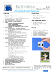
Features
Applications
Small size, weight and power
USB / PC connection for set up and upgrade
Ultra stable over temperature and time
0
0
Operational temperature: -30 C to +85 C
ST L3GD20 MEMs rate sensor
ARM Cortex processor for control and I/O
UART connection for system developers
Filters
o Low pass
o High pass (programmable)
o Kalman (programmable)
o Rolling average (programmable)
o Automatic Gain Control (AGC) option on all axes
Control algorithm
o PID (Proportional, Integrative, Differential)
o All gain parameters programmable (+3 external pots)
Input Tx/Rx matching
o Match up to any RC transmitter
o Allows low cost system with high end features
Curves (input stick curves)
o Many standard and also x4 use programmable
o Good for aircraft control at low cost
Mixing functions / trim
o Flying-wing, V-tail, Flaps, Flaperon aircraft
o Power in and out (for curve transformation)
o Trim and range adjustments for fine tuning
X 3 Rx inputs and X 6 outputs for control signals:
o Pitch
o Roll
o Yaw
X 4 real time programmable inputs for:
o Gyro PID gain low / high set and rate set
o Gyro PID gain modulation based on input
o Gyro on/off
o "Critical time" mode for spin / crash recovery
o "Take off" mode for perfect cross wind take offs
o Mixing of Z axis (yaw) mix gain control
o Power in
o Emergency cut off
o 'Heading lock' gyro function (all axes)
o 2 x Input curves switchable in real time
1 x UART for 16 bit raw X, Y, Z rate and 8 bit
temperature digital data out and PC connection
Highly programmable for many applications
Variable input voltage (20v to 5v, or down to 3.3v)
LED displays to show gyro operational
Factory calibrated
RoHS, “green” compliant
See videos and more details at: www.bluelight-tech.com/BL-3G.htm
RC aircraft Stabilization (Gas / Electric)
Multi-copter / UAV stabilization
General Robotics
Size, power and weight
42 x 38 x 18 mm unit
45 mA when in normal operation
Weight is 19g (0.67 Oz)
PC tool
Intuitive and easy to use software for
detailed user programming
Graphical real time data monitoring
Graphical matching to RC transmitter
Graphical curve generation tool
USB and / or UART connection
This ultra stable BL-3G MEMS based gyro
is ideal for stabilizing all manor or aircraft.
It is specially set up for RC flying
applications.
Bluelight Technologies Co. Ltd. | BL-3GRC, 3 axis gyro User Manual V2.4
1 of 71
Contents
Page
1.0 Introduction and block diagram ............................................................. 4
1.1 Gyro connection PC ...........................................................................
5
1.2 Gyro connection to aircraft .................................................................
6
1.2.1 Avoiding unwanted vibration .................................................. 5
1.3 Gyro electrical installation ................................................................... 7
1.3.1 Typical system connection...................................................... 7
1.3.2 High current system connection ............................................. 9
1.3.3 Typical Multi-copter system connection ................................. 10
1.3.4 Cables and Power .................................................................. 12
2.0 PC tool and Programmable features .....................................................
2.1 Tab Quick Start: Standard aircraft types ............................................
2.1.1 Quick "Out of the box" installation (Fixed wing) .....................
2.2 Tab Basic: Basic operational modifications ........................................
2.2.1 Real-time functions or power bias inputs ...............................
2.2.2 Input Invert .............................................................................
2.2.3 Gain adjustments ...................................................................
2.2.4 Activity LED ............................................................................
2.2.5 Gyro On/Off switch ………………….…………………………..
2.2.6 Outputs …………………………………….…………..…………
2.2.6.1 Throttle Safety Lock ………………………..…………
2.2.7 Outputs - Bias and invert ………..………………………….….
2.2.7.1 Stall softener feature ................................................
2.2.8 Outputs - Aircraft Type ……………………………………….…
2.2.9 Outputs – Output connection …………...………………..……
2.3 Tab Tools: Programming and testing ................................................
2.3.1 Communications ....................................................................
2.3.2 File save and read back options ............................................
2.3.3 Real time data test .................................................................
2.3.4 Temperature ..........................................................................
2.4 Tab Mixing: Control mix and flaps ......................................................
2.4.1 Mix Options …….…………….………………………....…….…
2.4.2 Flap Modes …….…………….………………………....…….…
2.5 Tab Curves: Input Curve set up .........................................................
2.5.1 Set up …….…………….………………………………..…….…
2.5.2 Curve Options …….…………….……..………………..…….…
2.5.2.1 User Curves .............................................................
2.5.3 Test Curve …….…………….……..………………..……..….…
2.6 Tab Advanced 1: Advanced modifications ........................................
2.6.1 RC Tx input matching ...........................................................
2.6.2 Control Surface Trim .............................................................
2.6.3 Control Surface Range ..........................................................
2.6.4 PWM detailed set up .............................................................
2.6.5 Gyro Function Invert .............................................................
2.7 Tab Advanced 2: Advanced modifications ........................................
2.7.1 Temporary Gyro rate and gain targets ("Critical time" mode)
2.7.1.1 "Gyro on" rate and target changes .........................
Bluelight Technologies Co. Ltd. | BL-3GRC, 3 axis gyro User Manual V2.4
13
13
14
16
16
16
16
17
17
17
18
18
18
18
19
20
20
21
21
21
22
22
23
25
25
25
26
27
28
29
30
31
33
33
34
34
34
2 of 71
2.7.1.2 "Take off" rate and target changes .........................
2.7.2 Programmable Real Time inputs ...........................................
2.7.2.1 Gyro on/off................................................................
2.7.2.2 Gyro Two Gain Adjust ..............................................
2.7.2.3 Gyro Exact Gain .......................................................
2.7.2.4 Gyro PID Target .......................................................
2.7.2.5 Z axis mix to X and Y gain adjustment......................
2.7.2.6 Power-in mode .........................................................
2.7.2.7 Emergency cut off ....................................................
2.7.2.8 I adjust (Heading Lock) ............................................
2.7.2.9 Input power and pitch curves ...................................
2.7.2.10 Flaps control input .................................................
2.8 Tab Professional 1: Professional 1 modifications ..............................
2.8.1 Pitch Roll and Yaw axes PID controllers ……………….……
2.8.2 Automatic Gain Control (AGC) ..............................................
2.8.3 Rate data range .…………………………………………..……
2.8.4 Gyro data rate ……………………………………………..……
2.9 Tab Professional 2: Professional 2 modifications ..............................
2.9.1 Kalman filters …….……………………………………..…….…
2.9.1.1 IM (Inertial Mass) ....................................................
2.9.1.2 MN (Measurement Noise) .......................................
2.9.1.3 AN (Acceleration Noise) ..........................................
2.9.2 Predictive mode ………….………………………………..……
2.9.3 High Pass Filter (HPF) …..………………………………..……
2.9.4 Data averaging……………………………………………..……
2.9.5 Fine Zero Calibration ............................................................
2.9.6 Gyro Lock ..............................................................................
2.9.6.1 Normal mode ...........................................................
2.9.6.2 Un-commanded mode .............................................
2.9.6.3 Proportional mode ...................................................
2.10 Tab Info: Set up information display ..................................................
2.11 Tab Live data: Data analysis ...............................................................
2.12 Tab Upgrade: Upgrade firmware .......................................................
2.12.1 BL-3G firmware upgrade......................................................
2.12.2 BL-3G system developer upgrade........................................
2.13 Tab About: Bluelight Technologies ....................................................
35
36
36
36
36
37
37
38
38
38
39
39
40
40
41
41
41
42
42
42
42
43
43
43
44
44
44
44
44
45
46
48
50
51
52
53
3.0 Detailed Specifications ........................................................................... 54
3.1 Functional specification .....................................................................
54
3.2 Hardware specification ......................................................................
56
4.0 System developer additional features ...................................................
4.1 Standard commands ...........................................................................
4.2 ST L3GD20 registers direct access commands ...................................
4.3 Self Test ...............................................................................................
57
57
61
62
5.0 Abbreviations and terms used in this document .................................. 64
6.0 PC Set-up tool installation ....................................................................... 66
Bluelight Technologies Co. Ltd. | BL-3GRC, 3 axis gyro User Manual V2.4
3 of 71
1.0 Introduction and block diagram
The BL-3G gyro has been designed to allow a great deal of fine tuning by the RC
model flyer. Gyro control algorithms cannot be perfectly set up for each and every
model. Amongst other things, the control algorithm operation depends on the gyro
distance relative to the control surfaces, the weight of the model, how much vibration
the model generates, how fast the model is flying, etc. etc. On top of this, each flyer
will generally have different flight characteristics and performance requirements.
Hence the BL-3G comes with a PC set up software that opens up all the important
parameters to allow the RC flyer to set things up exactly as required. There are also
useful curve, mix, trim and special functions. (As detailed later, there are better ways
to trim a gyro equipped aircraft, rather than the normal way with the RC receiver).
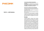
The BL-3G gyro block diagram is show below:
BL-3G
Pitch
RC receiver
Input 1
Programmable
Roll
Programmable
Yaw
Programmable
Programmable
Input 2
Output 1
Output 2
Input 3
Input 4
Output 3
Input 5
Output 4
Input 6
Output 5
Input 7
Output 6
Pitch
Negative Pitch
Roll
Negative Roll
Yaw
Negative Yaw
USB
Rx Tx Gnd
Ground
(black
wires) to
OUTSIDE
of PCB
Input1
.
.
.
.
Input7
UART connection
Output1
.
.
.
.
Output6
Gnd 5v Sig
Ground
(black
wires) to
OUTSIDE
of PCB
Sig 5v Gnd
Potentiometers (pitch, roll, yaw gain adjust)
Bluelight Technologies Co. Ltd. | BL-3GRC, 3 axis gyro User Manual V2.4
4 of 71
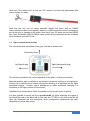
With the LEDs indicating the following:
Red (Power on), blue (Software working), red (PC update / Up-side-down mounting), green
(Gyro on, or angular rate>10 deg/sec when gyro off).
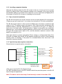
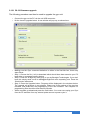
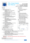
1.1 Gyro connection to PC
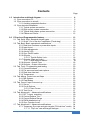
One PC USB-A (male) to mini USB-B (male) cable is supplied:
This allows high speed communications between the PC and the BL-3G gyro. It also
provides power to the gyro. Note that the USB is limited to drawing 100 mA current
from the PC. This is enough to drive the BL-3G gyro and normally also the connected
RC receiver. However an external 5V DC power supply (battery or ESC output)
MUST be connected to the unit if servos are also connected at the same time.
The power can be connected to any input or output (but not the UART pins). Note that
during normal flight the gyro will take power from either a separate battery for petrol
engine aircraft, of from the electric motor controller for electric flyers. It is most
important to make sure the connections are such that the ground wire is always
connected to the outside pin of the BL-3G gyro.
Ground pins (black wire) are ALWAYS on the outside of the PCB.
(5V in the centre and the signal on the inside).
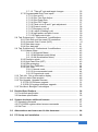
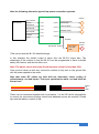
Four gold plated contact Futaba J type 3 pin cables (with polarization tabs) are
supplied with the BL-3GRC unit (not with the BL-3GMod):
These for connecting the RC receiver outputs to the gyro inputs.
Bluelight Technologies Co. Ltd. | BL-3GRC, 3 axis gyro User Manual V2.4
5 of 71
Note that if the cables don't fit into your RC receiver unit then the polarization tabs
can be simply cut away.
Note that the unit can be easily operated exactly the same with an RS232
communications cable (not supplied). However a USB connection is first necessary to
set up the gyro to operate in this mode. Note that if your PC does not have an RS232
port, then a standard USB to RS232 cable needs to be purchased and the software
driver installed onto the PC first.
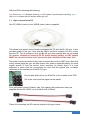
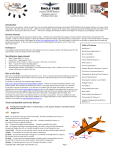
1.2 Gyro connection to aircraft
The connection and orientation of the gyro must be as shown here:
Forwards / front
Left (port) wing
Right (starboard) wing
This will then guarantee the correct operation of the pitch, roll and yaw controls.
Note that positive pitch is defined at an elevator movement resulting in a height gain.
Positive roll is defined as an aileron movement resulting in a starboard (to the right)
directional change. Positive yaw is defined as a rudder movement resulting in a
clockwise (to the right) rotation of the aircraft.
Installation should also be as close as possible to the aircraft centre of gravity.
It is also possible to mount the Gyro up-side-down, by either selecting this option in
the Quick Start tab or the Basic tab. In this case the "P" LED on the front of the BL-3G
Gyro will illuminate red and extinguish when configuration parameters are sent.
(Opposite to normal way round).
Bluelight Technologies Co. Ltd. | BL-3GRC, 3 axis gyro User Manual V2.4
6 of 71
1.2.1 Avoiding unwanted vibration
Although the filtering inside the BL-3G is state of the art, it does not hurt to protect
further by adding some foam protection between the underside of the gyro and the
aircraft base where it is mounted. One method is to use a zeal sheet and tightly affix it
to the base of the BL-3G unit prior to installing into the aircraft.
1.3 Gyro electrical installation
The BL-3G has inputs from an RC receiver and so accepts standard 5v input signals.
(These can go up to maximum 7.4v or down to a minimum of 2.2v with no problems).
The BL-3G signal outputs to drive servos and ESC type units have a maximum high
output of 3.3v. The power output to the servos / ESC units is directly fed through from
whatever battery (normally designated B+), is connected to the gyro. (To either its
input pins or its output pins). As shown below, if higher current servos are used then
separate gyro / servo power supplies (batteries) must be used. The maximum voltage
the gyro can accept for B+ input is 20v, and the absolute maximum current it can
pass to its outputs is 3.0 A .
Note that if there is a power interruption (Power outage, or voltage drop below 3.3v)
to the BL-3G supply then the BL-3G will operate normally for around 1 second before
shutting down or resetting. If the power is re-instated before this time then it will
continue to operate normally.
1.3.1 Typical (low power) system connection
Shown below is a typical system connection:
BL-3G
RC receiver
Pitch control
Roll control
Yaw control
Gyro on/off
Throttle
Input 1
Input 3
Output 1
Output 3
Input 5
Output 5
Servos
Elevator(pitch)
Aileron (Roll)
Rudder (Yaw)
Input 7
Input 2
ESC power output
and throttle input
Elec. Speed
Controller
(ESC)
Electric
motor
(This set-up uses the BL-3G default settings).
The ESC provides power to the RC receiver which then provides power to the BL-3G
Gyro through its signal wires.
Note: The above can be used only if total servo(s) current is less than 2.5A.
Bluelight Technologies Co. Ltd. | BL-3GRC, 3 axis gyro User Manual V2.4
7 of 71
Note the following alternative typical low power connection systems:
BL-3G
RC receiver
Pitch control
Roll control
Yaw control
Gyro on/off
Throttle
Input 1
Output 1
Input 3
Output 3
Input 5
Output 5
Servos
Elevator(pitch)
Aileron (Roll)
Rudder (Yaw)
Input 7
Output 6
Input 2
Throttle
ESC power output
Elec. Speed
Controller
(ESC)
Electric
motor
(This set-up uses the BL-3G default settings).
In this example the throttle output is taken from the BL-3G output also. The
advantage of this method is that the BL-3G can be programmed to have a throttle
safety lock feature, and also throttle curve.
Note: The above can be used only if total servo(s) current is less than 2.5A.
Care must be taken as with any connection method to fully test on the ground first
with full power applied to the motor.
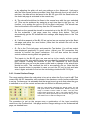
Note that some RC cables are sold with the alternative colour coding of
yellow/orange, red and brown. These are equivalent to white, red and black as
shown here:
Signal
5v
GND
These can be connected together with no problems. It is the RC pilot's responsibility
to ensure the connections provide correct and adequate power as required. Please
also see the tables in section 1.3.4.
Bluelight Technologies Co. Ltd. | BL-3GRC, 3 axis gyro User Manual V2.4
8 of 71
1.3.2 High current system connection
Shown below is a connection scenario with high current servos (>2.5A total):
BL-3G
RC receiver
Yaw control
Gyro on/off
Input 5
Input 7
Output 5
Rudder (Yaw)
Input x
Battery 1
High power
servo
B+ (5v)
Gnd
Battery 2
The second battery, Battery 2, is now connected to the high power servo. Note that
the ground wire to the servo must also be connected either to the ground of Battery 1
(as shown above), or to one of the gyro ground pins (as shown below), or to both.
BL-3G
RC receiver
Yaw control
Gyro on/off
Input 5
Input 7
Output 5
Input x
Battery 1
Rudder (Yaw)
Gnd
High power
servo
B+ (5v)
Gnd
Battery 2
(The above set-ups use the BL-3G default settings).
Note1: If total servo(s) current is 2.5A or more, the servo(s) power MUST be
isolated from the BL-3G gyro.
Note2: It is the model flyer's responsibility to ensure the servos get their required
power and voltage and to ensure the wires are thick enough to ensure this.
(see also below).
Bluelight Technologies Co. Ltd. | BL-3GRC, 3 axis gyro User Manual V2.4
9 of 71
If Battery 1 has enough power then it is also acceptable to connect as shown here:
BL-3G
RC receiver
Yaw control
Gyro on/off
Input 5
Input 7
Output 5
Rudder (Yaw)
Input x
Battery 1
High power
servo
B+ (5v)
Gnd
Although good to save the weight and cost of a second battery, the single battery
must be of good specification to avoid unwanted noise generation during servo
operation. Of course any number of servos can be connected with the methodology
of the diagrams above.
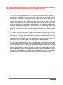
1.3.3 Typical Multi-copter system connection
ESCs and
Electric motors
RC Receiver
Pitch
Power
Roll
Yaw
On/off
Input 1
Input 2
Input 3
Input 5
Input 7
BL-3G
Output 1
Output 2
Output 3
Output 4
Output 5
Output 6
Motor A (front left)
Motor C (back right)
Motor D (back left)
Motor B (front right)
Motor E (left)
Motor F (right)
Battery
(The above set-ups use the BL-3G Multi-copter default settings).
The diagram shows a hex-copter, but a quad-copter can be operated by simply not
connecting motors E and F on outputs 5 and 6 respectively.
Bluelight Technologies Co. Ltd. | BL-3GRC, 3 axis gyro User Manual V2.4
10 of 71
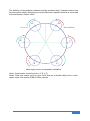
The direction of the propeller rotations must be as shown here. Propeller rotation can
be reversed by simply changing the way the Electronic Speed Controller is connected
to the brushless / electric motor.
A
B
Clockwise
Anti-clockwise
E
F
D
C
Multi-copter motor and propeller installation
Note1: Quad-copter connections are: A, B, C, D
Note2: Real time switch input for gyro on/off acts as a throttle safety lock in multicopter mode. See section 2.2.6.1 of this manual.
Bluelight Technologies Co. Ltd. | BL-3GRC, 3 axis gyro User Manual V2.4
11 of 71
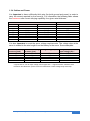
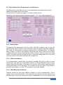
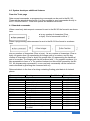
1.3.4 Cables and Power
It is important to have sufficiently thick wire (for both ground and power) in order to
carry the current required by the servo(s). For information the following table shows
the maximum safe current carrying capability for a given wire thickness.
AWG
28
26
24
22
20
18
16
14
Wire thickness
Diameter in inches
Diameter in mm
0.0126
0.0159
0.0201
0.0254
0.0320
0.0403
0.0508
0.0641
Transmission current *
Max current in mA
0.3211
0.0405
0.5105
0.6452
0.8128
1.0236
1.2903
1.6281
228
363
577
918
1,459
2,320
3,690
5,867
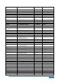
It is also important to meet the servo voltage requirements. The voltage drop at the
servo is related to the wire length from the battery to the servo. Some examples:
Distance battery Distance battery Voltage drop (mV)**
to servo (inch)
to servo (cm)
12
31
40
36
91
110
48
122
150
60
152
190
72
183
220
Voltage drop as % of
input voltage (5v)**
0.7 %
2.2 %
3.0 %
3.7 %
4.5 %
* Figures are for: DC 5v input voltage, and Copper wire. ** Figures assume maximum safe
current for wire thickness. (If less current is drawn then a lower voltage drop will result).
Bluelight Technologies Co. Ltd. | BL-3GRC, 3 axis gyro User Manual V2.4
12 of 71
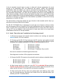
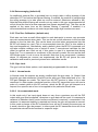
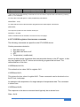
2.0 PC tool and Programmable features
The tool consists of multiple pages used for communicating and setting up the BL-3G
gyro. All the following pages will be discussed in detail in this section. The installation
procedure is detailed in section 6.0 of this document.
o
o
o
Quick Start
Basic
Tools
o
Mixing
o
o
Curves
Advanced 1
o
o
o
Advanced 2
Professional 1
Professional 2
o
o
o
o
Information
Live Data
Upgrade
About
: Standard aircraft configurations and easy loading of script files
: Inputs / outputs, PID controller gains and mix functions
: Connection, saving to file, command inputs and visual testing of
system
: Mixing for non standard aircraft configurations and various flap
modes
: Selection of standard or user defined input curves
: Matches up any RC transmitter/receiver to the gyro. Also trim
adjustments and control surface range set ups are done here
: Real time inputs and features
: PID controller detailed set up, and sensor only mode selection
: Kalman, averaging and High pass filtering,
Gyro lock features, and zero calibration
: System level diagram to confirm set up / configuration
: Analysis of actual data (Oscilloscope mode)
: Firmware upgrade and features upgrade options
: Details of Bluelight Technologies and where to check for
software updates.
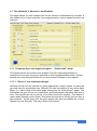
2.1 Tab Quick Start: Standard Aircraft Types
This is the first page and contains and allows very fast parameter selection and
sending options.
Bluelight Technologies Co. Ltd. | BL-3GRC, 3 axis gyro User Manual V2.4
13 of 71
A list of standard aircraft types is given to allow all relevant parameters for such
aircraft to be populated onto the advanced tab pages. Initially the advanced
modification tabs are hidden, but can be accessed by pressing the Enable Tabs
button to the right hand side. Below this button there is an Aircraft Drop n Drag box.
Any standard configuration (.txt) files can be dropped into this box and populate the
other tabs accordingly. (A later tools tab will allow such files to be created). Such files
can also be shared with others and downloaded from Bluelight website. It is important
that when a selection is made that the Send button is pressed to send all the set up
parameters to the BL-3G Gyro.
The last section on this page allows the gyro function to be inverted and for Gyro upside-down mounting. More on this below.
The BL-3G "ICE-MAN" Gyro is designed to work right out of the box with no further
set up necessary with the exception of fine gain adjustments with the supplied screwdriver. A Quick set up procedure will be described here for users who don't want to
use the PC set up software, with comments for those who wish to do some basic
modifications with the PC set up software.
2.1.1 Quick "Out of the box" installation for fixed wing aircraft
o 1: Ensure all servos and aircraft control surfaces are working as expected
without the BL-3G Gyro installed
o 2: Connect up the BL-3G Gyro between the RC receiver unit and the aircraft
servos. All RC receiver outputs should be connected to the BL-3G Gyro inputs
as shown here (make sure the BL-3G Gyro is not connected to a PC):
Rx Elevator
Rx Aileron
Rx Rudder
Rx Channel5
->
->
->
->
BL-3G input 1 (Pitch)
BL-3G input 3 (Roll)
BL-3G input 5 (Yaw)
BL-3G input 7 (Optional, Gyro on/off)
No need to connect the throttle signal at this time.
See diagrams in section 1.3 for physical connections
o 3: Connect the BL-3G outputs to the aircraft control surfaces as detailed here:
BL-3G output 1 (Pitch)
BL-3G output 3 (Roll)
BL-3G output 5 (yaw)
->
->
->
Elevator servo
Aileron servo
Rudder servo
o 4: Now, being careful to make sure your RC Tx is switched ON and with the
throttle at the minimum position, connect the throttle signal from the Rx Tx to
either the BL-3G input 2 or to the ESC unit throttle connection.
o 5: Wait until the BL-3G Gyro blue and yellow lights start flashing, then make
sure the aircraft ailerons, elevators and rudder move as expected when you
activate your RC Tx control sticks.
Bluelight Technologies Co. Ltd. | BL-3GRC, 3 axis gyro User Manual V2.4
14 of 71
o 6: Make sure your control surfaces still move in the required directions as you
activate your RC Tx sticks. If any move in the wrong direction, then you can
instead connect the servo to the inverted signal out. E.g. if your elevator is
incorrect you can move the connection to the elevator servo onto BL-3G output
2 instead of Output 1. Alternatively you can move the slider switch on your RC
Tx to invert the signal. (Alternatively if the input signal can be inverted with the
PC set up software).
o 7: Pick up the aircraft and move it around in all three axes to check if the gyro
function is as expected. I.e. if you make a sharp move in a particular direction,
the gyro function should activate the control surface in such a way as to
combat the sharp movement.
o 8. If the gyro function is in the opposite way than expected then for whichever
control surface or surfaces are incorrect you will need to follow the procedure
here:
Incorrect Elevator Gyro function:
Activate the RC Tx elevator slider switch (if you have one) on your RC tx
to invert the signal. Now connect the elevator servo to BL-3G output 2
instead of output 1. (Or output 1 instead of 2 if you have it swapped).
Incorrect Aileron Gyro function:
Activate the RC Tx aileron slider switch (if you have one) on your RC tx
to invert the signal. Now connect the aileron servo to BL-3G output 4
instead of output 3. (Or output 3 instead of 4 if you have it swapped).
Incorrect Rudder Gyro function:
Activate the RC Tx rudder slider switch (if you have one) on your RC tx
to invert the signal. Now connect the rudder servo to BL-3G output 6
instead of output 5. (Or output 5 instead of 6 if you have it swapped).
The alternative to the above is to use the BL-3G set up software and invert the
inputs from the Basic tab page instead (You will still need to use the alternative
outputs), or if you prefer, to invert the gyro function itself from either the Quick
Start tab page or the Advanced 1 tab page. (In this case no need to use the
alternative outputs). Before doing this, i.e. before connecting the BL-3G Gyro
to the PC via USB, make sure to have power applied to the BL-3G Gyro from
your aircraft system. Alternatively disconnect the servo outputs from the BL-3G
Gyro before connecting the BL-3G Gyro to the PC and re-connect the outputs
after re-programming is complete and the Gyro disconnected from the PC.
Bluelight Technologies Co. Ltd. | BL-3GRC, 3 axis gyro User Manual V2.4
15 of 71
2.2 Tab Basic: Basic operational modifications
This is the first page and contains basic modifications as detailed here. At the bottom
of the page there are two buttons:
‘Default’ button: This sets the page to its factory default values.
‘Send’ button: This sends the data from all pages to the BL-3G. Note that this button
must be pressed otherwise all data on the BL-3G will be lost when it is powered off.
2.2.1 Real-time functions or power bias inputs
Generally the Input1, Input3, and Input5 will be used for Pitch, Roll and Yaw inputs
respectively, as shown on the block diagram of the introduction. This leaves Input2,
Input4, Input6 and Input7 for either real time inputs, i.e. special functions that can be
activated with spare channels on an RC transmitter, or as power bias inputs (for multi
rotor applications). The special functions will be covered in detail under the advanced
2 tab section of this manual. They are active if checked in this basic tab section.
2.2.2 Input Invert
These check boxes allow the input signals for the Pitch, Roll and Yaw to be inverted.
Note that the bars on the Advanced 1 tab page will not change direction, since they
represent the actual input from the RC transmitter.
2.2.3 Gain adjustments
These adjustments basically define how much of an effect the gyro function has. Gain
adjustments for the pitch (X), roll (Y) and yaw (Z) axes PID controllers are set here to
be either ‘low’, ‘medium’ or ‘high’. (The actual values set can be seen under the
professional 1 tab). By default they are all set to Medium gain.
Bluelight Technologies Co. Ltd. | BL-3GRC, 3 axis gyro User Manual V2.4
16 of 71
2.2.4 Active rate LED
A green LED is set to illuminate as follows:
When Gyro off (disabled): When the rate detected on any axis is equal to or greater
than 10 dps.
When Gyro on (enabled): Continuous intermittent flashing.
The LED can be disabled for whatever reason such as to save a little power.
2.2.5 Gyro On/Off switch
The switch is provided in case it is required to switch the gyro off at all times. In which
case the BL-3G can be used simply as a mixing unit. (It can also be useful during the
Control Surface Range set up procedure as explained in section 2.6.3).
2.2.6 Outputs
The outputs can be set to normal meaning, Output1 will be the pitch output for the
elevator control, Output3 will be the roll output for the aileron control, and Output5 will
be the yaw output for the rudder control. The Output2, Output4, and Output6 are just
the 'inverted' versions of the above signals respectively.
Power out onto Output6: This option allows a throttle signal input on any of the inputs
(must be set up from the Advanced 2 tab page), to be output onto Output6. This can
be useful since a special power curve can be set up (see section 2.5) prior to the
signal driving the motor controller. It is also useful to have the Throttle lock safety
feature as detailed next.
2.2.6.1 Throttle Safety Lock
When the power (throttle) signal is programmed to be output onto output6, the output
is at the minimum level (i.e. throttle off) until it is unlocked. To unlock the following
stick positions need to be momentarily performed:
Throttle
Yaw (rudder)
Pitch (elevator)
Roll (ailerons)
: Full low
: Full left (low)
: Full up (high)
: Full right (high)
Note that the positions of the sticks may vary depending on individual combinations of
different RC transmitter input signals and input signal invert settings. To achieve
exactly the same as shown in the diagram above you need to do the following:
o 1: Go to the Advanced 1 page tab, and check which way your control surfaces
are set up. Hit the Active button, and if the following happens:
(i) The Pitch bar moves to the down side as you move your RC Tx pitch
lever up
Bluelight Technologies Co. Ltd. | BL-3GRC, 3 axis gyro User Manual V2.4
17 of 71
(ii) The Roll bar moves to the right as you move your RC Tx roll lever to
the right.
(iii) The Yaw bar moves to the left as you move your RC Tx yaw lever to
the left
(Go ahead and hit the Cancel button when done)
And you have no ticks in the Invert Inputs check boxes on the Basic tab page
then the throttle lock will operate as shown in the diagram above.
o 2: If any of your inputs are contrary to the above, then simply invert them on
your RC Tx unit, or tick the appropriate boxes in the Invert Inputs check boxes
on the Basic tab page. (Ticking the Invert Inputs check boxes will not change
the motion of the bars on the Advanced1 tab, but will ensure your throttle lock
is as shown in the diagram above).
In Multi-copter mode the rotor outputs will be locked until the Gyro on/off switch is
switched to the on position. In Multi-copter mode it is therefore important to make
sure the switch is selected to the Gyro off position to start with. This can be achieved
knowing the RC transmitter operation and checked prior to connecting the BL-3G
Gyro to the multi-copter. The yellow LED light will NOT blink when the Gyro is in the
off mode.
Take care. Immediately after performing the unlock procedure, since the throttle will
be active and follow your RC throttle stick (optionally modified by a throttle curve if
selected on the curves tab page). If the throttle lock feature is not selected, the
throttle will always be active.
2.2.7 Outputs – Bias and invert
Each output can be programmed to have a positive or negative DC bias added to it.
Each signal can also be inverted. This may be useful since for each axis (pitch, roll
and yaw) a positive signal is supplied on the odd Output pins and the inverse on the
even Output pins. If, for example, an aircraft with two servos for the ailerons, requires
that both servos get the same signal then one can be inverted (either Output3 or
Output4 in this case).
2.2.7.1 Stall softener feature (Differential Ailerons)
If you have separate servos for the wings it's possible to add some bias to both
servos to allow them both to deflect up more than down. This helps to reduce the
likelihood of a wing tip stall when aileron deflections are made at high angles of
attack.
2.2.8 Outputs – Aircraft Type
If no inputs are supplied, the BL-3G will generate its own carrier signal pulses to use
as inputs. The pulse width is thus specified here. For airplane applications this must
be set to the mid range. (For multi-copter applications this must be set to minimum,
since no inputs generally means no power should be applied to the rotors). The
selection also ensures up to six motors are supported for multi-copters, and normal
control surfaces for airplanes.
Bluelight Technologies Co. Ltd. | BL-3GRC, 3 axis gyro User Manual V2.4
18 of 71
2.2.9 Outputs – Output connection
The outputs can be set up to drive either standard type (digital or analogue) servos or
motor controllers or non standard so called ‘narrow pulse’ servos. See section 5.0 for
more information. Note that these settings will be inaccessible if the outputs are
modified on the advanced tab page.
Bluelight Technologies Co. Ltd. | BL-3GRC, 3 axis gyro User Manual V2.4
19 of 71
2.3 Tab Tools: Programming and testing
The tools page has various tools available to both program and test the BL-3G gyro.
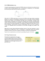
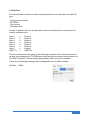
2.3.1 Communications
This section allows the PC to connect to make sure communications with the BL-3G
are ok. It also allows test commands to be sent to the unit and the responses seen.
The above example shows that COM4 is available. This means the serial USB cable
driver has been successfully installed and the cable connected. (But not necessarily
yet the BL-3G to the other end of the cable). On pressing the green open button the
selected port (in this example COM4) is connected to. An error message will display if
the connection fails. If all is ok then the test word ‘Test’ can be written into the write
window. On pressing the red Tx (transmit) button an echo of the word should appear
in the Rx buffer window. If it does not appear an error message will be displayed
instead. The echo means the BL-3G has successfully received the word and has
echoed it back again.
The write window can be used to write a number of commands to the BL-3G. Details
of this are available in the systems developer document. See section 4.0 for details
on the commands available.
The Cycle button is used to cycle through the various baud rates. This option is
available in case the BL-3G baud rate was previously changed and forgotten about.
This option is available only when a port is open and will set the software to the
correct baud rate. Note that for the BL-3G gyro the baud rate is currently fixed at
19,200 b/s.
Bluelight Technologies Co. Ltd. | BL-3GRC, 3 axis gyro User Manual V2.4
20 of 71
2.3.2 File save and read back options
It is possible to save a file onto the PC hard drive (or connected memory) for future
reference with a user defined path and file name for the file. It is also possible to set
up the software so that each time the send button on the Basic tab page is pressed,
the file is also saved. These features allow a file to be saved for each aircraft used
and so the settings can then be re-used to program the gyro in future for the particular
aircraft. The file saved is a simple text file and so can be carefully edited to change
aircraft information if required. Any file can also be read back into the PC set up
software for immediate download to the BL-3G gyro, or for some changes to be made
based on it prior to download to the gyro. The Load file at start option allows a file to
be automatically uploaded into the BL-3G set up tool at start up of the tool. In this way
a previous file that you may have been working on is automatically loaded in at the
start.
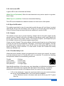
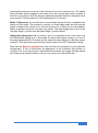
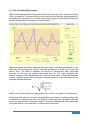
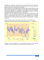
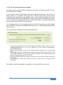
2.3.3 Real time data test
This section allows for the acquisition and graphical display of the gyro X (pitch), Y
(roll) and Z (yaw) rate data. This testing can be enabled and disabled with the buttons
provided. The gyro positive and negative rates are shown in blue colour.
The lower display in green colour shows the positive and negative PID outputs. This
is the control signal that is output to the aircraft.
In the example above there is positive angular acceleration about the X and Y axes
and negative about the Z axis (Blue colour). This means the aircraft has sustained
both a positive pitch and a positive roll rotation. To counter this, the output signals
(green colour) are showing commanded movement of the aircraft control surfaces to
counter these disturbances.
These graphical displays are also used to set up the aircraft pitch and control surface
ranges as detailed in section 2.6).
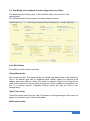
2.3.4 Temperature
The temperature is also shown on this page. It is updated when the thermometer icon
is pressed, provided the connection is still established and the real time data
acquisition function (real time data test) is not active. The data returned is 32 second
averaged data. (Note that if the temperature data is requested prior to waiting 32
seconds the 0 degrees C will be displayed). The ST gyro MEMs chip has a
temperature sensor inside in order to realize the ultra stable performance of the
device. It is only displayed on this page for interest. For best results press the Cal
button and enter the current room temperature (once at least after purchasing the BL3G gyro).
Bluelight Technologies Co. Ltd. | BL-3GRC, 3 axis gyro User Manual V2.4
21 of 71
2.4 Tab Mixing: Non standard aircraft configurations and flaps
This page allows for Flying wing, V-tail and Multi copter mix functions to be
programmed.
The ‘Default’ button sets the page to its factory default values.
2.4.1 Mix Options
Five different modes can be selected.
Flying Wing mode:
Pitch mixed into Roll: This option allows for a flying wing type aircraft to be supported.
This is an aircraft type with no separate pitch control. Hence the ailerons must
support both pitch and roll. When this option is selected Output3 and Output4 are
used as the outputs for the two flying wing servos. When enabled it is possible to set
the % of mixing required. (Flaperon function below can also be used in this
configuration).
Tight Turns mode:
Some Roll signal mixed into the Yaw: This allows a small percentage of the input roll
signal to be mixed into the Yaw for the rudder.
Multi-copter mode:
Bluelight Technologies Co. Ltd. | BL-3GRC, 3 axis gyro User Manual V2.4
22 of 71
Yaw (Z) mixed into Pitch (X) and Roll (Y): This option is used for multi-copter
applications where the yaw control must modify the RPM of each of the central four
motors.
(Thrust on two to be increased and thrust on two to be decreased. This coupled with
the rotational direction of the motors gives the yaw control). When enabled it is
possible to set the % of mixing required.
V-Tail mode:
Pitch (Elevator) and Yaw (Rudder) mix: A slide is supplied to adjust exactly how much
pitch is used and how much yaw is used to output. When enabled one V-Tail servo
output is given on output1 and an inverted version on output2. The second V-Tail
servo is given on output2 with an inverted version on output6, unless output6 has
been set to output the throttle signal.
Note that the Reverse operation box can be ticked if necessary for your particular
configuration. If this is ticked then the application of the particular mix function is
reversed. E.g. if you have the flying wing selected and when you roll the aileron
function is the wrong way round, you can invert it by ticking this box.
2.4.2 Flap Modes
Four different flap modes are supported. For aircraft with actual flaps the flap input
control is selected to be any of the spare inputs to the BL-3G Gyro via the Advanced
2 tab page. The flaps output signal is then given on output 2.
The input flap signal will operate as a toggle switch thus allowing a simple RC
transmitter with a two way switch to perform the control. A transition from low signal to
high signal acts as the active toggle switch.
Mode 1 (Normal): In this mode when the input is switched on and off again the flaps
will move to a "Stage1" position. The "Stage1" position is set up in the Set flaps Stage
1 position box to the right hand side of the tab. When the switch is again activated low
then high again the flaps will move to the "Stage 2 position". The "Stage 2" position is
set up in the Set flaps Stage 2 position box. The settings in these boxes are a
percentage of the half stick range (typically about 500 µs). The speed at which the
flaps are deployed is set up in the Deployment speed box. This time, in seconds, is
the length of time it would take the flaps to move their full range (i.e. from flaps off to
flaps fully extended). On the third toggle of the switch the flaps will return to their
home position.
Note that if a bias input is added from the Basic tab page then this will also appear on
the flap output signal. An output Invert programmed in from the Basic tab page will
also invert the operation of the flaps.
Mode 2 (Airbrake / 'Crow' function): The performance of this mode is the same as
the Normal mode described above, with the following differences: A toggle (switch up
then down) when the flaps are at their Stage 2 deployment position will result in the
flaps staying there and instead both ailerons will move to a certain up orientation. This
to act as an airbrake. While the ailerons move up they will still act as ailerons. How far
Bluelight Technologies Co. Ltd. | BL-3GRC, 3 axis gyro User Manual V2.4
23 of 71
extended they become is set up in the Amount of up mix to ailerons box. The speed
at which these actions happen is the same as for the normal flaps mode, however a
tick box is provided to have the ailerons deployed (activated and also retracted) much
more quickly. This box performs 100% deployment is 2 seconds.
Mode 3 (Flaperons): For aircraft with no actual flaps the flap function is added to the
ailerons in this mode. The operation is similar to normal flaps mode, but this time the
signal is added to the ailerons. An Amount of down mix to ailerons box is provided to
further modulate the amount of down mix added. This percentage acts on top of the
Set flaps Stage 1 position and Set flaps Stage 2 position boxes.
Deployment Speed zero set: In modes 1 and 2 it is possible to set a zero value into
the Deployment Speed box. In this mode the flaps input signal coming in on one of
the pre-programmed BL-3G inputs will be passed through directly to the flaps output
(output2). This then allows an exact flap control based on an RC Transmitter setting.
Note that the Reverse operation box can be ticked if necessary for your particular
configuration. If this is ticked then the application of the particular flap function is
reversed. E.g. if you have mode 1 flaps selected and when you toggle the flaps switch
your flaps go up instead of down, then you can correct it by ticking this box.
Bluelight Technologies Co. Ltd. | BL-3GRC, 3 axis gyro User Manual V2.4
24 of 71
2.5 Tab Curves: Input curve set up
This page sets up the input control curves. The Set up input curves section on the left
details what is to be programmed into the BL-3G gyro. The other sections of this page
are tools to either generate user curves or to aid in selecting the correct curves to
use. The ‘Default’ button sets the page to its factory default values.
2.5.1 Set up
Looking at the left hand side set up section; for each of the axes (power, pitch, roll,
yaw) either a user defined curve can be selected, or a standard one. If a standard one
then the options are given in the pull down menu. The tools described below will aid
in making the selection.
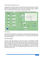
2.5.2 Curve Options
A switch on the right hand side of this section allows for the background graph
(above) to be changed depending if the input of interest is a power curve or a pitch,
roll or yaw (PRY) curve. This section then allows for the various standard curves to be
seen. For example the picture above shows a Tan (Tangent) curve has been selected
and so is shown in the graph area on top of a PRY background. I.e. the stick is shown
going from -100% to +100% with corresponding output also from -100% to +100%. If
a power curve were selected then the background graph would show the curve on top
of a graph as shown here.
Bluelight Technologies Co. Ltd. | BL-3GRC, 3 axis gyro User Manual V2.4
25 of 71
Power graph with stick input from 0 to 100% and
corresponding output also from 0 to 100%
Output
Stick position
The purpose of this section is to allow the curves to be seen such that the curve
required can then be input in the Set up input curves section to the left. It is also
possible to create user own curves as detailed below.
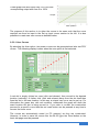
2.5.2.1 User Curves
By selecting the User option, two power curves can be generated and also two PRY
curves. The following display is seen when the user option is first selected:
A red dot is simply clicked on once (click and release), then moved to the desired
location (vertically). A further click (click and release) away from the dot itself then
fixes the dot in the new location. In this way a unique user curve can be set up. For
information the green box, with red numbers, underneath the graph will show the
exact location the dot is being moved to. If you wish to re-start the construction
process for a specific curve then the red reset button can be pressed at any time to
recover the linear curve.
The curves are automatically saved (to PC memory) as they are constructed.
However, in order to save the curves into the BL-3G gyro the Send button on the
basic tab page must be pressed.
Bluelight Technologies Co. Ltd. | BL-3GRC, 3 axis gyro User Manual V2.4
26 of 71
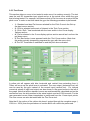
2.5.3 Test Curve
This section allows a curve to be tested to make sure it is working correctly. The test
uses the real RC transmitter input signal and so is the actual curve within the gyro
that is being tested. For example, let's assume that a Flat low curve is required for the
pitch curve. In order to test this inside the gyro the following procedure is performed:
o 1: Standard and also Flat low are selected for the Pitch Curve in the Set up
the input curves section.
o 2: Pitch is selected as the axis of interest in the Test Curve section
o 3: Pitch / Roll / Yaw is selected with the lever switch in the Curve display
Options section
o 4: Flat is selected in the Curve display options section as well as Low from the
pull down menu.
o 5: The Start button is now pressed inside the Test Curve section. (Note that
this action actually temporarily programs the gyro with the new curve).
o 6: The RC Transmitter is switched on and the pitch lever activated.
A yellow dot will appear with blue horizontal and vertical lines extending from it.
These will move as the pitch lever is activated. The new output (horizontal line) will
now be used by the gyro instead of the normal input (vertical line). For interest
numerical values of input and output are also shown in the green boxes to the left of
the graph. Note that all the standard curves are mathematically calculated and so the
conversion from the stick position to the actual output used are 100% smooth. For the
user generated curves linear interpolation is performed from the 11user input points.
The user curves can also be tested with the Test Curve tool.
Note that if the motion of the yellow dot doesn’t extend through the complete range (100% to +100%) then the procedures of section 2.6.1 will need to be performed.
Bluelight Technologies Co. Ltd. | BL-3GRC, 3 axis gyro User Manual V2.4
27 of 71
Once the curves have been selected and the Set up the input curves section
completed, the send button on the basic page tab must be pressed in order to send
all the data to the BL-3G gyro memory. Note that the blue Acquire button can be
pressed in order to acquire the data stored in the BL-3G gyro if required. This will
retrieve all the curves data including the 4 user curves stored within the BL-3G.
2.6 Tab Advanced 1: Advanced modifications
This page allows for the BL-3G gyro to be accurately matched up to any RC
transmitter / receiver system. Typically good quality RC systems will output accurate
minimum and maximum pulses when the control sticks are moved to their minimum
and maximum positions. Normally somewhere between 1 ms and 2ms respectively.
They will also output a central pulse width when the control sticks are left in the
central position. Normally 1.52ms. However these can vary and for not so good
quality systems there will also be variances between different axes (pitch, roll, yaw
and power). Hence it is wise to match up the RC transmitter with the gyro. It is also
then possible to use a low cost transmitter system with the BL-3G gyro and still
benefit from the full motion of the control sticks. The ‘Default’ button sets the page to
its factory default values.
The procedure is to first match up the full range of the control sticks (RC Tx input
matching), then to match up the central stick positions (RC Tx fine trim centre points).
These procedures will be described below:
(Note that the other control inputs not matched are matched to the Power/Throttle
input)
Bluelight Technologies Co. Ltd. | BL-3GRC, 3 axis gyro User Manual V2.4
28 of 71
2.6.1 RC Tx input matching
The matching procedure is detailed here:
o 1: Ensure the RC transmitter has its trim buttons centralized then switch it on
o 2: Press the "Start" button within the RC Tx input matching section. (Note, the
RC transmitter MUST first be switched on).
o 3: Slowly move the control sticks to their minimum and maximum positions.
The bars on the page will show the motion. You will also see center point pulse
width numbers change. (Note that if power is not selected under the Advanced
2 tab page as an input then this will not be displayed).
o 4: Leave the control sticks at their central positions (if power is also used then
this should be left to its minimum position). The PWM values of these central
positions can be seen as the center point values.
o 5: Press the "Match" button. You will notice that the minimum and maximum
positions (PWM pulse widths) will then be recorded in the Min/Max boxes to
the right hand side of the stick motion bars. As will the numbers inside the
Offset boxes.
Bluelight Technologies Co. Ltd. | BL-3GRC, 3 axis gyro User Manual V2.4
29 of 71
The offset simply measures how far off centre the central pulse widths are from the
middle of the min and max ranges ie offset = (min + max)/2 - actual center. This value
is used internally by the gyro to set the central point for its outputs.
The values will be temporarily sent to the BL-3G gyro on completion of this
procedure, but will be programmed into it only when the send button on the basic
page tab is pressed.
Note that the blue Acquire button can be pressed at any time to acquire the existing
Min/Max and Offset values from the BL-3G gyro if required. Note also that the data
within these boxes can also be modified manually if required.
This procedure means that any RC transmitter can be used with the gyro, ie the
standard 1520µs, 960µs and 760µs pulses, but any other also. The values can also
be entered into the boxes "by hand". More information is available by pressing the
green information button.
2.6.2 Control Surface Trim
It is advisable for the aircraft and also the gyro outputs to be matched up and in
perfect trim. This section will detail how this is to be achieved.
Normally the aircraft is trimmed with the RC transmitter during flight. When a gyro is
used this is also normally the way to do it, however it is not necessarily the best way.
A signal input from the RC transmitter normally is a request signal requesting for a
particular angular rotation rate. (Unless a gyro operates in an un-commanded mode,
as detailed in section 2.9.6.2). However, it is not such a good idea to have a rate
request constantly in place as a trim. The reason is that such a request will be
interpreted by the gyro controller as an error to be corrected, and as such will impact
the heading lock feature causing high drift. It is also desirable to have no movement
in the control surfaces when switching the gyro on and off in flight. The philosophy of
the BL-3G gyro is to move the trim settings so as to be as close to the aircraft as
possible, hence to move them to the gyro output.
Red buttons are provided to decrease trim or range, and
green buttons to increase them. The radio button allows
either the trim to be selected or the range. The range allows
the end points to be set. Also available is a blue button to
acquire the trim, and range that may have been previously
set into the BL-3G for a particular aircraft.
The orange button is an auto trim feature for moving the trim from the RC transmitter
to the gyro output. A grey zero button is also supplied to quickly set either trim or
Range values to zero. Note that individual values can be set to zero by simply double
clicking them.
Trim Adjust Procedure
o 1: With the aircraft on the ground and connected up to the PC software the
trim can be adjusted visually. This can be done either with the RC transmitter
Bluelight Technologies Co. Ltd. | BL-3GRC, 3 axis gyro User Manual V2.4
30 of 71
or by adjusting the pitch roll and yaw settings on the Advanced 1 tab page,
with the little square buttons provided. Note that although the trim will work in
real time, the data will not be saved to the BL-3G gyro until the Send button on
the basic tab page is activated in the normal way.
o 2: The aircraft should then be flown in the normal way with the gyro switched
off. (This can be achieved by assigning a real time input to the gyro on / off
function, or by setting the gyro to off on the Basic tab page). The aircraft can
then be trimmed in the normal way from the RC transmitter.
o 3: Back on the ground the aircraft is connected up to the BL-3G PC tool again.
On the advanced 1 tab page press the orange Auto button. This will
automatically get the RC transmitter trim settings, and display them in the Trim
section.
o 4: If all other aspects of the BL-3G set up tool are as required go to the Basic
tab page and press the send button. (Note that the aircraft trim will not be
correct at this stage).
o 5: Go to the Tools tab page, and press the Test button. You will see output
data displayed graphically in green colour. Adjust your RC transmitter trim
controls to remove the green indications. You will also notice the aircraft
control surfaces coming back into good trim.
The inputs to the BL-3G gyro are now set up to be exactly at their central
positions and the trim settings have been successfully transferred to the BL-3G
gyro outputs. Leaving the controls of your RC transmitter at their central
positions the gyro can now be power cycled and no change to the aircraft trim
should be seen. This confirms the trim is successfully set up. Note that the
blue Acquire button is provided in case you exit the PC set up tool and later
enter it again and wish to find out the trim settings inside the BL-3G Gyro.
2.6.3 Control Surface Range
The range section allows the end points to be set up when the Gyro is set to off. That
means with full RC transmitter stick activated, the maximum control surface deflection
is set up. Furthermore it is advisable that the range be set up such that when the gyro
is switched on or off the control surfaces do not deflect to different positions.
With the radio button selecting the Range option, the red
and green buttons allow modifications. Double clicking the
range % number re-sets it back to 100%. The gray zero
button resets all ranges to 100%. The acquire button will reacquire any values previously sent to the BL-3G gyro. The
Auto button has no effect in Range mode.
The procedure to set up the ranges uses a combination of the input sensitivity
controls on the Professional 1 tab page and the Range settings on the Advanced tab
page, as detailed here:
Bluelight Technologies Co. Ltd. | BL-3GRC, 3 axis gyro User Manual V2.4
31 of 71
The PID gain box needs to be set to 11.000, and pots centralized before starting
this procedure, and the range set up correctly with the Gyro off.
Range Adjust Procedure
o 1: With the aircraft stationary, on the ground, and connected up to the PC
software tool the range is adjusted visually. First switch the gyro OFF (either
with a real time input or via the gyro On/Off button on the Basic tab page - if
with the Basic tab button, don’t forget to then press the Send button) and
ensure that when the RC transmitter levers are moved to their maximum
positions the actual control surfaces also reach their maximum positions. If the
maximum position for a particular control surface is not reached, increase the
range by pressing the appropriate green button. If the maximum position is
exceeded then reduce by pressing the appropriate red button. When complete
press the Send button on the Basic tab page to send the new settings to the
BL-3G memory.
o 2: Switch the gyro ON (either with a real time input or via the gyro On/Off
button on the Basic tab page). The input sensitivity controls on the
Professional 1 tab page are now set up such that when an RC transmitter lever
is at a maximum position, the corresponding control surface is also at its
maximum end point. Note that after changing an input sensitivity value it is
necessary to hit the send button at the bottom of the Basic tab page.
o 3: If you have a real time input set to control the gyro on/off function, you can
confirm that the range set up is correct by switching the gyro on and off while
the RC transmitter levers are at their maximum positions. With perfect set up
the control surfaces should not move appreciably when the gyro is switched on
and off. Note that you can also go to the Tools tab page, press the Test button,
and look at the PID data (the green coloured bars) and note that they should
extend left and right and not change very much when the gyro is repeatedly
switched on and off. This confirms the range adjust is successfully set up.
Bluelight Technologies Co. Ltd. | BL-3GRC, 3 axis gyro User Manual V2.4
32 of 71
2.6.4 PWM detailed set up
If special requirements are needed the PWM minimum and maximum values are set
up here. Also the PWM repetition time, ie the period (or frequency). For information
the central pulse width and its frequency are shown.
Note that if a PWM output type is set up in the Basic tab page output connection
section (for example, by pressing the defaults button on that page), then any detailed
PWM set ups made in the Advanced tab page will be overwritten. Similarly if the
defaults button is pressed on the Advanced 1 tab page then the Basic tab page PWM
output connection data will be overwritten. Note that any inconsistent values entered
such as period too small compared to the maximum PWM pulse width then an error
will be indicated. Note that the minimum PWM period that can be set is limited to
1.4ms. For standard servos the selection on the Basic tab page only needs to be
made.
Note that for some older technology analogue servos it may be necessary to set a
PWM period of higher than 15ms. If continuous or intermittent (every few minutes)
vibration is heard / seen then it may be necessary to increase the PWM period.
Typical servo requirements can be seen by pressing the green info button.
2.6.5 Gyro Function Invert
This allows the application of the gyro
correction signal to be reversed. Different
aircraft will have different input signals and
different servo connections and so it may be
necessary to invert the gyro function for a
particular axis.
Bluelight Technologies Co. Ltd. | BL-3GRC, 3 axis gyro User Manual V2.4
33 of 71
2.7 Tab Advanced 2: Advanced modifications
This page allows for more detailed and not so common modifications to be made. It
also allows up to 4 input channels to be programmed to various special functions as
required.
2.7.1 Temporary Gyro rate targets and gains - "Critical time" mode!
This section allows two modes to be enabled. The first mode detailed below is
entered into every time the gryo is switched on with a programmable strobe. And the
second once only during the take off run, when almost full power is first applied.
2.7.1.1 "Gyro on" rate and target changes
Normally the BL-3G will operate by giving appropriate control outputs to make the
gyro rate zero for a particular axis. However this can be modified to any value within
range. (I.e. within range of the data range selected on the Professional 1 page). This
then allows the gyro to lock onto a particular, and fixed angular rate rather than one of
zero. The angular rate can be set up to be either positive or negative. This feature is
useful when teaching novice flyers, and allows the aircraft to quickly recover from a
spin situation. At the same time the gain applied can also be modified by a factor
chosen from the Gain box. The way it works is as follows:
Bluelight Technologies Co. Ltd. | BL-3GRC, 3 axis gyro User Manual V2.4
34 of 71
o During a spin it is necessary to stop the wings spinning,
so a zero roll rate is selected
o If the spin direction is unknown also a zero yaw rate is
selected
o A positive pitch is then applied to stop the aircraft
loosing further height. (50 deg/sec in this example).
o The duration of all the above rates is then set up with the
"Critical time" box. This sets the number of seconds the
rates (and gains) are to last for. The actions (rate and
gain changes) start when the gyro is switched on. An
input is then set up to allow the gyro to be switched on
and off. By default this is Input7, but can be set to any of
the four input options. (See below).
Note that a zero time selection in the "Critical time" box
disables this function.
Note also that if a spin is entered into on purpose, then it
can be decided beforehand which direction the spin will
take (clockwise or anti-clockwise), in which case a spin
opposite rudder rate can also be applied (by entering a
value in the Yaw box). This will then be active at the same
time as the positive pitch. To enhance the recovery (since
the spin will normally be entered into at slow speed), an
increased gain can also be applied with the Gain selection
box.
2.7.1.2 "Take off" rate and target changes
This mode allows special rates and gains to be set during
the take off run. It is entered into only when 30% of full
power is applied. Hence the power input needs to be input
to the BL-3G gyro (or alternatively any spare RC
Transmitter channel suitably set up). In this mode the gyro
is automatically switched on at the start with the normal
pre-programmed settings (The pre-programmed gyro
on/off switch will not operate prior to entering into this
mode). Once 30% of full power is applied, it is assumed
the aircraft is commencing its take off run. At this point the
special gains (and rate modifications, if any) are applied.
Typically this feature allows for straight and smooth take
off runs even in high cross wind situations. To achieve this
at slow speed the yaw gyro gain would typically be
increased (doubled in the example shown here), while
setting all the rate targets to zero. After the pre-defined
"Critical time", of 4 seconds in our example, the "take off"
mode is exited. This means the BL--3G will now operate
as normal. And if a gyro on/off mode was programmed
onto one of the real time inputs this will operate as normal.
Bluelight Technologies Co. Ltd. | BL-3GRC, 3 axis gyro User Manual V2.4
35 of 71
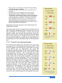
2.7.2 Programmable Real Time Inputs
Input7 is a dedicated real time input. Also, if so enabled (on the basic tab page), the
input signals Input2, Input4 and Input6 can also act as real time inputs. The particular
function is selected to be active on a particular input by checking the appropriate
radio button on the right hand side. The various functions available are detailed here:
2.7.2.1 Gyro On / Off
It is possible to switch the gyro on and off in real time. If the input signal is below (less
than) the central position the gyro is switched on, above it is switched off.
Furthermore, it is possible to allow for any combination of the axes (pitch, roll or yaw)
to be enabled or disabled.
Note that if a system is used that does not have any available RC transmitter
switches then the default is for the gyro to be enabled.
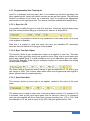
2.7.2.2 Gyro Two Gain Adjust
This function allows a gain multiplication factor to be applied in real time. This then
allows for a high gyro gain during low speed or hover flying, and a much lower gain
during high speed flying. It is also possible to set up an alternative gyro rate range.
This may be desirable if fast flying is suddenly required or if bad weather and strong
winds suddenly appear.
The picture above shows the default values of gain multiplication of 1.5, and a gyro
rate range of ±500. The function takes effect when the programmed input signal is
above (greater than) the central position.
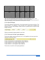
2.7.2.3 Gyro Exact Gain
This function allows an exact gain to be applied, related to the value of the input
pulse.
The above value is used to select one of the below table columns. For example if 0.5
is selected, then as the input signal goes from its minimum value to its maximum
value the gain applied will be an exact gain running smoothly from 1.55 to 7.00. With
the example of 0.5 set, and an input of say 50%, the gain applied will be 4.28.
Bluelight Technologies Co. Ltd. | BL-3GRC, 3 axis gyro User Manual V2.4
36 of 71
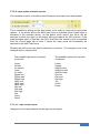
Example set up values:
Input max (100%)
90%
80%
70%
60%
50%
40%
30%
20%
10%
Input min (0%)
0.5
7.00
6.46
5.91
5.37
4.82
4.28
3.73
3.19
2.64
2.10
1.55
1.0
14.00
12.91
11.82
10.73
9.64
8.55
7.46
6.37
5.28
4.19
3.10
1.5
21.00
19.37
17.73
16.10
14.46
12.83
11.19
9.56
7.92
6.29
4.65
2.0
28.00
25.82
23.64
21.46
19.28
17.10
14.92
12.74
10.56
8.38
6.20
Note1: On some RC transmitter the input range may be shown as ranging from -100% to +100%.
Note2: Gains are limited to maximum 35 and minimum 1 (inside the BL-3G Gyro).
Note3: Can check gain actual value by typing qExGainX; into tools page write window and pressing Tx
USB button (qExGainX; for pitch, qExGainY;for roll and qExGainZ; for yaw).
2.7.2.4 Gyro PID Target
This function allows for definite pitch, roll and yaw rates to be set up in real time. This
can be useful if, for example, a very accurate roll of exactly say 50 degrees per
second is required, with perhaps a certain amount of positive pitch to keep the nose
straight and level.
Rates are separately programmable for each axis.
2.7.2.5 Z axis mix to X and Y gain adjustment
This function adds a smooth gain factor (of 0.1 to 9) applied as the input goes from
minimum to maximum value.
Z (yaw) subtracted from X (pitch) positive output (Output1)
Z (yaw) subtracted from X (pitch) negative output (Output2)
Z (yaw) added to Y (roll) positive output (Output3)
Z (yaw) added to Y (roll) negative output (Output4)
This function is used for multi-copter applications.
Bluelight Technologies Co. Ltd. | BL-3GRC, 3 axis gyro User Manual V2.4
37 of 71
2.7.2.6 Power-in mode
The power (throttle) signal can be input onto a real time input and mixed into all the
outputs with a programmable mix factor (0 to 100%) in multi-copter mode. This
function is not available if the PID controllers are switched off.
This function is used for multi-copter applications. Also for the airplane "Take off"
mode as detailed in section 2.7.1.2.
2.7.2.7 Emergency cut off
All output signals will be set to their minimum values when the input is not within the
top 75% of its range.
This then acts as a safety switch, should the controlling micro crash for any reason, or
stop to output a signal, then all BL-3G gyro outputs will go to their default safe values.
The safe value will be as set up under the Basic tab page, in the Aircraft type section.
For applications where the gyro is driving motors this needs to be set to minimum
value (So that power is switched off). In aircraft applications this needs to be set to
mid value, such that all control surfaces are set to their mid positions.
2.7.2.8 I adjust or "Heading Lock" (Also known as AVCS mode)
The "I" referred to here is the Integrative part of the PID controller. This is the part that
adds up all the error terms, i.e. all the accelerations measured by the gyro related to a
particular axis that are not corrected for by aircraft movements. Hence the gain of this
is used for the Heading Lock feature.
It is advisable to leave the I gain on the Professional 1 tab page set to zero. When
enabled by a real time signal larger than the mid level the PID integrative gain is set
up as an absolute number (i.e. not a multiplication gain factor). A typical value of 0.01
can be used for reasonable performance. Note that over time the gyro will lose the
lock direction and so some drift will occur. This will be more pronounced if the input
trim is not set up correctly.
This function is automatically exited when the RC Tx control stick (of a particular axis)
is moved away from the central position.
This function is then enabled when the input is above the midpoint, and disabled
when it is below.
Bluelight Technologies Co. Ltd. | BL-3GRC, 3 axis gyro User Manual V2.4
38 of 71
2.7.2.9 Input power and pitch curves
It is sometimes useful, to be able to switch between one input curve and another.
This is possible by setting up the input power curve select or input pitch curve select
options. If, as shown above the HeliV med curve is selected (when Input2 input is
activated in the example above), as the power curve option, this curve will be
switched to when the input on the select input goes above the 50% position. If the
programmable input is less than the 50% level then the normal curve as selected
from the Curves page tab is used, if above the input curve will immediately be
switched to the HeliV med curve.
Similarly the pitch curve can also be switched in real time. (To a tangent curve in the
example above, using Input4).
The available options for the power
curves are:
The available options for the pitch
curves are:
Linear
Square
Inv square
Cube
Inv cube
Sigma low
Sigma med
Sigma high
HeliV low
HeliV med
HeliV high
Flat low
Flat med
Flat high
Tan
User1
User2
Linear
Square
HeliPitch low
HeliPitch med
HeliPitch high
Flat low
Flat med
Flat high
Tan
User3
User4
2.7.2.10 Flaps Control Input
Assignment of an input channel for the flaps control signal
Bluelight Technologies Co. Ltd. | BL-3GRC, 3 axis gyro User Manual V2.4
39 of 71
2.8 Tab Professional 1: Professional 1 modifications
This page sets up specific gyro control parameters as detailed here. The
‘Default’ button sets the page to its factory default values.
2.8.1 Pitch, Roll and Yaw axes PID controllers
The pitch, roll and yaw axes PID controller parameters can be set up individually. P
gain is the proportional gain, I gain is the integrative gain and D gain is the differential
gain. Integral windup is the tendency for the integral part to keep adding up
(especially during static conditions) and could go on to a very high value indeed if not
kept in check. The integrative part of the PID controller is actually used as a heading
lock for aiplane applications. (See section 2.7.2.8) It is not advisable to modify this
setting on this page, but instead it can be modified via a real time input (see the
advanced tab section). By using a real time input the I gain for the heading lock can
be enabled and disabled during flight, thus avoiding the integral windup problem
during static conditions. The overall effect of the gyros is modified with the PID gain
box. This then is the most important parameter to modify for individual aircraft types
and performance requirements. Hence it is highlighted in yellow, and also has buttons
to the right for quick up and down modifications. The overall limits to the gain values
are between 1 and 35.
The small potentiometers are shown here too. These are modified with a small
screwdriver on the gyro PCB itself. Hence the final gain is a combination of the gain
set up in the PID gain box as detailed above. In fact the potentiometers adjust the
gain set up in the PID gain box by a certain positive or negative percentage. The
potentiometer setting is indicated in the Manual gain adjust text. The final gain is
show in the yellow Total gain box. The purpose of the PCB potentiometers is to allow
Bluelight Technologies Co. Ltd. | BL-3GRC, 3 axis gyro User Manual V2.4
40 of 71
the gain to be easily and quickly modified in the field without the need to connect to a
PC each time.
The input signal to the PID controllers can also be set up here. This is the sensitivity
of the input control of the RC transmitter (when Gyro is ON). For example, if a small
pitch is requested by moving the pitch lever on the RC transmitter up, this will send a
command to the pitch PID controller to request a particular rate, for example a 10
degrees per second rotation. Whether this is a small movement of the transmitter
lever or a larger one is set up using this input sensitivity box. (Please also see section
2.6.3.2 on control surface range set up).
The PID controllers can also be disabled, in which case only raw gyro rate data is
output. This feature is for advanced users wishing to use the gyro purely as a sensor
with no control output.
2.8.2 Automatic Gain Control (AGC)
This feature limits the gain if unwanted feedback oscillations start to set in. These
oscillations are similar to flutter and are caused when high gain levels are used. This
is similar to using a microphone too close to the speaker output. The speaker output
will feedback into the microphone, which will again further amplify the signal. This
positive feedback can also happen with aircraft control surfaces.
2.8.3 Rate data range
The range over which the gyros operate is defined here, with values in degrees per
second (dps). Note that the high pass filter cut off frequency options (on the
professional 2 tab page) are modified depending on the data range chosen. If a not
so large aircraft is flown in very turbulent weather conditions at high speed then rather
large accelerations may be experienced by the craft. In such conditions it may be
advisable to set a range of either ±500 or even ±2000 dps. (It is also possible to
modify these with a real time input as can be seen on the advanced tab page).
2.8.4 Gyro data rate
The Gyro data rate is specified here. This is the rate at which gyro data is taken out of
the ST gyro device onboard the PCB. For each rate there is a corresponding cut off
frequency that has also to be specified.
Bluelight Technologies Co. Ltd. | BL-3GRC, 3 axis gyro User Manual V2.4
41 of 71
2.9 Tab Professional 2: Professional 2 modifications
This page sets up more specific gyro control parameters as detailed here. At the
bottom of the page there is one button:
‘Default’ button: This sets the page to its factory default values.
2.9.1 Kalman filters
The Kalman filter parameters are set up here. This filter is used to eke out the real
data from the typical inherent noise associated with any signal acquisition hardware.
The reader is encouraged to study the Kalman filter in dedicated texts. The Kalman
filter includes a model of the physics associated with the aircraft and its motion
(rotation about each axis) caused by the control surfaces. This is known as the state
model. The state model then aids the filter in accurately being able to find the most
accurate value for the actual rotational rate of each axis.
2.9.1.1 IM (Inertial Mass)
It is unreasonable to expect any commercially available RC gyro to excel for every
aircraft type, size and user requirements. Hence an IM (Inertial Mass) input is given
here to get some estimation of the size of the aircraft. This number should be set to
the aircraft weight for normal flying. This number can be set higher if the aircraft is
generally flying slowly, or lower if it is intended to fly at high speeds.
2.9.1.2 MN (Measurement Noise)
Different aircraft will also have different vibration or noise characteristics. This is
another input to the Kalman filter. The actual live gyro data can be seen from the live
data tab page, and so the setting here can be considered to be x10 the typical noise
Bluelight Technologies Co. Ltd. | BL-3GRC, 3 axis gyro User Manual V2.4
42 of 71
variation seen. A typical value for electric flyers is around 12 dps. Generally the value
used will be increased, for example, for noisy petrol engine aircraft or reduced for
gliders or electric flyers.
2.9.1.3 AN (Acceleration Noise)
The acceleration noise is the vibration of the aircraft for all sorts of external factors
such as, aerodynamic design, control surface flutter, loose hinges on control
surfaces, bad weather etc. Acceleration noise is the actual accelerations experienced
by the aircraft rather than the noise in the inaccurate measurement of these
accelerations by the gyro (which is the measurement noise mentioned above).
Typically this can be set to a reasonably low level of 4 dps, but can also be increased
for poorly designed aircraft.
Note that the Kalman filter can be switched off for each axis and only data averaging
can be used instead if required.
2.9.2 Predictive mode
The Kalman filter contains a physical model of the aircraft and its motion (the state
model). This model is a generic model since clearly not all parameters of an individual
aircraft are available to it. This physical model to some extent models the aircraft
dynamics. Hence one aspect of the Kalman filter is that for applications where large
dynamic changes are occurring, such as for aircraft performing aerobatics or any
large control surface movements the predictive mode will help the Kalman filter to
calculate more accurate actual gyro rates from the raw sensor inputs. For aircraft
such as hovering multi-copters it is better to disable this feature. This feature should
also be disabled if an offset is used (such as an input PRY curve where the central
stick position gives a non zero output). Note that even if enabled the feature will
automatically be disabled inside the gyro during heading lock mode. (See advanced 2
tab).
2.9.3 High Pass Filter (HPF)
The HPF is always enabled, but the cut off frequency can be adjusted. The available
cut off frequency options depend on the data rate chosen in the Professional 1 page.
The options are shown here:
ODR (Hz)
100
200
400
800
Cut off frequency (Hz)
8
4
2
1
15
8
4
2
30
15
8
4
56
30
15
8
0.5
1
2
4
0.2
0.5
1
2
0.1
0.2
0.5
1
0.05
0.1
0.2
0.5
0.02
0.05
0.1
0.2
0.01
0.02
0.05
0.1
ODR is output data rate.
When enabled, defaults are shown in bold text.
Particular low frequency noise can therefore be removed from the gyro measurement
should this be a problem with particular aircraft.
Bluelight Technologies Co. Ltd. | BL-3GRC, 3 axis gyro User Manual V2.4
43 of 71
2.9.4 Data averaging (default off)
An additional optional filter is provided here to simply take a rolling average of the
data after LPF, but before the Kalman filtering. If enabled, the number of samples that
the rolling average is to take effect on must be entered. (Maximum allowed is 99).
Note that this simple filtering will smooth out any noise in the gyro measurements but
will do this at the cost of a slow response time (known as phase lag). This filter can be
applied at the same time as the Kalman filtering if required. If enabled it is
recommended that numbers not much larger than single digit numbers are used.
2.9.5 Fine Zero Calibration (default auto)
Each axis can have a small offset added to each data point to ensure very accurate
zero rate measurement when static. This can be set up with reference to the live data
display on the live data tab. This can be done once and when programmed into the
BL-3G will always be used (This is recommended since the Gyro is ultra stable in
time and temperature). Alternatively, and by default, when the BL-3G is powered up it
will take multiple readings over a period of some 7 seconds and calculate its own
offset for optimal zero level set up. If this option is used it is important that during
these first 7 or so seconds no movement of the aircraft is made. As soon as the blue
LED blinks again it is ok to move the aircraft. Note that if any movements / rotations
above 18 degrees per second are experienced, the BL-3G will ignore the auto
calibration and revert to previously stored auto calibration results.
2.9.6 Gyro Lock
The gyro lock has three options, each separately programmable for each axis.
2.9.6.1 Normal mode
In Normal mode the outputs are simply modified with the gyro data. I.e. Output1 has
the pitch gyro data subtracted, Output2 has the pitch gyro data added and so on. No
PID gain changes are made. The input from the RC receiver is taken to be a rate
command. In other words a particular position of the RC transmitter lever will send a
pulse of a certain width to the RC receiver, which the BL-3G gyro will interpret as a
request for a specific rate of turn to be applied to the particular aircraft axis.
2.9.6.2 Un-commanded mode
In this mode only if an input signal does not vary from a previous one will the PID
output with gyro data be applied, otherwise no gyro data will be used. It is assumed a
variance is indication that a control surface movement is required / commanded. If no
variance it is assumed stability is required and hence the gyro will operate as normal.
In this mode a change of the RC transmitter lever will act in exactly the same way as
it would, should no gyro be present. In other words the RC transmitter lever will move
the particular aircraft control surface to a specific angle.
Bluelight Technologies Co. Ltd. | BL-3GRC, 3 axis gyro User Manual V2.4
44 of 71
2.9.6.3 Proportional mode
In this mode the rate of change of the gyro lock gain factor needs to be set up. I.e. the
gain at the central PWM pulse width (GCen) is set. For example a gain factor of 1 will
mean there is no change in the gyro final gain at the central PWM position (i.e. PWM
centre typically at 1.5ms), but at the extreme positions (i.e. typically at 1ms and 2ms)
the gain is multiplied by a factor (GMax), which by default is set to 1.5. If the Invert
option is selected the gain at the central PWM pulse position (PWM centre) is set to
the maximum (GMax) and falls off (linearly) either side until at the extremes it
becomes the minimum value (GCen).
Gain
factor
GMax
GCen
PWM width
PWM
min
PWM
Centre
PWM
max
For the rudder, as an example, the PWM min position is at the full left rudder position and PWM max is
at the full right rudder position.
If the Invert box is checked then the gain factor applied is as shown here:
Gain
factor
GCen
GMax
PWM width
PWM
min
PWM
Centre
PWM
max
Bluelight Technologies Co. Ltd. | BL-3GRC, 3 axis gyro User Manual V2.4
45 of 71
2.10 Tab Info: Set up information display
This page shows the set up parameters in a graphical format and is updated in real
time as set up changes are made.
The functions and how they are enabled is shown in the centre with the inputs to the
left and the outputs to the right. The PWM pulse train is also shown as set up. The
above is the default view. The software version inside the BL-3G is displayed at the
bottom left automatically after successful communications has been set up (see next
section).
The purpose of this page is simply to make sure the gyro has been set up as
required. Note that X is pitch, Y is roll and Z is yaw. The page, as shown above, is
informing the connection to the aircraft is as follows:
o
o
o
o
o
o
o
o
o
The USB is connected. The UART port is also available, but not connected.
Output1: Connect to the pitch servo of the aircraft. (If your servo is in another
orientation then the inverse signal is available on Output2).
Output3: Connect to the roll servo of the aircraft. (If your servo is in another orientation
then the inverse signal is available on Output3). If two servos are used then Output3
and Output4 can both be used. (If it is required that they both have the same signal
then Output4 can be inverted from the Basic tab page).
Input2 is set up as a real time input with the throttle in function mapped to it.
The throttle output has been mapped to Output6.
Input7 is set up as a real time input with the Gyro on/off function mapped to it.
The gyro is ON and has Kalman and high pass filtering enabled, but data averaging
disabled.
The input curves are all set to linear.
The gyro lock is set to normal mode.
Bluelight Technologies Co. Ltd. | BL-3GRC, 3 axis gyro User Manual V2.4
46 of 71
o
o
o
o
Rate targets are all set to 0, meaning the critical time mode is disabled. (NZ will
appear, meaning Non Zero, if target rates are set up in the Rate targets section of the
Advanced 2 tab page).
The BL-3G gyro will output signals with minimum 1.1ms and maximum 1.94 ms pulse
widths, with a frequency of 15ms.
The software version number is available when the "Click when connected" text is
clicked.
If no input signals are supplied the inputs will default to the mid range value.
Note: Input1 - ΔX simply shows that the gyro correction to pitch will take place in the opposite direction
to the pitch motion caused by some external disturbance.
IMPORTANT NOTICE:
The information tab page is a good indication how the system should be
connected according to the settings selected in the BL-3G set up tool,
however:
THE PERFORMANCE OF THE AIRCRAFT SHOULD BE TESTED ON
THE GROUND PRIOR TO ANY FLIGHT.
Checks should also be made that the gyro function is the correct
way round for any disturbances and that any flap functions operate
the correct way round too.
Bluelight Technologies Co. Ltd. | BL-3GRC, 3 axis gyro User Manual V2.4
47 of 71
2.11 Tab Live data: Data analysis
When both developing and flying aircraft such as fixed wing, multi-copters and other
UAVs, the amount of induced noise into the data involved with the system stability is
of paramount importance. It is for this reason that a page is dedicated to looking at
the actual data when the system is in full operation.
Options are given to view the raw gyro rate data (Raw), or the post processed, i.e. the
data after the filtering blocks (Post). Raw data is displayed in black colour, and post
data in blue. The data is viewable as though an oscilloscope were connected
internally. In this way the system parameters such as LPF, data averaging and
Kalman filtering can be adjusted and the results actually seen. A standard deviation
function (actually, square root of the bias-corrected variance) is also calculated for the
particular data set acquired.
Where x bar is the data set average, and N is the number of samples in the data set.
Internally a 5ms loop is run prior to using the data to generate the outputs. Hence with
the default 100 samples, the time axis is split into 5ms segments. By default 100 data
points are acquired (0.5s total time period). This can be changed with the time axis up
and down buttons, and reset back to 100 with the reset button.
Bluelight Technologies Co. Ltd. | BL-3GRC, 3 axis gyro User Manual V2.4
48 of 71
Regarding the vertical axis, options are given to automatically scale the data to fit
onto the screen. (This is the default set up). Otherwise user own scaling can also be
performed with the up and down buttons provided.
With the aircraft static and engine/motor switched off the noise level should be within
about ±1 degree per second. The static level can be adjusted with the controls on the
Professional 2 tab page. This is detailed in section 2.9.5 on Fine Zero Calibration.
The signal can also be used to assess the most appropriate parameters to use when
setting up the Kalman filters, as discussed in section 2.9.1.
Note that an A/C D/C coupling button is also provided. This is useful to centre the
waveform in the case of a post analysis where a DC level is present from a trim
offset, or a power signal (in the case of a multi rotor application) or if the Kalman
predictive mode is enabled (This will result in a small DC offset in static conditions).
Also in the case of very small raw gyro data offsets (in Raw data view, i.e. prior to
calibration).
A typical static gyro trace is shown below to get a better idea of the noise floor:
If the gyro is correctly calibrated (i.e. not moved during power up if set to auto fine
calibration mode), the waveform will stay within around ± 0.5 degrees / sec.
Bluelight Technologies Co. Ltd. | BL-3GRC, 3 axis gyro User Manual V2.4
49 of 71
2.12 Tab Upgrade: Upgrade firmware
There are two upgrade paths. The first box entitled Software Upgrade (BL-3G gyro
firmware), allows for the actual firmware of the gyro to be upgraded. Updated files will
be available for download from Bluelight website, if and as they become available.
The second box entitled System software upgrade enables the UART
communications port on the BL-3G gyro as well as the special commands to allow
programming and data extraction from the BL-3G gyro. This is for systems
developers wishing to install the BL-3G onto their own PCBs or otherwise onto their
own developed systems.
Bluelight Technologies Co. Ltd. | BL-3GRC, 3 axis gyro User Manual V2.4
50 of 71
2.12.1 BL-3G firmware upgrade
The following procedure can then be used to upgrade the gyro unit:
o
o
Connect the gyro to the PC via the mini USB connector
Hit the Launch upgrade button. A new window will pop up, as shown here:
o
Making sure the Gyro connected indication is visible in the first little box, three easy
steps follow.
Step 1: Choose the file (*.efu) to download which should have been saved to your PC
hard drive or connected memory device.
Step 2: Enter the 40 digit key word given to you by Bluelight Technologies. If you don’t
have this simply send a mail to [email protected] requesting one. Press the
Check button when done
Step 3: Press the Upgrade button. Progress will be displayed in the windows below.
The upgrade will progress in two phases. Phase one is the erasing of the previous
firmware, and phase two the programming of the new firmware. The complete reprogramming time should be less than 20 seconds.
When complete go ahead and press the Quit button. You must now unplug your Gyro
from the PC and also from any external power source to power cycle it.
o
o
o
o
Bluelight Technologies Co. Ltd. | BL-3GRC, 3 axis gyro User Manual V2.4
51 of 71
2.12.2 BL-3G system developer upgrade
In order to start to use the UART and special commands a license must be acquired.
Two licenses are available:
1) A free demo license (Developer demo) which allows all features to be used for a
fixed duration of 5 minutes. After this time a BL-3G gyro power cycle will be
necessary, then the features may again be used. In this way the developer can check
out the features. Note that the BL-3G PC set up program can be configured to run all
its set up entirely by using the UART port rather than USB. In this way a developer
can test and see the UART working correctly.
2) A full demo license. Once programmed into the BL-3G gyro the gyro will operate
with full UART and special commands mode all the time. A small charge will be made
for this license.
The procedure for installing a license is described here:
o
o
o
o
o
Acquire the appropriate license from Bluelight technologies. Either send an e-mail to
[email protected] or see our website for more details (www.bluelighttech.com/Buying.htm)
Simply copy and paste, or type in the license number into the box on the left hand
side.
A message will pop up inside the box to indicate the type of license and if valid. If valid
and a USB connection to the BL-3G exists (not UART only connection) then the
license will be programmed into the BL-3G.
Press the Update button to the right to ensure the correct license is indeed inside the
BL-3G gyro.
For the features to take effect inside the BL-3G a power cycle of the gyro will be
necessary.
The additional features available are detailed in section 4.0 of this document
Bluelight Technologies Co. Ltd. | BL-3GRC, 3 axis gyro User Manual V2.4
52 of 71
2.13 Tab About: Bluelight Technologies
The last tab simply gives contact information about Bluelight Technologies (the
designers of the BL-3G gyro) and where to find more information and software
updates / downloads.
Bluelight Technologies Co. Ltd. | BL-3GRC, 3 axis gyro User Manual V2.4
53 of 71
3.0 Detailed Specifications
3.1 Functional specification
Feature
Quick Start
Standard Aircraft
Gyro function
Drag 'd drop box
Send to Gyro
Mounting
Basic
Stability
Gyro Gain adjust
Inputs
Outputs
Output Mixing
Output options
Servos
Send to Gyro
Tools
Save to file
Read from file
Connection check
Command mode
Quick check
Temperature
Mixing
Aircraft types
Flaps
Curves
Types
Advanced 1
Fine matching
Trim adjust
Range adjust
Servo advanced
Gyro function
Advanced 2
Crash avoidance
Straight take-off
Heading lock
Gyro on/off
Gyro two gain
Functional specification
A list of standards aircraft to choose from
Ability to change the Gyro function direction for each axis
Drag and drop box for aircraft parameter .txt files
Button to send all parameters to the BL-3G Gyro
Up-side-down mounting option
Pitch, roll, yaw axes with programmable gains
Via PC software or rotary switches on the PCB
Pitch, roll, yaw, and optional x4 inputs (power and/or RC Tx switches). Ability
to invert the input signal
Pitch, roll, yaw control and also power (optional)
For "Flying wing" (no rudder), "multi copter", dual servo applications
Addition of bias (sub trim), invert signals
Can connect to Digital, analogue, speed controller, or Narrow pulse.
Button to send all parameters to the BL-3G Gyro
All unit set up data can be saved to PC HDD or connected memory. Any
number of set ups can be saved. Typically one per aircraft type.
Any pre-saved files can be loaded from PC to the BL-3G set up program.
The PC tool checks to make sure communication with the gyro unit is possible
Commands can be sent to the unit and responses received
Graphical bars on the PC set up tool are provided to show the gyro can
measure ok and can also generate outputs to the control surfaces to counter
the measured rotations.
Temperature sensor read out and calibration
Mixing for flying wing (delta wing), V-tail, and multi-copter. Tight turns feature
(mixing some roll into the yaw)
Normal flaps, airbrake function, flaperon function, and flap pass through. All
with function application reverse option. (Two stage flaps supported)
X4 user defined curves (11 points) to adjust power, pitch, roll and yaw inputs.
17 pre-defined curves (smooth curves, ie infinite points)
Matches with any RC transmitter (Tx) for optimal performance
Adjust pitch, roll and yaw trim
Adjust pitch, roll and yaw movement end points
Programmable output signal to support any servo or controller.
Ability to invert the gyro function on a per axis basis
Set 'rate' targets for pitch up and zero roll for programmable time/gain
Set 'gain' target for zero heading drift for programmable time and gain
Set with RC Tx switch off, for programmable time
Set RC Tx switch to switch gyro on and off
Set RC Tx switch to flip between low and high gain for slow and fast flying.
Bluelight Technologies Co. Ltd. | BL-3GRC, 3 axis gyro User Manual V2.4
54 of 71
Gyro exact gain
Constant Roll
Constant Pitch
Multi-copter mix
Power in mode
Emergency cut-off
Rotational lock
(Pitch, roll, yaw)
Curve selects
Flap selection
Professional 1
Internal gyro setup
Strong wind mode
Mix function only
AGC
Professional 2
Aircraft type and
environment
matching
Gyro zero
calibration
Gyro lock modes
Control surface
flutter support
Information
Graphical display
Live data
Oscilloscope mode
Upgrade
BL-3G firmware
Developer upgrade
Set RC Tx signal to give an exact gain setting
Set 'Gyro PID target' to desired roll rotational rate, with (optional) pitch rate set
to zero to give nice clean and regular aircraft barrel roll performance
Set 'Gyro PID target' to desired pitch rotational rate, with (optional) roll rate set
to zero to give nice clean and regular aircraft loop performance
Gain adjust for the mixing of yaw into all multi rotor motor outputs
Allows the power signal to be mixed into all output signals. Used for QR since
outputs are all connected to motor controllers
All control surfaces go to their safe positions if a programmable input signal
stops transmitting. Safe is central positions for airplane applications or
minimum positions for Multi-rotor applications
Heading lock, roll lock or pitch lock activated (with programmable gains) when
an RC Tx switch is toggled
An RC Tx switch can be programmed to switch between curves for either
power or pitch axes.
Flap input channel selection
Detailed set-up of the PID controllers for the pitch, roll and yaw gyro functions.
Allows modifications of how the gyro measures the aircraft rotations about
pitch roll and yaw axes, ie its sensitivity. Can set to ± 2000 deg/sec range in
case of very turbulent and bad weather flying.
Disable the gyro functions for gyro to act as mixer / curve unit only
Automatic Gain Control to limit flutter type oscillations
Can adjust the internal Kalman filters to match the environmental noise and
vibration of the aircraft.
Also available is an averaging filter for very high noise environments where
gyro high speed operation is not so critical.
The Kalman filtering can also be adjusted to match the aircraft model size for
very fine tuning (Inertial mass parameter).
The gyro zero calibration can be set to manually or automatically each time the
unit is switched on. Manual set up is achieved graphically.
The 'gyro lock' feature can be set to 'normal' of 'un-commanded'. User
preference for how the aircraft operates when the gyro is switched off. (See
user manual for details).
It can also be set to proportional mode, see below.
When control surfaces extend to their maximum reaches, turbulence and or
flutter may set in, in which case it may be necessary to have an automatically
higher gyro gain proportional to the control surface location. (Alternatively this
can be set to operate inversely proportional).
A display is provided to give graphical feedback as to the unit set up
The PC tool acts as an oscilloscope, with standard deviation read-out, to show
the gyro measured data, pre and post filtering. This to characterize the aircraft
noise environment.
The BL-3G firmware can be upgraded as updates become available.
To allow for the PCB module to be installed into a developers own system a
UART connection might be useful for programming and operation of the final
system. Also many new commands are made available. To enable these
features it is necessary to purchase an upgrade license. A free demo license is
also available.
Bluelight Technologies Co. Ltd. | BL-3GRC, 3 axis gyro User Manual V2.4
55 of 71
3.2 Hardware specification
Parameter
Test condition*
X, Y and Z gyro
Full scale (FS) rate
range
User
programmable
Sensitivity
Zero rate level change
vs. temperature
Absolute maximum
acceleration
PWM
Input channels
Output channels
PWM accuracy
PWM input pulse high
PWM input period
PWM output pulse high
PWM output period
Communications
USB (mini) interface***
USB power sourcing
UART channels
UART speed
Interface voltages
PWM input voltage
PWM output voltage
PWM output current
Temperature
Temperature sensor
output change vs.
temperature
Temperature sensor
refresh rate
Operational
temperature range
Power
Input voltage (Vdd)
Operational current
consumption
Power routing
(To driver servos/ESC)
0
Typical**
FS = ±250 dps
FS = ±500 dps
FS = ±2000 dps
-40 to +85 0C
Sensitivity change vs
temperature
Rate noise density
Digital zero rate level
*Test conditions at 25 C
Min
At 50 Hz BW
FS = ±250 dps
FS = ±500 dps
FS = ±2000 dps
FS = ±250 dps
FS = ±2000 dps
For 0.1 ms
All outputs
2
1000
100
101
Full speed
Max
Units
± 250
± 500
± 2000
8.75
17.50
70
±2
dps (degrees
per second)
0.03
± 10
±15
± 75
± 0.03
± 0.04
dps/sqrt(Hz)
dps
x7
x6
1,520
10,000
1,500
10,000
mdps/digit
%
dps/0C
10,000
g
1
20,000
20,001
65,000
65,001
µs
µs
µs
µs
µs
64
100
Bytes/ms
mA
x1
All inputs
All outputs
Drive current
19,200
19,200
b/s
2.2
7.3
3.3
V
V
mA
5
-1
0
1
Hz
-30
At 5v input supply
voltage
Any PWM input to
any PMW outputs
C/digit
+85
0
C
3.3
5
45
20
V
mA
0
2.5
3.0
A
**Typical specifications are not guaranteed
***IEC 61000-4-2 level 4 compliant
Bluelight Technologies Co. Ltd. | BL-3GRC, 3 axis gyro User Manual V2.4
56 of 71
4.0 System developer additional features
From the Tools page
Data request commands, or programming commands can be sent to the BL-3G.
These are the standard commands. It is also possible to send commands directly to
the ST L3GD20 device. These two options are detailed hereunder.
4.1 Standard commands
When a read only data request command is sent to the BL-3G the format is as shown
here
n is any number of characters (Char
or byte). End of command is with a “;”
When a programming data command is sent to the BL-3G the format is as shown
here
n is any number of characters (Char or byte). i is any number of characters (Char or
byte) not greater than 10 representing the integer part of a number, and f is any
number of characters (Char or byte) not greater than 10 representing the fractional
part of a number. The integer part can be prefixed with “-“ for negative numbers. It is
also acceptable to have a “+” for positive numbers but this will be ignored by the BL3G. All programming commands (i.e non read only commands) can be turned into
read commands by prefixing the command with a q.
Returned data is in the form of a string containing floating point data to 4 decimal
places.
Command
Meaning
Data request (read only)
Send Value
Return Value
Test
XInRaw
YInRaw
ZInRaw
P7InRaw
P6InRaw
P4InRaw
P2InRaw
qXRAW
qYRAW
qZRAW
qXPST
qYPST
qZPST
qPotX
-
Sting "Test"
String (data to 4dpl)
String (data to 4dpl)
String (data to 4dpl)
String (data to 4dpl)
String (data to 4dpl)
String (data to 4dpl)
String (data to 4dpl)
String (data to 4dpl)
String (data to 4dpl)
String (data to 4dpl)
String (data to 4dpl)
String (data to 4dpl)
String (data to 4dpl)
String (data to 4dpl)
Communications test
Pitch in (Input1) PWM width
Roll in (Input3) PWM width
Yaw in (Input5) PWM width
Input7 PWM pulse width
Input6 PWM pulse width
Input4 PWM pulse width
Input2 PWM pulse width
Raw gyro X axis data
Raw gyro Y axis data
Raw gyro Z axis data
X axis post processed data
Y axis post processed data
Z axis post processed data
X axis potentiometer gain
0 to 4095
Bluelight Technologies Co. Ltd. | BL-3GRC, 3 axis gyro User Manual V2.4
57 of 71
qPotY
qPotZ
qExGainX
qExGainY
qExGainZ
qAvTemperature
Status
Version
ProdID
Self test
Y axis potentiometer gain
0 to 4095
Z axis potentiometer gain
0 to 4095
Real time exact gain pitch
Real time exact gain roll
Real time exact gain yaw
32 second averaged temp.
Status information
Software version number
Hardware product ID
Error (0) or all ok (1) message
-
String (data to 4dpl)
-
String (data to 4dpl)
-
String (gain value)
String (gain value)
String (gain value)
String (data to 4dpl)
String (error code)
String (version ID)
String (Prod. code)
String
Programming * (write and read - prefix with 'q' to read)
XAxisGain
YAxisGain
ZAxisGain
ActivityLED
ExtYawMix
GyroYawMix
PWM_out1Bias
PWM_out2Bias
PWM_out3Bias
PWM_out4Bias
PWM_out5Bias
PWM_out6Bias
PWM_out1Inv
PWM_out2Inv
PWM_out3Inv
PWM_out4Inv
PWM_out5Inv
PWM_out6Inv
PWM_inDefault
XPPIDgain
XIPIDgain
XDPIDgain
XPIDwindup
XPIDMIX
YPPIDgain
YIPIDgain
YDPIDgain
YPIDwindup
YPIDMIX
ZPPIDgain
ZIPIDgain
ZDPIDgain
ZPIDwindup
ZPIDMIX
XKalXe
XKalP
XKalQ
XKalR
XKalF
XKalH
X axis gyro PID gain
Y axis gyro PID gain
Z axis gyro PID gain
Switch on/off activity LED
Mix factor for external YAW
Mix factor for Z axis rate
Bias value in µs
Bias value in µs
Bias value in µs
Bias value in µs
Bias value in µs
Bias value in µs
Invert output
Invert output
Invert output
Invert output
Invert output
Invert output
Default values if no input
X PID proportional gain
X PID integrative gain
X PID derivative gain
X PID windup limit
X PID mix factor
Y PID proportional gain
Y PID integrative gain
Y PID derivative gain
Y PID windup limit
Y PID mix factor
Z PID proportional gain
Z PID integrative gain
Z PID derivative gain
Z PID windup limit
Z PID mix factor
X Kalman filter Xe data
X Kalman filter P data
X Kalman filter Q data
X Kalman filter R data
X Kalman filter F data
X Kalman filter H data
0 to 99.999
0 to 99.999
0 to 99.999
0 off, 1 on
0 to 100
0 to 100
±999
±999
±999
±999
±999
±999
0 not, 1 inv
0 not, 1 inv
0 not, 1 inv
0 not, 1 inv
0 not, 1 inv
0 not, 1 inv
0.1 to 99
0.1 to 9.9999
0.1 to 9.9999
0.1 to 9.9999
0 to 99000
0 to 1.0
0.1 to 9.9999
0.1 to 9.9999
0.1 to 9.9999
0 to 99000
0 to 1.0
0.1 to 9.9999
0.1 to 9.9999
0.1 to 9.9999
0 to 99000
0 to 1.0
0 to 20000
0 to 20000
0 to 20000
0 to 20000
0 to 100
0 to 100
Bluelight Technologies Co. Ltd. | BL-3GRC, 3 axis gyro User Manual V2.4
String
String
String
String
String
String
String
String
String
String
String
String
String
String
String
String
String
String
String
String
String
String
String
String
String
String
String
String
String
String
String
String
String
String
String
String
String
String
String
String
58 of 71
XKalEn
Enable X Kalman filter
YKalXe
YKalP
YKalQ
YKalR
YKalF
YKalH
YKalEn
Y Kalman filter Xe data
Y Kalman filter P data
Y Kalman filter Q data
Y Kalman filter R data
Y Kalman filter F data
Y Kalman filter H data
Enable Y Kalman filter
ZKalXe
ZKalP
ZKalQ
ZKalR
ZKalF
ZKalH
ZKalEn
Z Kalman filter Xe data
Z Kalman filter P data
Z Kalman filter Q data
Z Kalman filter R data
Z Kalman filter F data
Z Kalman filter H data
Enable Z Kalman filter
RollAv
RollAv
XZeroCal
YZeroCal
ZZeroCal
XGyroLockMode
Disable rolling average filter
Rolling Average filter samples
Fine adjustment of zero level
Fine adjustment of zero level
Fine adjustment of zero level
Normal, un-commanded or
Proportional mode
Minimum Lock gain
Maximum Lock gain
Central PWM position
Linear or inverse square
Normal, un-commanded or
Proportional mode
Minimum Lock gain
Maximum Lock gain
Central PWM position
Normal or inverted
Normal, un-commanded or
Proportional mode
Minimum Lock gain
Maximum Lock gain
Central PWM position
Linear or inverse square
X Rate target
Y Rate target
Z Rate target
Data port baud rate
Real time PWM input7 options
Real time PWM input2 options
Real time PWM input4 options
Real time PWM input6 options
RT two gain adjust for X
RT two gain adjust for Y
RT two gain adjust for Z
RT on/off enable for X
XGyroPropMin
XGyroPropMax
XGyroPropCen
XGyroPropMode
YGyroLockMode
YGPropMin
YGPropMax
YGPropCenter
YGyroPropMode
ZGyroLockMode
ZGyroPropMin
ZGyroPropMax
ZGyroPropCen
ZGyroPropMode
XRateTarget
YRateTarget
ZRateTarget
BaudRate
RTOpt7
RTOpt2
RTOpt4
RTOpt6
RTX2gain
RTY2gain
RTZ2gain
RTXOnOff
1 enable, 0
not
0 to 20000
0 to 20000
0 to 20000
0 to 20000
0 to 100
0 to 100
1 enable, 0
not
0 to 20000
0 to 20000
0 to 20000
0 to 20000
0 to 100
0 to 100
1 enable, 0
not
0 to disable
1 to 99
-1.0 to + 1.0
-1.0 to + 1.0
-1.0 to + 1.0
0(N), 1(U) or
2(P)
0 to 99.99
0 to 9999
0 nor., 1 inv..
1(N), 2(U) or
3(P)
0 to 99.99
0 to 9999
0 nor., 1 inv.
1(N), 2(U) or
3(P)
0 to 99.99
0 to 9999
0 nor., 1 inv.
±2000
±2000
±2000
TBD
1 to 7
1 to 7
1 to 7
1 to 7
1.5 to 3.2
1.5 to 3.2
1.5 to 3.2
1 on, 0 off
Bluelight Technologies Co. Ltd. | BL-3GRC, 3 axis gyro User Manual V2.4
String
String
String
String
String
String
String
String
String
String
String
String
String
String
String
String
String
String
String
String
String
String
String
String
String
String
String
String
String
String
String
String
String
String
String
String
String
String
String
String
String
String
String
String
String
String
String
59 of 71
RTYOnOff
RT on/off enable for Y
RTZOnOff
RT on/off enable for Z
RTExactX
RT exact gain for X
RTExactY
RT exact gain for Y
RTExactZ
RT exact gain for Z
RTPIDTargetX
RT PID target for X
RTPIDTargetY
RT PID target for Y
RTPIDTargetZ
RT PID target for Z
RTZMix
RT Z mix gain
RTPowerInX
RT power in mode mix for X
RTPowerInY
RT power in mode mix for Y
RTPowerInZ
RT power in mode mix for Z
PitchInMin
PWM in min pulse width (μs)
PitchInMin
PWM in max pulse width (μs)
PitchInMax
PWM in max pulse width (μs)
PitchInOffset
Central PWM offset
RollInMin
PWM in max pulse width (μs)
RollInMax
PWM in max pulse width (μs)
RollInOffset
Central PWM offset
YawInMin
PWM in max pulse width (μs)
YawInMax
PWM in max pulse width (μs)
YawInOffset
Central PWM offset (μs)
PowerInMin
PWM in min pulse width (μs)
PowerInMax
PWM in max pulse width (μs)
PowerInOffset
Central PWM offset (μs)
PWM_min
PWM out min pulse width (μs)
PWM_max
PWM out max pulse width (μs)
PWM_period
PWM out period (μs)
RoomTp
Room temperature for cal. (0C)
INVIn1
Input signal inversion
INVIn3
Input signal inversion
INVIn5
Input signal inversion
P2RMix
Pitch to Roll mix %
TTurns
Roll into Yaw mix %
VTail
VTail mix % (0 disabled)
FlapMode
Flap mode
FlapTime
Flap deployment total time (s)
Flap50
Stage 1 flap position
Flap100
Stage 2 flap position
FlDown
Modulation flap deployment %
BrakeUp
Modulation flap deployment %
AirFast
Fast airbrake deployment
RevMix
Reverse function of mix
RevFlp
Reverse function of flap
GyXInv
Invert gyro pitch function
GyYInv
Invert gyro roll function
GyZInv
Invert gyro yaw function
XAGC
Pitch AGC enable
YAGC
Roll AGC enable
ZAGC
Yaw AGC enable
PC tool system commands
SelfTestEnable
Enables self test tab page
SelfTestDisable
Disables self test tab page
1 on, 0 off
1 on, 0 off
0.2 to 5
0.2 to 5
0.2 to 5
±200
±200
±200
0.1 to 2.0
0 to 100
0 to 100
0 to 100
1 to 20000
1 to 20000
1 to 20000
-500 to +500
1 to 20000
1 to 20000
-500 to +500
1 to 20000
1 to 20000
-500 to +500
1 to 20000
1 to 20000
-500 to +500
100 to 65000
100 to 65000
101 to 65001
±99.99
1 or 0
1 or 0
1 or 0
0 to 99
0 to 30
0 or 100
0 to 3
0 to 10
0 to 80
0 to 100
0 to 100
0 or 100
0 or 1
0 or 1
0 or 1
0 or 1
0 or 1
0 or 1
0 or 1
0 or 1
0 or 1
String
String
String
String
String
String
String
String
String
String
String
String
String
String
String
String
String
String
String
String
String
String
String
String
String
String
String
String
String
String
String
String
String
String
String
String
String
String
String
String
String
String
String
String
String
String
String
String
String
String
-
n/a
n/a
Bluelight Technologies Co. Ltd. | BL-3GRC, 3 axis gyro User Manual V2.4
60 of 71
RegisterMapEnable Enables register map tab page
RegisterMapDisable Disables register map tab page
-
n/a
n/a
* Note: Most of the programming commands can be converted to request data commands by prefixing
with a “q”. For example:
To set up the X axis PID gain to 15 the programming command is:
XAxisGain = 15.00;
To check that the correct value has been programmed, the data request command is:
qXAxisGain;
The response (written into the Rxbuffer window) is:
XAxisGain : 15.0000;
These commands can be checked out on the PC tool, tools page.
4.2 ST L3GD20 registers direct access commands
The following commands are specific to the ST L3GD20 device.
Certain parameters related to:
Rate data range
Gyro data rate and cut off
HPF
Temperature (uncalibrated)
are set up with special commands that read and write directly to the ST device. In this
way any registers of the ST device can be directly programmed and read. The
commands are of the form:
L3GD20write 0x2100;
This writes the hex value 0x00 to register 0x21
L3GD20read 0x21;
This returns the hex value of register 0x21. These commands can be checked out on
the PC tool, tools page.
An example is the acquisition of a single sample of temperature data. The command
is shown here:
L3GD20read 0x26;
The response to the above command would typically be as shown here:
Data = 0x1A
Bluelight Technologies Co. Ltd. | BL-3GRC, 3 axis gyro User Manual V2.4
61 of 71
4.3 Self Test
The self test feature allows for all the following features to be checked on the BL-3G
gyro:
- All inputs and outputs:
- EEPROM
- Gyro device
- Potentiometers
In order to perform the test, first all inputs must be simultaneously connected to the
outputs as shown here:
Input 1
Input 2
Input 3
Input 4
Input 5
Input 6
Input 7
UART Tx
->
->
->
->
->
->
->
->
Output 1
Output 2
Output 3
Output 4
Output 5
Output 6
Output 1
UART Rx
The test is entered into by typing in the following command at the tools tab write box
window, then pressing the Tx USB button (note that this test cannot be performed via
the UART interface). The test takes approximately half a second to complete.
If all is ok the following message will be displayed in the Rx buffer window:
Self test : 1.0000;
Bluelight Technologies Co. Ltd. | BL-3GRC, 3 axis gyro User Manual V2.4
62 of 71
Any error will be reported as shown here, and only one error message shown at a
time:
Error Message
Meaning
EEPROM (U2) write :
I/O 1 : 0.0000;
I/O 2 : 0.0000;
I/O 3 : 0.0000;
I/O 4 : 0.0000;
I/O 5 : 0.0000;
I/O 6 : 0.0000;
I/O 7 : 0.0000;
EEPROM (U2) read : 0.0000;
EEPROM data (U2) : 0.0000;
Gyro type (U3) : 0.0000;
Gyro (U3) connect : 0.0000;
PotX (VR3) : 0.0000;
PotY (VR2) : 0.0000;
PotZ (VR1) : 0.0000;
USART connect : 0.0000;
USART data : 0.0000;
Self test : 1.0000;
EEPROM write error
Either PMW input 1 or output1 error
Either PMW input 2 or output1 error
Either PMW input 3 or output1 error
Either PMW input 4 or output1 error
Either PMW input 5 or output1 error
Either PMW input 6 or output1 error
Either PMW input 7 or output1 error
EEPROM read error
EEPROM data incorrect
Gyro does not respond
Gyro cannot be communicated with
Pot X (pitch) is not centralized
Pot Y (roll) is not centralized
Pot Z (yaw) is not centralized
UART does not connect
UART data is corrupted
ALL TESTS PASS OK
Bluelight Technologies Co. Ltd. | BL-3GRC, 3 axis gyro User Manual V2.4
63 of 71
5.0 Abbreviations and terms used in this document
PWM
Invert
Kalman filter
PID
Pitch
Roll
Yaw
UART
Baud rate
Pulse Width Modulation. This is a voltage square wave signal
whereby the signal oscillates between its high level and its low level.
The pulse width used in this document is the high level. The period is
the repetition rate. A typical RC (radio controlled) servo signal will
have a high level (at typically 5 volts) for between 1 and 2 ms in
duration, followed by a low level such that its repetition rate is in the
region of 10ms
‘Invert’ as it is used in this document refers to the width of the high
level of a PWM signal. Typically in RC applications a pulse width
high will be between 1 and 2ms in duration. The central position
being 1.5ms. A positive deviation from this is towards the 2ms point
and a negative deviation towards the 1ms point. A signal’s ‘inverse’
is said to be its deviation from 1.5ms in the opposite way. For
example if a signal is say 1.1ms in high level duration this is 0.4ms
away from (smaller than, or negative deviation) the central 1.5ms
position. Hence its inverse is said to be 0.4ms the other side (larger
than, or positive deviation) of the 1.5ms point, and so becomes
1.9ms.
A Kalman filter is a filter that is used in many control applications to
remove or reduce the inherent noise in a measurement, even when
the precise nature of a particular system model is unknown. It works
by estimating the state of a process in a way that minimises the
mean of the squared error.
The Proportional Integrative Differential algorithm is commonly used
in control electronics and systems. It works by feeding back three
measurements of a system which, if the system is disturbed from the
state in which it is required to be in, are non zero. The weighted sum
of these measurements is fed to a controller that moves the system
towards its required state. The Proportional measurement is the
direct deviation or ‘distance’ the state is away from where it should
be. The Integrative measurement is the addition over time of all the
proportional measurements and gives the controller greater impulse
to move the system to its required state if the deviation is prolonged.
The Differential measurement measures the change of the deviation
from one time period to another. In other words if there is little
improvement over time to make the system move to the desired state
this measurement will give the controller further impulse to move the
system in the direction required.
Pitch is the movement of an aircraft in the nose up attitude. I.e.
positive pitch is nose up and negative pitch is nose down.
Roll is the downward movement of an aircraft starboard side wing.
I.e. positive roll is a movement of the starboard wing down in order to
turn the aircraft to the right. Negative roll is a movement of the
portside wing down in order to turn the aircraft to the left.
Yaw is the motion of an aircraft (within the plane of its wings) in a
clockwise rotation. I.e. positive yaw is a clockwise motion and
negative yaw is an anti-clockwise or counter clockwise motion.
The Universal Asynchronous Receiver / Transmitter is a simple two
(or sometimes four) wire, two way communications system with no
common clock. Each side of the communication must generate its
own clock for data recovery.
The baud rate is the number of symbols transmitted per second in a
Bluelight Technologies Co. Ltd. | BL-3GRC, 3 axis gyro User Manual V2.4
64 of 71
Quad-Rotor
Aileron
RPM
RC
Gain
MEMS
Servo
LPF
communications system. Not to be confused with the data rate. A
distinction is made since, for example, for a UART there may be one
stop bit used for every 8 bits of data used as part of the low level
protocol and so the useful data rate is reduced. (Modified by a factor
of 8/9th).
An aircraft with four rotors all pointing in the same upwards direction.
The control surface part of an aircraft wing used to move the aircraft
in roll.
RPM is revolutions per minute, a standard way to measure propeller
and motor speed.
Radio controlled
The amplification of an electronic system (or software algorithm).
Micro-Electro-Mechanical-Systems. Now incorporated onto the
silicon wafer of an IC (integrated circuit).
A servo is a mechanical system whereby an input PWM signal is
converted to a physical movement of a mechanical arm. Typically
referred to as either standard or digital. A standard (sometimes
called analogue) servo has custom logic while a digital one typically
has a microprocessor, a power switch and amplifier. A digital servo
will have faster response, constant torque and smoother overall
acceleration/deceleration, better resolution and also holding power. A
disadvantage is a slight increase in power consumption. Standard
servos operate at typically 50Hz with digital ones going as fast as
333 Hz (3ms repetition frequency), however the central pulse high
period is still typically centred on 1.52ms with 0.5ms either side. Non
standard may also use a ‘narrow pulse’ of 760 µs instead of 1.52ms.
Low Pass Filter. Allows only low frequency signals to pass, thus
reducing the effect of unwanted noise in the signals.
Bluelight Technologies Co. Ltd. | BL-3GRC, 3 axis gyro User Manual V2.4
65 of 71
6.0 PC Set-up tool installation
Step 1
Do not plug your BL-3G gyro into your PC yet.
Insert the supplied CD into your PC drive and find the two files as shown here:
Note that most updated files are available at our website at: http://www.bluelighttech.com/Downloads.htm
Please make sure to always check here for updated PC tool software and also for BL3G firmware.
Step 2
Double click on the setup.exe file. If you don’t have the .NET (pronounced "dot net")
framework installed on your PC you will be prompted to install this first. Follow
Microsoft instructions to do this. .NET is a framework that allows executable files to
run within a Windows protected environment. Most modern PCs have this software
pre-installed, but not all.
Then repeat this step again. You will see the following screen pop up:
Press next to continue.
Bluelight Technologies Co. Ltd. | BL-3GRC, 3 axis gyro User Manual V2.4
66 of 71
You will then see the next screen..
Press next to continue, to see the next screen..
Bluelight Technologies Co. Ltd. | BL-3GRC, 3 axis gyro User Manual V2.4
67 of 71
You may choose to change your default directory, but it is strongly recommended that
you leave it unchanged. The next screen will be:
Followed by..
Bluelight Technologies Co. Ltd. | BL-3GRC, 3 axis gyro User Manual V2.4
68 of 71
Note that the screen may remain with no progress being shown for up to 20 seconds
or so.
Finally you will see the following screen..
Step 3
Find the executable file on your PC. It should be available in three locations:
1) As an application in the User's Program Menu section of your PC. This is In the All
Programs section of your start button menu (for a Windows 7 machine).
2) An application will reside inside the directory Bluelight Technologies of your User's
Program Menu section of your PC.
3) As a desk top icon
Double click to open up the application.
Step 4
The start-up screen will appear as shown here:
Bluelight Technologies Co. Ltd. | BL-3GRC, 3 axis gyro User Manual V2.4
69 of 71
Verify that you see the above with the message BL-3G NOT plugged in via USB at
the top.
Step 5
Now plug the supplied USB cable into the BL-3G and also into your PC. No other
connections at this time. You will now see the following:
The gyro is self calibrating. During this time it is important not to move the BL-3G gyro
in any way. Please follow this rule whenever the BL-3G gyro is being powered up.
Bluelight Technologies Co. Ltd. | BL-3GRC, 3 axis gyro User Manual V2.4
70 of 71
After a few seconds it will complete. You should now be able to see the message at
the top saying: BL-3G is plugged in via USB.
Note that on first connection of the BL-3G to the PC via USB you should also see one
red LED on the gyro when the USB is connected (this is the power LED), followed by
two seconds when the blue LED will flash (then go out). When calibration is complete
the blue LED will continue to flash. The blue LED is indicating that the firmware inside
the BL-3G is running normally.
This then completes the installation procedure and you are ready to go to section 2.1
detailing the PC set-up tool.
_________________________________________
be ultra cool, be ultra stable
.... with the ICE-MAN Gyro.
Bluelight Technologies accepts no responsibility for any damage to property, or injury to any person or
persons caused by the use, incorrect or otherwise, of this product. It is the user responsibility to
confirm correct connection and operation prior to any use, and to act responsibly at all times.
See http://www.bluelight-tech.com/BL-3G.htm for more information
Contact: [email protected]
All content copyright © 2012 Bluelight Technologies Co. Ltd.
Thailand R&D: 199 / 206 Moo3, Soi Tha It, Rattanathibeth Road, Bangraknoi
Muangnonthaburi, Nonthaburi 11000.
Bluelight Technologies Co. Ltd. | BL-3GRC, 3 axis gyro User Manual V2.4
71 of 71