1
Preliminary document
Sensor interface
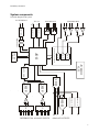
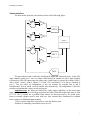
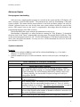
The three sensor ports have the structure shown in the following figure:
_
+5V
PGA
+
ADC0
_
+5V
PGA
+
MICRO
CONTROLLER
+5V
BUF
ADC1
BUF
DAC
The ports labeled with A and B have differential inputs and connected to two 16-bit ADC
input channels, while port C uses two single ended buffers for another two ADC input channels
referenced to GND. The input range for sensor ports A and B may be selected by software (20mV,
40mV, 80mV, 160mV, 320mV, 640mV, 1.2V and 2,56V) and fixed 2.5V for the two channels of
port C. The two ADCs are independent, so one can measure for example Port A and C
simultaneously (Port A and B can be measured only alternatively). The independent 12-bit DAC
provides a programmable voltage for all sensor ports.
Important note: the inputs are buffered by single supply amplifiers, so the safety input
range is limited to 0..5V (no overvoltage protection provided), while the usable input range is from
0V..3.5V. This is usually not a problem when sensors are driven/powered by the sensor ports,
however external voltages must be used with care. Also consider these limitations for common
mode voltages on differential input channels.
5V power and a single DAC output drives a pin for all three ports.
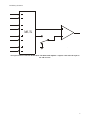
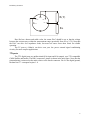
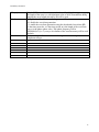
Example of connecting a thermistor to port A or B:
7