1
Preliminary document
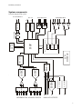
DAS1614SD internal structure and the central signal processing units
The data acquisition system has modular structure consisting of a power supply unit, a
backplane for euro-style cards and the plug-in cards. There are five cards in the unit by default:
• DSP card
• ADC card
• DAC and direct digital synthesizer (DDS) card
• SRAM memory card (1MWords)
• sensor and digital interface card.
The DAS1614SD data acquisition system uses three processors: a DSP for high speed data
acquisition and control, a microcontroller for controlling the sensor ports and another
microcontrooller for driving the LCD display.
The DSP has 80kbytes of on-chip memory for program and data storage. The acquired data
is temporarily stored here for asynchronous uploading to the host PC. It may also serve as a buffer
for arbitrary waveform generation. The current memory limit is 4kwords of data both for
acquisition and signal generation (may depend on software and external memory options).
The SRAM card serves as a buffer for long data acquisition processes by providing room
for 1Mwords of 16-bit data.
The DSP card has two independent UART ports: one for internal communications with the
plug-in cards and another for galvanically isolated communication with the host computer.
The DSP card manages a special 16-bit digital bus for intercard communications, two
independent synchronous serial buses and control signals such as address and I/O control.
The main units in the system are the following:
• 16-bit fixed point DSP
• eight channel 16-bit Σ∆ ADC (two ADCs, simultaneously sampling, two 4x1
overvoltage protected differential multiplexers)
• four independent 14-bit DACs
• two DDS signal generators (sampling clock and sine wave generation)
• isolated UART for host communication
• LCD display with a dedicated microcontroller
• Two 16-bit ADCs and a 12-bit DAC with a dedicated microcontroller for sensor
signal digitization
• Two high current voltage outputs driven by the 14-bit DACs
• Two independent SPDT relays
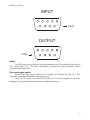
• 8-bit TTL input and 8-bit TTL output port
Analog inputs, A/D conversion
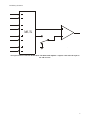
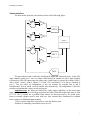
The eight analog input channels are organized as two four-channel blocks. Each block has a
four-channel differential multiplexer, a switch for selecting single ended operation (see figure
below). The inputs are overvoltage protected up to 20V below or above the supplies (-15V and
+15V if switched on). The input range is –10V to 10V. The multiplexer’s output is digitized by two
independent 16-bit Σ∆ ADCs, whose output is a 2’s complement 16-bit signed integer number.
4