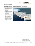
Download AMS Software Manual - Raymond RF Measurements Corp.
Transcript
AMS Version 4.0 User Manual AMS Antenna Measurement Software Modular Designed Software linked with TCP/IP ActiveX TM Graphing 2-D and 3-D Capability Testing Sequences controlled through Script Language Antenna Patterns in Polar, Rectangular, 3-D Standalone Equipment Drivers linked with TCP/IP Data management with ActiveX link to Microsoft Excel TM Report management with ActiveX Microsoft Word TM Available with optional OverThe-Air (OTA) CTIA Testing Requirements 3994 Elphin Maberly Rd PO Box 23072, Ottawa, On K2A 4E2 Tel: 1-613-298-3943 www.raymondrf.ca Copyright 2008, 2009, 2010, 2011, 2012 Raymond RF Measurements Corp. All rights reserved Page 1 AMS Version 4.0 User Manual Table of Contents 1. 2. Software Overview .................................................................................................................................. 4 1.1. Data Management........................................................................................................................... 4 1.2. Report Generation........................................................................................................................... 4 1.3. RF Test Equipment........................................................................................................................... 4 1.4. Test Equipment Setups.................................................................................................................... 4 1.5. Measurement .................................................................................................................................. 4 1.6. Graphing .......................................................................................................................................... 4 1.7. Recommended Minimum System Requirements ........................................................................... 5 1.8. AMS Features .................................................................................................................................. 5 Hardware Set Up ..................................................................................................................................... 6 2.1. AVS Block Diagram with Signal Generator and Spectrum Analyzer ................................................ 6 2.3. AVS Block Diagram with 2 Port VNA................................................................................................ 7 2.4. AVS Block Diagram with 4 Port VNA................................................................................................ 7 3. Software Installation ............................................................................................................................... 8 4. Software Layout .................................................................................................................................... 12 4.1. Start Window................................................................................................................................. 12 4.2. Measurement Tab ......................................................................................................................... 13 4.4. DUT Tab ......................................................................................................................................... 17 4.5. Test Parameters ............................................................................................................................ 18 4.6. Equipment Tab .............................................................................................................................. 20 4.7. Accessories Tab ............................................................................................................................. 22 4.8. Equipment Setups Tab................................................................................................................... 23 4.10. Positioner Devices Tab .............................................................................................................. 25 4.11. Reports Tab ............................................................................................................................... 26 4.12. Graphed Data Views Tab ........................................................................................................... 27 4.13. Communications Unit Driver ..................................................................................................... 28 4.14. Source Driver ............................................................................................................................. 29 3994 Elphin Maberly Rd PO Box 23072, Ottawa, On K2A 4E2 Tel: 1-613-298-3943 www.raymondrf.ca Copyright 2008, 2009, 2010, 2011, 2012 Raymond RF Measurements Corp. All rights reserved Page 2 AMS Version 4.0 User Manual 4.15. Receiver Driver .......................................................................................................................... 30 4.16. VNA Driver ................................................................................................................................. 31 4.17. Positioner Driver........................................................................................................................ 32 4.18. Excel Measurement Data Table................................................................................................. 33 4.19. Script Code................................................................................................................................. 34 5. Coordinate System ................................................................................................................................ 43 6. System Calibration................................................................................................................................. 45 6.1. Cable and Source Calibration with a SA or PM.............................................................................. 45 6.2. Switch Calibration with SA / PM and SG ....................................................................................... 54 6.3. Cable and Source Calibration with a VNA ..................................................................................... 57 6.4. Calibrated Measurement Antenna ................................................................................................ 64 6.5. Calibration of Switches with VNA .................................................................................................. 65 6.6. Range Reference Test .................................................................................................................... 65 6.7. Reference Antenna Pattern (Symmetry of Dipole) ....................................................................... 69 6.9. Ripple Test ..................................................................................................................................... 74 1.1.1. Figure 5-1 Great Circle Setup .................................................................................................43 1.1.2. Figure 5-2 Coordinate System ...............................................................................................44 1.1.3. Figure 5-3 Great Circle Coordinates .......................................................................................44 1.1.4. Figure 5-4 DUT Coordinates...................................................................................................44 1.1.5. Figure 5-5 SAM Coordinates ..................................................................................................44 1.1.6. Figure 5-6 DUT / SAM Coordinates ........................................................................................44 1.1.7. Figure 6-1 Theta Ripple Test ..................................................................................................75 1.1.8. Figure 6-2 Phi Ripple Test ......................................................................................................75 3994 Elphin Maberly Rd PO Box 23072, Ottawa, On K2A 4E2 Tel: 1-613-298-3943 www.raymondrf.ca Copyright 2008, 2009, 2010, 2011, 2012 Raymond RF Measurements Corp. All rights reserved Page 3 AMS Version 4.0 User Manual 1. Software Overview Raymond RF’s Antenna Measurement Software performs 2-D (polar/rectangular) and 3-D (spherical) antenna pattern measurements for passive antennas and active wireless mobile stations (cell phones). Insertion loss of passive devices is included as part of the calibration component. Data management and reporting of antenna properties such as half power beam-width, directivity, gain, radiation efficiency, total radiated power, and total isotropic sensitivity. AMS performs and reports all measurements required by the CTIA Over-the-Air Performance Test Plan. Insertion Loss / Gain measurements can be made on cables, preamps and attenuators as part of the calibration process. There are several sample videos of the AMS on our WEB site at: http://www.raymondrf.ca/products/products8.htm 1.1. Data Management AMS links to Microsoft Excel through ActiveX. Custom spreadsheets can be developed for data analysis. Standard spreadsheets are included and custom data analysis is very flexible. 1.2. Report Generation AMS links to Microsoft Word through ActiveX. Custom reports can be developed. Standard report templates are included and custom report generation is very flexible. 1.3. RF Test Equipment AMS controls popular Vector Network Analyzers, Spectrum Analyzers, Power Meters, Receivers, Signal Generators, Base Station Emulators, Amplifiers, RF switches and Attenuators. Control can be accomplished through Ethernet, GPIB, or RS232. Drivers are supplied with Raymond RF Positioners and custom drivers can be created for non-Raymond RF Antenna Positioners. 1.4. Test Equipment Setups Transmit and Receive equipment setups are easily set up and modified on a familiar hierarchy tree. Multiple Setups for each type of test can be saved for easy retrieval. 1.5. Measurement Once the DUT is in place and the appropriate information is entered, all Measurement Parameters are selected from the main Measurement Tab, and the measurement is run. The script file is run and measured (raw) data is stored to a text file and measured results are plotted in real time. Feedback from each device is also displayed in real time. Flexible design allows all Test Equipment and Positioners to optionally be controlled manually. 1.6. Graphing Advanced ActiveX graphing capabilities allow acquired data to be displayed in a variety of 2-D and 3-D formats. Data is linked to Excel through ActiveX, so it can be reviewed directly with Excel. 3994 Elphin Maberly Rd PO Box 23072, Ottawa, On K2A 4E2 Tel: 1-613-298-3943 www.raymondrf.ca Copyright 2008, 2009, 2010, 2011, 2012 Raymond RF Measurements Corp. All rights reserved Page 4 AMS Version 4.0 User Manual Data can be manipulated in Excel allowing users to develop their own data correlation / analysis algorithms. 1.7. Recommended Minimum System Requirements Pentium 4, 2500 MHz or compatible Microsoft XP / Vista/ 7 TM 4 GB RAM 50 GB free hard drive space CD-ROM Drive National Instruments GPIB card (Note: USB-A is not supported) 1.8. AMS Features Polar (Azimuth) Patterns: Single and Dual Polarization Tests, Scalar, Vector, Sensitivity Polar (Elevation) Patterns: Single and Dual Polarization Tests, Scalar, Vector, Sensitivity Spherical Patterns: Single and Dual Polarization Tests, Scalar, Vector, Sensitivity Insertion Loss / Gain testing of passive and active devices RF Equipment Drivers supplied: Agilent / Anritsu VNA, SA, SG, BSE, Amplifier, Attenuator, RF Switch. Custom RF Equipment Drivers Available Positioner Drivers supplied: Raymond RF Single Axis SD-455, and Dual Axis SD-455-3D Custom Positioner Drivers Available Word Report Templates Excel Data Templates Standard Test Scripts. Custom Test Scripts are available *ActiveX Link to *Excel and *Word Compatible with National Instruments GPIB-B and GPIB-H (USB-A not supported by National Instruments) Compatible with Ethernet and RS232 Upgrades for 2 years *Microsoft Excel , Microsoft Word and ActiveX are trademarks of Microsoft Corporation 3994 Elphin Maberly Rd PO Box 23072, Ottawa, On K2A 4E2 Tel: 1-613-298-3943 www.raymondrf.ca Copyright 2008, 2009, 2010, 2011, 2012 Raymond RF Measurements Corp. All rights reserved Page 5 AMS Version 4.0 User Manual 2. Hardware Set Up Set up the AVS System according to one of the following Block diagrams 2.1. AVS Block Diagram with Signal Generator and Spectrum Analyzer 3994 Elphin Maberly Rd PO Box 23072, Ottawa, On K2A 4E2 Tel: 1-613-298-3943 www.raymondrf.ca Copyright 2008, 2009, 2010, 2011, 2012 Raymond RF Measurements Corp. All rights reserved Page 6 AMS Version 4.0 User Manual 2.3. AVS Block Diagram with 2 Port VNA 2.4. AVS Block Diagram with 4 Port VNA 3994 Elphin Maberly Rd PO Box 23072, Ottawa, On K2A 4E2 Tel: 1-613-298-3943 www.raymondrf.ca Copyright 2008, 2009, 2010, 2011, 2012 Raymond RF Measurements Corp. All rights reserved Page 7 AMS Version 4.0 User Manual 3. Software Installation PC Requirements Free Disk Space: 50G Bytes RAM: 2GB CPU: 2.33 GHz or better CD-ROM or internet connection to download / install software Two USB-2 connections A 10/100 or 10/100/1000 Ethernet Connection. The TCP/IP address of this connection will need to be set before running AMS or any of the control drivers Microsoft XP / Vista / Windows 7, All 32 and 64 bit versions. Microsoft Excel 97 or newer, Microsoft Word 97 or newer. AMS has only been tested with 32 Bit versions of Excel and Word. At time of AMS Version 3.0 release, Microsoft notes that “Click to Run” versions of Excel and Word do not support all ActiveX clients at time of installation, and are therefore not compatible with AMS. Please refer to Microsoft instructions on how to remove “Click to Run” version and reinstall with “Classic” version. “Click to Run” versions, are down loaded directly from Microsoft and include a virtual drive “Q” or “R” drive on your PC. AMS: The AMS Host Computer requires a USB port to attach the National Instruments USB-GPIB Controller, and the USB-RS232 RF-Switch controller. A free 10, 10/100 or 10/100/1000 Ethernet Port to connect the Positioner Set the TCP/IP Address of the Ethernet connection on the host computer to 192.168.1.xxx, where xxx can be any number between 1 and 255 except 132 through 139 Server Port Number is set as 10000 by the AMS software Ensure that the host firewall does not block port 10000, 10001, 10010, 10020 and 10030. Depending on the version of Anti-Virus protection, this can normally be done through the automatic pop-ups, the first time AMS or a device is run. For computers with multiple Ethernet cards, ensure that the Ethernet Card attached to the positioner, is the first in the bindings list. Navigate to: ”Control Panel\Network and Internet\Network Connections”, select the Ethernet Card and press the “Alt” key, then select “Advanced” > “Advanced Settings”. Promote the Ethernet Card to the top, using the arrows, (or other method depending on version of window). Some versions of windows may require a reboot. Load the CD supplied by National Instruments, and install: National Instruments USB-GPIB Driver Software.. as per NI instructions and license. If your system utilizes an RF Switch, install the National Instruments NI-DAQmx Driver Software.. as per NI instructions and license. Load the CD supplied by Raymond RF (or download as per instructions from Raymond RF and run the following Setups as required, in the sequence listed below; Install all programs on the same hard drive 3994 Elphin Maberly Rd PO Box 23072, Ottawa, On K2A 4E2 Tel: 1-613-298-3943 www.raymondrf.ca Copyright 2008, 2009, 2010, 2011, 2012 Raymond RF Measurements Corp. All rights reserved Page 8 AMS Version 4.0 User Manual Upgrading Steps (IMPORTANT): For users whom are upgrading from prior Versions of AMS, or SpiraTable positioners, it is very important that the “Backup” utility is installed first. Both AMS and SpiraTable installations include default data files, which will overwrite some of your existing data during the installation of AMS. Exit AMS and all drivers prior to upgrading and software. Install the “Backup V4” utility and run a backup. Once the newer version(s) of AMS and / or SpiraTable-455-3D / SpiraTable are installed, use the restore feature of the “Backup” to restore your original data. Backup V4.0 .. Install in the default directory C:\AMS\Backup. Run the Backup prior to installing AMS V4.0 Convert V4.0 .. Install in the default directory C:\AMS\Convert. IMPORTANT! The convert utility is required to update files for use with Version 4.0. AMS.. install in the default directory C:\AMS If this is a new installation only, install the default data from “default data”, as follows: o Copy all of the files and directories from “data” to C:\Ams\data\ o Copy all of the files and directories from “Dbase” to C:\Ams\Dbase\. Note: This is a new Directory and will be created by the convert utility for users installing an upgrade. o Copy all of the files from “script” to C:\Ams\script\ o Copy all of the files from “templates” to C:\Ams\templates\ If this is an upgrade installation, once the new version of AMS 4.0 is installed, run Backup V 4.0 and select “Restore”. If this is an upgrade installation from a Version prior to AMS V4.01, Run the Convert utility prior to running AMS V4.xx Script Editor .. (OPTIONAL) Install in the default directory C:\Ams\Script The following drivers are all standalone programs and can be utilized to control each device independently from AMS. Each driver should be tested with the appropriate device to verify functionality prior to running AMS. The GPIB address of the device must be set to the default GPIB address for driver standalone execution. However, the GPIB address of any device and driver can be modified to any available GPIB address through the AMS program. o SpiraTable-455-3D.. install in default directory C:\AMS\SpiraTable-455-3D. This is the Control Driver for 3D Positioners o SpiraTable-455 .. install in default directory C:\AMS\SpiraTable. This is the Control Driver for 2D Positioners o HP8563E .. install in default directory C:\AMS\HP8563E. This is an Agilent Spectrum Analyzer Controller / Driver. The default GPIB address is 11. o AGPSA.. install in default directory C:\AMS\AGPSA. This is an Agilent PSA series Spectrum Analyzer Controller / Driver. The default GPIB address is 18. o E4405B .. install in default directory C:\AMS\E4405B. This is an Agilent Spectrum Analyzer Controller / Driver. The default GPIB address is 18. o 8647A .. install in default directory C:\AMS\8647A. This is an Agilent Signal Generator Controller / Driver. The default GPIB address is 19 o E8247C .. install in default directory C:\AMS\E8247C. This is an Agilent Signal Generator Controller / Driver . The default GPIB address is 19. o MG3692B .. install in default directory C:\AMS\MG3692B. This is an Anritsu Signal Generator Controller / Driver. The default GPIB address is 5. 3994 Elphin Maberly Rd PO Box 23072, Ottawa, On K2A 4E2 Tel: 1-613-298-3943 www.raymondrf.ca Copyright 2008, 2009, 2010, 2011, 2012 Raymond RF Measurements Corp. All rights reserved Page 9 AMS Version 4.0 User Manual o N5230A .. install in default directory C:\AMS\N5230A. This is an Agilent 2 port PNA (VNA) Controller / Driver. The default GPIB address is 16. o N5230C .. install in default directory C:\AMS\N5230C. This is an Agilent 4 port PNA (VNA) Controller / Driver. The default GPIB address is 16. o Accessories.. install in default directory C:\AMS\Accessories. These are the default RFSwitch, Remote Attenuator and Remote Amplifier Drivers Reference.. additional reference files including IVI drivers for 32 and 64 bit systems. Install the appropriate IVI driver for your system. If your system is Windows Vista, install the IVI Vista patch as well. SpiraTable Server .. (OPTIONAL) install in default directory C:\AMS\SpiraTable Server. This program and source code is provided for users who want to control the positioner with their own software. It is not required by the AMS. SpiraTable Client .. (OPTIONAL) install in default directory C:\AMS\SpiraTable Client. This program and source code is provided for users who want to control the positioner with their own software. It is not required by the AMS. SpiraTable (Spira-455): The SpiraTable Positioner, Spira-455, is controlled by SpiraTable.exe. It runs as a standalone application and is automatically launched from AMS or optionally by SpiraTable Server (see below). It can be launched and then controlled through SpiraTable Client as well, see below. It can be manually launched to control the positioner.. this may be useful during setups. To run SpiraTable in standalone mode, just run SpiraTable.exe without any parameters, from the start menu. Parameters: SpiraTable.exe PortType PortRate Address ServerPortNum; o i.e. SpiraTable.exe 2 10 192.168.1.129 10000 o PortType = 2 for TCP/IP o PortRate = 10 for 10BaseT; is compatible with any rate o Address of the Ethernet connection on the host computer is to be set as 192.168.1.xxx, where xxx can be any number between 1 and 255 except 132 through 139. Skip this step if it was done in AMS above. o ServerPortNum = 10000 Runs as both Client and Server at the same time TCP/IP Address is 192.168.1.xxx; This is the same address as AMS if the SpiraTable is connected to the same host computer Server Port is set as 10010, SpiraTable.exe is set to check for clients wanting to logon through this port. Client Port set by AMS or SpiraTable Server Theta Controller (on the positioner) TCP/IP Address 192.168.1.132 Port Number 10001 SpiraTable-455-3D: The SpiraTable-455-3D Positioner, SpiraTable-455-3D, is controlled by SpiraTable-3D.exe. It runs as a standalone application and is automatically launched from AMS or optionally by SpiraTable Server (see below). It can be launched and then controlled through SpiraTable Client as well, see below. 3994 Elphin Maberly Rd PO Box 23072, Ottawa, On K2A 4E2 Tel: 1-613-298-3943 www.raymondrf.ca Copyright 2008, 2009, 2010, 2011, 2012 Raymond RF Measurements Corp. All rights reserved Page 10 AMS Version 4.0 User Manual It can be manually launched to control the positioner.. this may be useful during setups. To run SpiraTable-455-3D in standalone mode, just run SpiraTable-455-3D.exe without any parameters, from the start menu. Parameters: SpiraTable-455-3D.exe PortType PortRate Address ServerPortNum; o i.e. SpiraTable.exe 2 10 192.168.1.129 10000 o PortType = 2 for TCP/IP o PortRate = 10 for 10BaseT; is compatible with any rate o Address of the Ethernet connection on the host computer is to be set as 192.168.1.xxx, where xxx can be any number between 1 and 255 except 132 through 139. Skip this step if it was done in AMS above. o ServerPortNum = 10000 Runs as Client and Server at the same time TCP/IP Address is 192.168.1.xxx; This is the same address as AMS if the SpiraTable is connected to the same host computer Server Port is 10020 Client Port set by AMS Theta Controller (on the positioner) TCP/IP Address 192.168.1.132 Port Number 10001 Phi Controller (on the positioner) TCP/IP Address 192.168.1.133 Port Number 10001 SpiraTable Client "Optional" Logs on to SpiraTable with Port Address 10010 This program and source code is provided for users who want to control the positioner with their own software. It is not required by the AMS. SpiraTable Server "Optional" SpiraTable logs on with Port Address 10000 This program and source code is provided for users who want to control the positioner with their own software. It is not required by the AMS. Note: SpiraTable Server and AMS cannot run at the same time on the same host computer as they would both compete to control the SpiraTable. Test each driver individually from the Windows Start Menu and verify that each device / instrument is functioning correctly. Please also review the videos which are located under the “Videos” directory. 3994 Elphin Maberly Rd PO Box 23072, Ottawa, On K2A 4E2 Tel: 1-613-298-3943 www.raymondrf.ca Copyright 2008, 2009, 2010, 2011, 2012 Raymond RF Measurements Corp. All rights reserved Page 11 AMS Version 4.0 User Manual 4. Software Layout 4.1. Start Window 4.1.1. Test New Devices 4.1.2. Load Saved Test 4.1.3. Calibrate System 4.1.4. User’s Manual – Opens this manual 4.1.5. Exit Window 3994 Elphin Maberly Rd PO Box 23072, Ottawa, On K2A 4E2 Tel: 1-613-298-3943 www.raymondrf.ca Copyright 2008, 2009, 2010, 2011, 2012 Raymond RF Measurements Corp. All rights reserved Page 12 AMS Version 4.0 User Manual 4.2. Measurement Tab This is the main tab for controlling test procedures and viewing test results. To access the Measurement Tab, Select>Measure from the main menu, then select the Measurement Tab. The Main menu also has: File>Open to open previously saved test setups. File>Save to save test setups File>Print to print results File>Exit to Exit AMS and close all open drivers and excel data sheets. Select>Measure to access the Measure, DUT and Test Parameters Tabs Select>Setups to access the Equipment, Accessories, Equipment Setups and Devices Tabs Select>Reports to access Reports and Views Tabs Options>Graph Options to toggle graph options on and off, on the Measurement Tab Macros> Run predefined and user defined Excel Macro Help>Help to access this document The Macros are processed from Excel i.e. “PAT-Macro” in the templates directory. AMS reads in the Macro Names and makes them available to the user. The user can review the Macros in Visual Basic from the Development Tab in Excel. If Excel doesn’t have the Development Tab, it will need 3994 Elphin Maberly Rd PO Box 23072, Ottawa, On K2A 4E2 Tel: 1-613-298-3943 www.raymondrf.ca Copyright 2008, 2009, 2010, 2011, 2012 Raymond RF Measurements Corp. All rights reserved Page 13 AMS Version 4.0 User Manual to be enabled. The user can make any changes to the Macros, as they are user definable. Additional Macros can also be added. 4.2.1. DUT Name, Range Length (cm), Test Date The DUT Name is selected from the DUT tab (see below) The Range length is the distance between the electrical centre of the Measurement antenna and the centre of the positioner. It is set by Raymond RF, however it may be adjusted by the user. Enter the test date as DD-MMM-YYYY 4.2.2. 3D Graph and controls The data can be displayed with the Y-axis as degrees, dB, mV/m or uV/m AMS reads the Excel data file and allows selection of graph type as Cartesian, Polar or 3D depending on available data The X-axis as Frequency, Azimuth, Elevation, Aux (polarization), depending on available data Discrete 2D cuts can be viewed, depending on available data The Frequency Ranges, or Discrete Frequency settings can be selected according to the Test type and Test Setup selected. The ActiveX 3D Graph can be rotated and zoomed interactively with the mouse. The controls surrounding the Graph are used to manipulate Graph settings and parameters. 4.2.3. Measurement Type, Setup, Parameters, Script Status Once the DUT is selected, The Measurement type, Test Setup Parameters, and Frequency Ranges are selected. If the data exists, Excel will open with the data file and the data is plotted on the AMS graph. If this is a new test, the graph will remain blank. During a test, the Script Status is displayed line by line as it is executed. 4.2.4. Operator, Data File Enter the name or initials of the test operator for reference purposes The Data file is set by AMS and is for reference purpose 4.2.5. Equipment Drivers Command Buttons for the Equipment drivers which are part of the selected test setup, are highlighted in Yellow. Prior to making a measurement each driver must be selected. Once the driver is active, its command button will change to green. If an Equipment Driver is not part of the test setup (Tx or Rx Chain), the command button will remain Grey, and not be accessible. AMS controls: Source, Receiver, VNA, Communications Unit Positioners: Azimuth, Elevation, 3rd Axis Remote Attenuators, Remote Amplifiers, Remote RF-Switches 3994 Elphin Maberly Rd PO Box 23072, Ottawa, On K2A 4E2 Tel: 1-613-298-3943 www.raymondrf.ca Copyright 2008, 2009, 2010, 2011, 2012 Raymond RF Measurements Corp. All rights reserved Page 14 AMS Version 4.0 User Manual 4.2.6. Start, Pause, Stop Once all of the appropriate drivers are activated, the Start, Pause and Stop buttons will change from Grey to Green, Yellow and Red, respectively. To start a test, select the Green Start Button. If data exists for the selected test, a pop-up menu will appear to request permission to overwrite data and repeat the measurement. 4.2.7. Display Excel (On/Off) 4.2.8. Graph Options Shown with the Macro CalcTRP 3994 Elphin Maberly Rd PO Box 23072, Ottawa, On K2A 4E2 Tel: 1-613-298-3943 www.raymondrf.ca Copyright 2008, 2009, 2010, 2011, 2012 Raymond RF Measurements Corp. All rights reserved Page 15 AMS Version 4.0 User Manual 4.2.9. Options: Pop Out Graph Shown in Wide Mode with Cable Insertion Loss Data 3994 Elphin Maberly Rd PO Box 23072, Ottawa, On K2A 4E2 Tel: 1-613-298-3943 www.raymondrf.ca Copyright 2008, 2009, 2010, 2011, 2012 Raymond RF Measurements Corp. All rights reserved Page 16 AMS Version 4.0 User Manual 4.3. DUT Tab To access the DUT Tab, Select>Measure from the main menu, then select the DUT Tab. 4.3.1. Cell Phones, Passive Devices, Antennas, Cables, Attenuators, Preamps Data for each DUT must be entered prior to making a test. Existing DUT information can be edited or a new DUT can be entered as required. Select the DUT type from the command buttons on the left. 4.3.2. DUT Name New / Delete To enter a new DUT, select New and enter the information as required. Unwanted DUTs can be deleted, and reentered at a later date if required. 4.3.3. DUT Information Enter as required for reference purpose. Enter the date as DD-MMM-YYY. Select the Data File Directory Button to select the Data Storage Directory. 3994 Elphin Maberly Rd PO Box 23072, Ottawa, On K2A 4E2 Tel: 1-613-298-3943 www.raymondrf.ca Copyright 2008, 2009, 2010, 2011, 2012 Raymond RF Measurements Corp. All rights reserved Page 17 AMS Version 4.0 User Manual 4.4. Test Parameters To access the Test Parameters Tab, Select>Measure from the main menu, then select the Test Parameters Tab. 4.4.1. Pattern, Radiated Power, Receiver Sensitivity, Range Reference, Ripple Test, Insertion Loss Test Setup parameters can be edited, or new Setups can be created as may be required for any of the tests Select the Test Type as per the command buttons on the left. Select the appropriate Setup or select New. Edit the information as required. 4.4.2. New / Delete Select New or Delete as required. 4.4.3. DUT Table 3994 Elphin Maberly Rd PO Box 23072, Ottawa, On K2A 4E2 Tel: 1-613-298-3943 www.raymondrf.ca Copyright 2008, 2009, 2010, 2011, 2012 Raymond RF Measurements Corp. All rights reserved Page 18 AMS Version 4.0 User Manual Enter any parameters in the DUT table. Up to 12 setups can be entered. Name, Mount and Antenna are for reference purpose only. The Tx, Ty and Tz are the offsets from the centre of the positioner, in cm. The coordinate system is described in section 4. 4.4.4. Test Script File Name Select the Script file Button to select any available script file. The script file is in text format and can be edited as may be required. 4.4.5. Equipment Setup Select the Equipment Setup Button to select any available Equipment Setups. A popup window will appear with all available Equipment Setups. Equipment Setup (chains) are discussed below. 4.4.6. Positioner Parameters Edit as required. 4.4.7. Frequency Parameters Edit as required. 3994 Elphin Maberly Rd PO Box 23072, Ottawa, On K2A 4E2 Tel: 1-613-298-3943 www.raymondrf.ca Copyright 2008, 2009, 2010, 2011, 2012 Raymond RF Measurements Corp. All rights reserved Page 19 AMS Version 4.0 User Manual 4.5. Equipment Tab To access the Equipment Tab, Select>Setups from the main menu, then select the Equipment Tab. 4.5.1. Source, Receiver, VNA, Communications Unit, Amplifier, RF Switch, Attenuator Equipment Drivers can be edited, or new Drivers can be created as may be required for any of the tests Select the Equipment Type as per the command buttons on the left. Select the appropriate piece of Equipment or select New. Edit the information as required. 4.5.2. New / Delete Select as required. 4.5.3. Equipment Information Enter all of the information as required. Select the Calibration File Button to select the appropriate directory which contains the calibration data for the equipment. 3994 Elphin Maberly Rd PO Box 23072, Ottawa, On K2A 4E2 Tel: 1-613-298-3943 www.raymondrf.ca Copyright 2008, 2009, 2010, 2011, 2012 Raymond RF Measurements Corp. All rights reserved Page 20 AMS Version 4.0 User Manual Select the Device Driver Button 4.5.4. to select the appropriate driver for the equipment. Equipment Parameters Enter information as required for reference purposes 3994 Elphin Maberly Rd PO Box 23072, Ottawa, On K2A 4E2 Tel: 1-613-298-3943 www.raymondrf.ca Copyright 2008, 2009, 2010, 2011, 2012 Raymond RF Measurements Corp. All rights reserved Page 21 AMS Version 4.0 User Manual 4.6. Accessories Tab To access the Accessories Tab, Select>Setups from the main menu, then select the Accessories Tab. 4.6.1. Antenna, Cable, Pre Amp, Attenuator Accessory Equipment which do not require drivers can be edited, or new accessories can be created as may be required for any of the tests Select the Accessory Type as per the command buttons on the left. Select the appropriate piece of Equipment or select New. Edit the information as required. 4.6.2. New / Delete Select as required 4.6.3. Accessory Information Enter all of the information as required. Select the Calibration File Button to select the appropriate directory which contains the calibration data for the equipment. 3994 Elphin Maberly Rd PO Box 23072, Ottawa, On K2A 4E2 Tel: 1-613-298-3943 www.raymondrf.ca Copyright 2008, 2009, 2010, 2011, 2012 Raymond RF Measurements Corp. All rights reserved Page 22 AMS Version 4.0 User Manual 4.7. Equipment Setups Tab To access the Equipment Setups Tab, Select>Setups from the main menu, then select the Equipment Setups Tab. All of the devices in the Tx and Rx chains is identified in this Tab. 4.7.1. Pattern, Radiated Power, Receiver Sensitivity, Range Reference, Ripple Test, Insertion Loss Select the appropriate Test Setup Type Command Button on the left. Default Chain Setups will appear in the Chain list. Select the appropriate chain or select New or Delete as required. 4.7.2. New / Delete Chain Select as required. 4.7.3. Azimuth, Elevation, Auxiliary Devices Select as required. Note that if the SpiraTable-455-3D is selected as the azimuth device, there is no need to select an elevation device 3994 Elphin Maberly Rd PO Box 23072, Ottawa, On K2A 4E2 Tel: 1-613-298-3943 www.raymondrf.ca Copyright 2008, 2009, 2010, 2011, 2012 Raymond RF Measurements Corp. All rights reserved Page 23 AMS Version 4.0 User Manual 4.7.4. Transmit Chain List Select New / Delete Tx Equipment as required. A pop-up menu will appear with all available Equipment and Accessories. Select as required. Items in the chain can be dragged with the mouse into position as required. Select Save Tx Chain when complete. A special case is for the VNA port 2, as this is the Transmit Port for calibration purpose, and does not have a driver. VNA-P2 is found in the accessory cables. The VNA driver is entered in the RX chain below. 4.7.5. Receive Chain List Select New / Delete Rx Equipment as required. A pop-up menu will appear with all available Equipment and Accessories. Select as required. Items in the chain can be dragged with the mouse into position as required. Select Save Rx Chain when complete. 4.7.6. Remote RF Switches AMS supports up to 3 Remote RF Switches. These switches can be assigned in both the Tx and Rx chain. The following rules apply to the use of Switches: 1. Switches are numbered 1 through 3 starting with their appearance in the Tx chain first, then as they appear in the Rx chain. 2. Each switch can have a maximum of 3 ports, A, B and optional C. 3. Each switch must utilize a minimum of ports A and B 4. Switch ports for Switch1 are labeled Switch1A, Switch1B and Switch1C 5. Switch ports for Switch2 are labeled Switch2A, Switch2B and Switch2C 6. Switch ports for Switch3 are labeled Switch3A, Switch3B and Switch3C 7. The second switch in a chain must be attached directly to one of the ports of the first switch. Please see Tx Switch example, below. Tx Switch Example 8. A third switch can either be attached directly to one of the ports on the first switch or one of the ports on the second switch. 9. All sub components such as cables, attenuators, antennas, VNA ports etc. must start after the switch port 10. The purpose of listing components after the appropriate switch port is to ensure that AMS selects the correct calibration files for each component when calculating the overall insertion loss / gain of the active chain. 3994 Elphin Maberly Rd PO Box 23072, Ottawa, On K2A 4E2 Tel: 1-613-298-3943 www.raymondrf.ca Copyright 2008, 2009, 2010, 2011, 2012 Raymond RF Measurements Corp. All rights reserved Page 24 AMS Version 4.0 User Manual 4.8. Positioner Devices Tab To access the Devices Tab, Select>Setups from the main menu, then select the Devices Tab. All of the positioning devices are identified in this Tab. 4.8.1. Positioner Select Positioner Command Button on the Left. A list of defined positioners will appear in the list. 4.8.2. New / Delete Select as required. 4.8.3. Positioner Information Enter the positioner name and select the type as 1- Axis Az (theta), 2-Axis Az & El (theta & phi), 3-Axial Aux axis. Only 2 positioners can be activated at one time. Either a single axis Az and an Axial Aux, or a 2-Axis Az & El and an Axial Aux. 4.8.4. Positioner Parameters 3994 Elphin Maberly Rd PO Box 23072, Ottawa, On K2A 4E2 Tel: 1-613-298-3943 www.raymondrf.ca Copyright 2008, 2009, 2010, 2011, 2012 Raymond RF Measurements Corp. All rights reserved Page 25 AMS Version 4.0 User Manual Enter information as required for reference purpose. Select the Device Driver Button to select the appropriate driver for the positioner. Other parameters are discussed in Section 3 above. 4.9. Reports Tab 4.9.1. Pattern, Radiated Power, Receiver Sensitivity, Range Reference, Ripple Test, Insertion Loss 4.9.2. Report Name, New / Delete 3994 Elphin Maberly Rd PO Box 23072, Ottawa, On K2A 4E2 Tel: 1-613-298-3943 www.raymondrf.ca Copyright 2008, 2009, 2010, 2011, 2012 Raymond RF Measurements Corp. All rights reserved Page 26 AMS Version 4.0 User Manual 4.10. Graphed Data Views Tab The Views tab allows the user to view and compare results for different parameters. 3994 Elphin Maberly Rd PO Box 23072, Ottawa, On K2A 4E2 Tel: 1-613-298-3943 www.raymondrf.ca Copyright 2008, 2009, 2010, 2011, 2012 Raymond RF Measurements Corp. All rights reserved Page 27 AMS Version 4.0 User Manual 4.11. Communications Unit Driver 3994 Elphin Maberly Rd PO Box 23072, Ottawa, On K2A 4E2 Tel: 1-613-298-3943 www.raymondrf.ca Copyright 2008, 2009, 2010, 2011, 2012 Raymond RF Measurements Corp. All rights reserved Page 28 AMS Version 4.0 User Manual 4.12. Source Driver 3994 Elphin Maberly Rd PO Box 23072, Ottawa, On K2A 4E2 Tel: 1-613-298-3943 www.raymondrf.ca Copyright 2008, 2009, 2010, 2011, 2012 Raymond RF Measurements Corp. All rights reserved Page 29 AMS Version 4.0 User Manual 4.13. Receiver Driver 3994 Elphin Maberly Rd PO Box 23072, Ottawa, On K2A 4E2 Tel: 1-613-298-3943 www.raymondrf.ca Copyright 2008, 2009, 2010, 2011, 2012 Raymond RF Measurements Corp. All rights reserved Page 30 AMS Version 4.0 User Manual 4.14. VNA Driver 3994 Elphin Maberly Rd PO Box 23072, Ottawa, On K2A 4E2 Tel: 1-613-298-3943 www.raymondrf.ca Copyright 2008, 2009, 2010, 2011, 2012 Raymond RF Measurements Corp. All rights reserved Page 31 AMS Version 4.0 User Manual 4.15. Positioner Driver 3994 Elphin Maberly Rd PO Box 23072, Ottawa, On K2A 4E2 Tel: 1-613-298-3943 www.raymondrf.ca Copyright 2008, 2009, 2010, 2011, 2012 Raymond RF Measurements Corp. All rights reserved Page 32 AMS Version 4.0 User Manual 4.16. Excel Measurement Data Table 3994 Elphin Maberly Rd PO Box 23072, Ottawa, On K2A 4E2 Tel: 1-613-298-3943 www.raymondrf.ca Copyright 2008, 2009, 2010, 2011, 2012 Raymond RF Measurements Corp. All rights reserved Page 33 AMS Version 4.0 User Manual 4.17. Script Code AMS uses a customizable proprietary script code, which is provided for all standard measurements. Raymond RF can also provide custom script code, if required. Instructions for developing custom script code are provided for users wishing to develop their own custom script code. Please note that all parameters are separated with a space and not commas, as the spaces are used for tokens when parsing. Script code can be created or edited with any text editor such as MS NotePad or with the included Script editor, which also includes error checking. 4.17.1. Sample Script Code for “RippleTest.txt” #Ripple Script File real Az real El real Tx real Freq 3994 Elphin Maberly Rd PO Box 23072, Ottawa, On K2A 4E2 Tel: 1-613-298-3943 www.raymondrf.ca Copyright 2008, 2009, 2010, 2011, 2012 Raymond RF Measurements Corp. All rights reserved Page 34 AMS Version 4.0 User Manual real Power real Span real PkAmp real pkFreq real Phase label LOOPAZ label LOOPEL label LOOPFREQ label SAVE label END Phase = 0.0 Positioner1 Init Switch1 Init Source Init Freq = AMS GetFirstFreq Source SetFreq Freq Power = 0.0 Source SetPower Power Receiver Init Switch1 A Tx = 0.0 El = AMS_ElStart - AMS_ElStep LOOPEL El = El + AMS_ElStep if El > AMS_ElStop goto END Positioner1 MoveEl El Az = AMS_AzStart - AMS_AzStep LOOPAZ Freq = AMS GetFirstFreq Az = Az + AMS_AzStep if Az > AMS_AzStop goto LOOPEL Positioner1 MoveAz Az LOOPFREQ if Freq == 0.0 goto LOOPAZ Source SetFreq Freq Receiver SetFreq Freq Span = Freq * 0.1 Receiver SetSpan Span Switch1 A Tx = 0 Receiver Sweep PkAmp = Receiver GetPeakAmp 3994 Elphin Maberly Rd PO Box 23072, Ottawa, On K2A 4E2 Tel: 1-613-298-3943 www.raymondrf.ca Copyright 2008, 2009, 2010, 2011, 2012 Raymond RF Measurements Corp. All rights reserved Page 35 AMS Version 4.0 User Manual pkFreq = Receiver GetPeakFreq SaveData Freq Power Az El Tx PkAmp Phase Switch1 B Tx = 90 Receiver Sweep PkAmp = Receiver GetPeakAmp pkFreq = Receiver GetPeakFreq SaveData Freq Power Az El Tx PkAmp Phase Freq = AMS GetNextFreq goto LOOPFREQ END El = AMS_ElStart Az = AMS_AzStart Positioner1 MoveAz Az Positioner1 MoveEl El Popup "Test Complete" 4.17.2. Script Text Files Script code files are located in the directory C:\AMS\Script\. Script code files may have a maximum of 199 lines. Nomenclature: “real” refers to a declared variable with double precision “int” refers to a declared integer “AMS_real” refers to any of pre declared AMS real variables listed below “AMS_int” refers to any of pre declared AMS integer variables listed below “real value” refers to any real number 4.17.3. Comments Script code lines starting with # are comments and are ignored 4.17.4. Declarable Variables Variables can be declared as real or int. Variables must be declared at the beginning of the script. A variable name must not duplicate an AMS variable, as described below. 4.17.5. Labels Labels are used for “goto” and “if goto” Statements 4.17.6. Device functions Device functions are used to control and communicate with the device drivers. Control Device functions have the format of “Device Par1 Par2 Par3…”. 3994 Elphin Maberly Rd PO Box 23072, Ottawa, On K2A 4E2 Tel: 1-613-298-3943 www.raymondrf.ca Copyright 2008, 2009, 2010, 2011, 2012 Raymond RF Measurements Corp. All rights reserved Page 36 AMS Version 4.0 User Manual Communication device functions retrieve data from the device, and have the format of “real = Device Par1 Par Par3 …”. Positioner 1 and 3 Device Functions: (Positioner2 is the second axes of Positioner1) Positioner1 Init Positioner1 MoveAz real (where real is between 0.0 and 360.0) Positioner1 MoveEl real (where real is between 0.0 and 360.0) Positioner1 Stop Source Source Init Source SetFreq real (AMS_Freq is updated to real MHz value) Source SetPower real (AMS_Power is updated to real dBm value) Receiver Receiver Init Receiver SetFreq real (AMS_Freq is updated to real MHz value) Receiver SetSpan real (AMS_Span is updated to real MHz value) Receiver SetBandWidth real (AMS_BandWidth is updated to real MHz value) Receiver SetPeakHold real (AMS_PeakHold is updated to int value, 0 = off, 1= on) Receiver Sweep Receiver SaveTrace (Saves trace to C:\AMS\Data\Trace.csv, see PlotTrace below) real = Receiver GetPeakFreq real = Receiver GetPeakAmp VNA VNA Init VNA SetFreq real (AMS_Freq is updated to real MHz value) VNA SetPower real (AMS_Power is updated to real dBm value) VNA SetSpan real (AMS_Span is updated to real MHz value) VNA SetBandWidth real (AMS_BandWidth is updated to real MHz value) VNA SetPeakHold real (AMS_PeakHold is updated to int value, 0 = off, 1= on) VNA Sweep VNA SaveTraceS11 (Saves trace to C:\AMS\Data\Trace.csv, see PlotTrace below) real = VNA GetPeakFreqS11 real = VNA GetPeakAmpS11 3994 Elphin Maberly Rd PO Box 23072, Ottawa, On K2A 4E2 Tel: 1-613-298-3943 www.raymondrf.ca Copyright 2008, 2009, 2010, 2011, 2012 Raymond RF Measurements Corp. All rights reserved Page 37 AMS Version 4.0 User Manual real = VNA GetCFreqAmpS11 real = VNA GetCPhaseS11 VNA SaveTraceS21 (Saves trace to C:\AMS\Data\Trace.csv, see PlotTrace below) real = VNA GetPeakFreqS21 real = VNA GetPeakAmpS21 real = VNA GetCFreqAmpS21 real = VNA GetCPhaseS21 VNA SaveTraceS31 (Saves trace to C:\AMS\Data\Trace.csv, see PlotTrace below) real = VNA GetPeakFreqS31 real = VNA GetPeakAmpS31 real = VNA GetCFreqAmpS31 real = VNA GetCPhaseS31 VNA SaveTraceS12 (Saves trace to C:\AMS\Data\Trace.csv, see PlotTrace below) real = VNA GetPeakFreqS12 real = VNA GetPeakAmpS12 real = VNA GetCFreqAmpS12 real = VNA GetCPhaseS12 VNA SaveTraceS13 (Saves trace to C:\AMS\Data\Trace.csv, see PlotTrace below) real = VNA GetPeakFreqS13 real = VNA GetPeakAmpS13 real = VNA GetCFreqAmpS13 real = VNA GetCPhaseS13 Comms Comms String real = Comms String int = Comms String String varies as required with a maximum of 9 words. Spaces are treated as tokens to parse the string. Each word may be a maximum of 24 characters. Amplifier1 Amplifier1 Init Amplifier1 SetGain real (AMS_Amp1_Gain is updated to real dBm value) Real = Amplifier1 GetGain Amplifier2 3994 Elphin Maberly Rd PO Box 23072, Ottawa, On K2A 4E2 Tel: 1-613-298-3943 www.raymondrf.ca Copyright 2008, 2009, 2010, 2011, 2012 Raymond RF Measurements Corp. All rights reserved Page 38 AMS Version 4.0 User Manual Amplifier2 Init Amplifier2 SetGain real (AMS_Amp2_Gain is updated to real dBm value) Real = Amplifier2 GetGain Attenuator1 Attenuator1 Init Attenuator1 SetGain real (AMS_Att1_Gain is updated to real dBm value) Real = Attenuator1 GetGain Attenuator2 Attenuator2 Init Attenuator2 SetGain real (AMS_Att2_Gain is updated to real dBm value) Real = Attenuator2 GetGain Switch1 Switch1 Init Switch1 A (AMS_Switch1 is updated to 1, used for calculating chain number) Switch1 B (AMS_Switch1 is updated to 2, used for calculating chain number) Switch1 C (AMS_Switch1 is updated to 3, used for calculating chain number) Switch2 Switch2 Init Switch2 A (AMS_Switch2 is updated to 1, used for calculating chain number) Switch2 B (AMS_Switch2 is updated to 2, used for calculating chain number) Switch2 C (AMS_Switch2 is updated to 3, used for calculating chain number) Switch3 Switch3 Init Switch3 A (AMS_Switch3 is updated to 1, used for calculating chain number) Switch3 B (AMS_Switch3 is updated to 2, used for calculating chain number) Switch3 C (AMS_Switch3 is updated to 3, used for calculating chain number) 3994 Elphin Maberly Rd PO Box 23072, Ottawa, On K2A 4E2 Tel: 1-613-298-3943 www.raymondrf.ca Copyright 2008, 2009, 2010, 2011, 2012 Raymond RF Measurements Corp. All rights reserved Page 39 AMS Version 4.0 User Manual AMS real = AMS GetFirstFreq (this is the first frequency from the frequency list) real = AMS GetNextFreq 4.17.7. Predefined AMS_reals AMS reals are initialized from the Test Setup Tab at the start of the script. They can only be referenced and not changed during script execution. AMS_AzStart AMS_AzStop AMS_AzStep AMS_AzRPM AMS_AzAcc AMS_AzDwell AMS_ElStart AMS_ElStop AMS_ElStep AMS_ElRPM AMS_ElAcc AMS_ElDwell AMS_AxStart AMS_AxStop AMS_AxStep AMS_AxRPM AMS_AxAcc AMS_AxDwell AMS_FreqStart AMS_FreqStop AMS_FreqStep AMS_GrossPowerStep AMS_FinePowerStep AMS_MaxBER AMS_MaxPower AMS_Phase 4.17.8. Process Operators (po) “=” Equals “+” Plus “-“ Minus “/” Divide by “*” Multiply Allowable uses of Operators 3994 Elphin Maberly Rd PO Box 23072, Ottawa, On K2A 4E2 Tel: 1-613-298-3943 www.raymondrf.ca Copyright 2008, 2009, 2010, 2011, 2012 Raymond RF Measurements Corp. All rights reserved Page 40 AMS Version 4.0 User Manual o o o o o o o o o o o o o o real = real value real = real real = AMS_real real = real op real value, i.e Span = Freq * 0.001 real = real op real, i.e. Span = Freq + Step real = real op AMS_real real = AMS_real op AMS_real Int = int value int = int int = AMS_int int = int op int value, i.e Index = Index + 1 int = int op int, i.e. Span = Freq + Step int = int op AMS_int int = AMS_int op AMS_int 4.17.9. Process Comparators (pc) “==” Equals “<=” Less than or equal to “>=” Greater than or equal to “!=” Not equal to “<” Less than “>” Greater than 4.17.10. If goto if real pc real goto lable if int pc int goto lable if real pc AMS_real goto lable if int pc AMS_int goto lable if real pc real value goto lable if int pc int value goto lable 4.17.11. goto goto lable 4.17.12. SaveData SaveData is used to store measured data into the Excel Data Sheet SaveData freq power Az El Aux PkAmp Phase Spare1 Spare2 All parameters are real Spare1 and Spare2 are optional 4.17.13. PlotTrace PlotTrace is used to save the trace data into the Excel Data Sheet 3994 Elphin Maberly Rd PO Box 23072, Ottawa, On K2A 4E2 Tel: 1-613-298-3943 www.raymondrf.ca Copyright 2008, 2009, 2010, 2011, 2012 Raymond RF Measurements Corp. All rights reserved Page 41 AMS Version 4.0 User Manual 4.17.14. There are no parameters required Popup Popup Any message up to 9 words. Spaces are treated as tokens to parse the string. Each word may be a maximum of 24 characters. 3994 Elphin Maberly Rd PO Box 23072, Ottawa, On K2A 4E2 Tel: 1-613-298-3943 www.raymondrf.ca Copyright 2008, 2009, 2010, 2011, 2012 Raymond RF Measurements Corp. All rights reserved Page 42 AMS Version 4.0 User Manual 5. Coordinate System The coordinate system is as described by the CTIA Test Plan for the "Great Circle" Figure 5-1 Great Circle Setup 3994 Elphin Maberly Rd PO Box 23072, Ottawa, On K2A 4E2 Tel: 1-613-298-3943 www.raymondrf.ca Copyright 2008, 2009, 2010, 2011, 2012 Raymond RF Measurements Corp. All rights reserved Page 43 AMS Version 4.0 User Manual Figure 5-3 Great Circle Coordinates Figure 5-2 Coordinate System Figure 5-5 SAM Coordinates Figure 5-4 DUT Coordinates Figure 5-6 DUT / SAM Coordinates 3994 Elphin Maberly Rd PO Box 23072, Ottawa, On K2A 4E2 Tel: 1-613-298-3943 www.raymondrf.ca Copyright 2008, 2009, 2010, 2011, 2012 Raymond RF Measurements Corp. All rights reserved Page 44 AMS Version 4.0 User Manual 6. System Calibration The AVS system relies on the Receiver (Power Meter / Network Analyzer / Spectrum Analyzer) and the measurement antenna being in calibration. Once the entire system is calibrated, routine calibration checks can be performed utilizing a reference antenna such as a standard gain horn or sleeve dipole as may be required. The Dual Polarized Measurement Antenna was installed with the system and is called "AVS700-H" and “AVS700-V”. The calibrated gain values for this antenna were entered at Raymond RF. This antenna should be calibrated bi-annually to ensure system accuracy. Instructions for entering calibration data for the Measurement Antenna are included in section 6.4 below. All of the cables which were shipped with the AVS System were calibrated at Raymond RF. However the user can recalibrate the cables, or add new cables as described in section 6.1 below. Accuracy of the system was validated by Raymond RF utilizing the Ripple Test Method. The entire system was validated by Raymond RF using a calibrated reference antenna to establish the Range Reference. However the user can validate the system as described in section 6.6 below. The complete validation process is: 1. 2. 3. 4. 5. 6. Calibration of Cables and Source Enter Measurement Antenna Gain (dBi) Reference Antenna Symmetry Test Range Reference Ripple Test Optional for CTIA type measurements: Calculation of Uncertainties, refer to CTIA test procedures. 6.1. Cable and Source Calibration with a SA or PM The Receiver (Power Meter / Spectrum Analyzer) must be in calibration to proceed. The following instructions are for a calibration range of 100MHz (start) to 20000MHz (stop) in 100MHz steps. The start, stop and step frequencies can be change to match the SG and SA ranges. Remove all of the cables from the AVS system. Ensure that cables are labeled Cable-001, Cable-002, … Cablexxx . Step 1 Measure combined Gain of SG and Cable-001 1. Install Cable 001 between SG and SA 2. Run AMS 3994 Elphin Maberly Rd PO Box 23072, Ottawa, On K2A 4E2 Tel: 1-613-298-3943 www.raymondrf.ca Copyright 2008, 2009, 2010, 2011, 2012 Raymond RF Measurements Corp. All rights reserved Page 45 AMS Version 4.0 User Manual 3. From the Introduction Panel, Select "Calibrate System" 4. Select Devices Tab 5. Select "Positioner" 6. Select Positioner "Spira-455-3D" or "Spira-455" (for 2D system) from list 7. Edit information as required: a. Positioner Name: Spira-455-3D or Spira-455 b. Type: 2-Axis Az & El or 1-Axis Az c. Model: Spira-455-3D or Spira-455 d. Serial Number: xxxx e. Calibration Date: DD-MMM-YYYY f. Device Driver: Select the Device Driver Button the positioner. g. Port Type: TCP/IP h. Port Address: 10000 i. Port Rate: 100 j. Maximum RPM: 6 k. Minimum RPM 0.1 l. Maximum Acc: 2 m. Minimum Acc: 1 n. Resolution (deg): 0.01 o. Maximum Temp (C): 48 p. Maximum Amperage: 6 8. Select the Equipment Tab to select the appropriate driver for 9. Select "Source" 10. Select the source from the list. If the appropriate source does not exist, ensure that the appropriate driver was installed as per section 3 above. Then select “New” and name it with the model name, such as “E8247C-Uncal”. 11. Edit the Source info: a. Manufacturer: i.e. “Agilent” b. Type: Select “Signal Generator” from the list c. Model as required d. Serial Number as required e. VERY IMPORTANT! Set Calibration File Name to "NULL", without the “”, type over any exiting information. f. Select the Device Driver Button the equipment to navigate and select the appropriate driver for 3994 Elphin Maberly Rd PO Box 23072, Ottawa, On K2A 4E2 Tel: 1-613-298-3943 www.raymondrf.ca Copyright 2008, 2009, 2010, 2011, 2012 Raymond RF Measurements Corp. All rights reserved Page 46 AMS Version 4.0 User Manual g. h. i. j. k. l. m. Port Type: Select as “GPIB” Port / Address: Typically 19 for an SG, edit as required. Port Rate: 100 Min Freq. (MHz): as per SG specs Max Freq. (MHz): as per SG specs Min Power (dBm): as per SG specs Max Power (dBm): as per SG specs 12. Select "Receiver" if using a Spectrum Analyzer, 13. Select the Spectrum Analyzer from the list. If the appropriate SA does not exist, ensure that the appropriate driver was installed as per section 3 above. Then select “New” and name it with the model name, such as “8563EC”. 14. Edit the Source info: a. Manufacturer: i.e. “Agilent” b. Type: Select “Spectrum Analyzer” from the list c. Model as required d. Serial Number as required e. VERY IMPORTANT! Set Calibration File Name to "NULL", without the quotation marks f. Select the Device Driver Button to navigate and select the appropriate driver for the equipment g. Port Type: Select as “GPIB” h. Port / Address: Typically 11 for an SA, edit as required. i. Port Rate: 100 j. Min Freq. (MHz): as per SA specs k. Max Freq. (MHz): as per SA specs l. Min Power (dBm): as per SA specs m. Max Power (dBm): as per SA specs 15. Select "Equipment Setups" Tab 16. 17. 18. 19. 20. 21. 22. 23. 24. Select Test Type Setup: "Insertion Loss" Select "ILC-Cal1", from Insertion Loss Chains List Enter “NULL” in Azimuth, Elevation and Auxiliary Device fields Select New Tx Chain Item, The Select Window will popup Select Source from the Select Popup Window Select the SG-Uncal from the list Exit popup Window Ensure that the SG-Uncal is the only item on the chain list, delete any other items. Save Tx Chain 3994 Elphin Maberly Rd PO Box 23072, Ottawa, On K2A 4E2 Tel: 1-613-298-3943 www.raymondrf.ca Copyright 2008, 2009, 2010, 2011, 2012 Raymond RF Measurements Corp. All rights reserved Page 47 AMS Version 4.0 User Manual 25. 26. 27. 28. 29. 30. Select New Rx Chain Item, The Select Window will popup Select the SA / Receiver from the Select Popup Window Ensure that the SA / Receiver is the only item on the chain list, delete any other items. Select the SA from the list Exit popup Window Save Rx Chain, The Panel should be as follows 31. 32. 33. 34. Select Equipment Tab Select Source Select the SG-Uncal from the sources VERY IMPORTANT! If not already completed in step 14.e above, Delete any text in the Calibration File field and enter "NULL" (without the quotation “” marks). From Main Menu Bar, Select > Measure Select Test Parameters Tab Select Test Type: "Insertion Loss" Select "ILS-Cal1", from the Insertion Loss Setups List Set the Start, Stop and Step as 700, 10000 and 100 and select MHz. Ensure that all values are within the test equipment range. Select the DUT Tab 35. 36. 37. 38. 39. 40. 41. 42. 43. 44. Select "Cable" Equipment Type Select "Cable-001-Cal1" Edit Information as required Select Data File Directory "...", in popup window, navigate to "Cable-001-Cal1", select “Done” . Ensure that the directory "Cable-001" was not selected, as it will be utilized further 3994 Elphin Maberly Rd PO Box 23072, Ottawa, On K2A 4E2 Tel: 1-613-298-3943 www.raymondrf.ca Copyright 2008, 2009, 2010, 2011, 2012 Raymond RF Measurements Corp. All rights reserved Page 48 AMS Version 4.0 User Manual 45. 46. 47. 48. 49. 50. 51. 52. 53. 54. 55. 56. 57. 58. 59. 60. 61. 62. on. Enter the same frequency values as per the Start and Stop, above. Enter min / max power values as per the SA / Receiver range. Select Measurement Tab Enter Date "DD-MMM_YYYY" Enter Operator Select Measurement Type: "Insertion Loss" Select Setup "ILS-Cal1" Select Parameters "STD" Select Frequency "700-10000 MHz", are as per the appropriate range above. If the Display Excel Button is “On”, Excel will open up in the back ground. NOTE: AMS controls Excel through ActiveX calls; Never make changes to the excel file while measurements are being taken as the data and the file will most likely be corrupted From Main Menu Bar, Select File, Save, select ILS-Cal1, OK, Yes Overwrite Select the yellow "Source".. Source driver will open and the button will turn to green. Note that any Equipment driver may be hidden by either selecting "Exit Window" on the driver, or by selecting the associated green driver button on the AMS Measurement tab and then selecting "Hide". To view the driver again, select the green driver button and then select "Hide". Select "Receiver".. Receiver driver will open and the button will turn to green Select the AMS Application Select "Start" to start measurement, if prompted to repeat measurement, select “Yes”. Popup will appear once the measurement is complete Results are graphed Select Green "Source" button, Select "Close", SG driver will close Select Green "Receiver" button, Select "Close", SA driver will close Step2 Measure combined gain of SG, Cable-001 and Cable-002. The Gain from Step 1 will be subtracted from this and the result will be the Gain / Insertion loss of Cable-002. 63. Install Cable-002 between Cable-001 and SA, so it is: SG, Cable-001, Connector, Cable-002 and then SA 64. From the Main Menu Bar, select "Setups" 65. Select "Equipment Setups" Tab 66. Select Test Type Setup: "Insertion Loss" 67. Select "ILC-Cal2", from Insertion Loss Chains List 68. If there is no SG in the Tx Chain" a. Select New Tx Chain Item, The Select Window will popup 3994 Elphin Maberly Rd PO Box 23072, Ottawa, On K2A 4E2 Tel: 1-613-298-3943 www.raymondrf.ca Copyright 2008, 2009, 2010, 2011, 2012 Raymond RF Measurements Corp. All rights reserved Page 49 AMS Version 4.0 User Manual b. c. d. e. 69. 70. 71. 72. 73. 74. 75. 76. 77. 78. 79. 80. 81. 82. 83. 84. Select Source from the Select Popup Window Select the SG-Uncal from the list Exit popup Window Delete any other entries. The SG-Uncal must be the first and only entry in the Tx Chain. f. Save Tx Chain If there is no SA or Cable in the Rx Chain a. Select New Rx Chain Item, The Select Window will popup b. Select "Cables" from the Select Popup Window c. Select the Cable-001-Uncal from the list d. Select "Receivers" from the Select Popup Window e. Select the SA from the list f. Exit popup Window g. Delete any other entries. The SA should be the first entry and the Cable-001-Uncal should be the second entry in the Rx Chain. Entries can be dragged into position as required. h. Delete any other entries in the Rx Chain i. Save Rx Chain Select "Accessories" Tab Select Accessory Type "Cable" Select Cable-001-Uncal from the Accessory Cables Edit information as required Select Calibration file "...", navigate to directory: "Cable-001-Cal1" and select file ie.: "IL_ILSCal1_ILC-Cal1_STD_700.0-10000.0". This is the calibration file from the previous test. Ensure the file with the appropriate range from above is selected. From Main Menu Bar, Select > Measure Select Test Parameters Tab Select Test Type: "Insertion Loss" Select "ILS-Cal2", from the Insertion Loss Setups List Set the Start, Stop and Step values as per the ILS-Cal1 above, ie.: 700, 10000 and 100 and select MHz. Select the DUT Tab Select "Cable" Equipment Type Select "Cable-002-Cal2" Edit Information as required Select Data File Directory "...", in popup window, navigate to "Cable-002-Cal2", select done. Ensure that directory "Cable-002" was not selected, as it will be utilized further on. 3994 Elphin Maberly Rd PO Box 23072, Ottawa, On K2A 4E2 Tel: 1-613-298-3943 www.raymondrf.ca Copyright 2008, 2009, 2010, 2011, 2012 Raymond RF Measurements Corp. All rights reserved Page 50 AMS Version 4.0 User Manual 85. 86. 87. 88. 89. 90. 91. 92. 93. Select Measurement Tab Select Measurement Type: "Insertion Loss" Select Setup "ILS-Cal2" Select Parameters "STD" Select Frequency "700-10000 MHz" From Main Menu Bar, Select File, Save, select ILS-Cal2, OK, Yes Overwrite Select the yellow "Source" button .. Source driver will open and the button will turn green Select the AMS application Select the yellow "Receiver" button .. Receiver driver will open and the button will turn green 94. Select the AMS application 95. Select "Start" to start measurement 96. Popup will appear once the measurement is complete 97. Results are graphed 98. Select "Source", Select "Close", Source driver will close and the button will turn yellow 99. Select "Receiver", Select "Close" .. Receiver driver will close and the button will turn yellow 100. The actual insertion loss of Cable-002 is now known, (with the exception of the connector) Step 3 Measure Actual SG Output / Gain 101. Remove Cable-001 and Install Cable-002 between the SG and SA, so it is: SG, Cable-002, SA 102. From the Main Menu Bar, select "Setups" 103. Select "Accessories" Tab 104. Select Accessory Type "Cable" 105. Select Cable-002-Cal2 from the Accessory Cables 106. Edit information as required 107. Select Calibration file "...", navigate to directory: "Cable-002-Cal2" and select file ie.: "IL_ILS-Cal2_ILC-Cal2_STD_700.0-10000.0". This is the Calibration file from the previous test. Ensure that directory "Cable-002" was not selected. 108. Select "Equipment Setups" Tab 109. Select Test Type Setup: "Insertion Loss" 110. Select "IL-Cal3", from Insertion Loss Chains List 111. If there is no SG in the Tx Chain a. Select New Tx Chain Item, The Select Window will popup b. Select Source from the Select Popup Window c. Select the SG-Uncal from the list 3994 Elphin Maberly Rd PO Box 23072, Ottawa, On K2A 4E2 Tel: 1-613-298-3943 www.raymondrf.ca Copyright 2008, 2009, 2010, 2011, 2012 Raymond RF Measurements Corp. All rights reserved Page 51 AMS Version 4.0 User Manual d. Exit popup Window e. Delete any other entries. The SG-Uncal must be the first and only entry in the Tx Chain. f. Save Tx Chain 112. If there is no SA or cable in the Rx Chain a. Select New Rx Chain Item, The Select Window will popup b. Select "Cables" from the Select Popup Window c. Select the Cable-002-Cal2 from the list d. Select "Receiver" from the Select Popup Window e. Select the SA from the list f. Exit popup Window g. The SA should be the first entry and Cable-002-Cal2 should be the second entry. Entries can be dragged into position as required. Delete any other entries. h. Save Rx Chain 113. From Main Menu Bar, Select > Measure 114. Select Test Parameters Tab 115. Select Test Type: "Insertion Loss" 116. Select "ILS-Cal3", from the Insertion Loss Setups List 117. Set the Start, Stop and Step, as per the ILS-Cal2 above, ie.: 700, 10000 and 100 and select MHz 118. Select the DUT Tab 119. Select "Passive Dev" Equipment Type 120. Select Signal Generator, i.e. "E8247C" 121. Edit Information as required 122. Select Data File Directory "...", in popup window, navigate to "E8247C", select done 123. Select Measurement Tab 124. Select Measurement Type: "Insertion Loss" 125. Select Setup "ILS-Cal3" 126. Select Parameters "STD" 127. Select Frequency ie. "700-10000 MHz" 128. From Main Menu Bar, Select File, Save, select ILS-Cal3, OK, Yes Overwrite 129. Select the yellow "Source".. Source driver will open and the button will turn green 130. Select the yellow "Receiver".. Receiver driver will open and the button will turn green 131. Select "Start" to start measurement 132. Popup will appear once the measurement is complete 133. Results are graphed 134. The actual Output of SG is now known 3994 Elphin Maberly Rd PO Box 23072, Ottawa, On K2A 4E2 Tel: 1-613-298-3943 www.raymondrf.ca Copyright 2008, 2009, 2010, 2011, 2012 Raymond RF Measurements Corp. All rights reserved Page 52 AMS Version 4.0 User Manual 135. Select green "Source", Select "Close", Source driver will close and the button will turn yellow 136. Select green "Receiver", Select "Close" .. Receiver driver will close and the button will turn yellow 137. From the Main Menu Bar, select "Setups" 138. Select "Equipment" Tab 139. Select Equipment Type "Source" 140. Select the appropriate SG ie. "E8247C" from the Sources. If it does not exist, Select the “E8247C-Uncal”, created above, and select “New”. Enter the new Name “E8247C”. 141. Edit information as required 142. Select Calibration file "...", navigate to directory: "E8247C " and select file ie.: " IL_ILSCal3_ILC-Cal3_STD_700.0-10000.0 ". This is the calibration file which was created in the previous test. 143. The SG calibration is now complete Step 4 Calibrate all Cables 144. 145. 146. 147. 148. From the Main Menu Bar, select "Setups" Select "Equipment Setups" Tab Select Test Type Setup: "Insertion Loss" Select "ILC-1", from Insertion Loss Chains List If there is no "ILC-1" select new chain and name it "ILC-1" a. Select New Tx Chain Item, The Select Window will popup b. Select Source from the Select Popup Window c. Select the SG, i.e. “E8247C” from the list d. Exit popup Window e. Ensure that the SG is the first and only item in the Tx chain, delete any other items. f. Save Tx Chain g. Select New Rx Chain Item, The Select Window will popup h. Select Receiver from the Select Popup Window i. Select the SA from the list j. Exit popup Window k. Ensure that the SA is the first and only item in the Rx chain, delete any other items. l. Save Rx Chain 149. From Main Menu Bar, Select > Measure 150. Select Test Parameters Tab 151. Select Test Type: "Insertion Loss" 3994 Elphin Maberly Rd PO Box 23072, Ottawa, On K2A 4E2 Tel: 1-613-298-3943 www.raymondrf.ca Copyright 2008, 2009, 2010, 2011, 2012 Raymond RF Measurements Corp. All rights reserved Page 53 AMS Version 4.0 User Manual 152. Select "ILS-1", from the Insertion Loss Setups List 153. Set the Start, Stop and Step ie. 700, 10000 and 100 and select MHz 154. Select Measurement Tab 155. Select "Source".. Source driver will open 156. Select "Receiver".. Receiver driver will open 157. Repeat the following steps for each cable... 158. Close the Source and Receiver drivers. 159. Select the DUT Tab 160. Select "Cables" Equipment Type 161. Select "Cable-002" 162. Edit Information as required 163. Select Data File Directory "...", in popup window, navigate to "Cable-002", select done 164. Select Measurement Tab 165. Select Measurement Type: "Insertion Loss" 166. Select Setup "ILS_1" 167. Select Parameters "STD" 168. Select Frequency ie.: "700-10000 MHz" 169. From Main Menu Bar, Select Save, select ILS_1 170. Open the Source and Receiver drivers 171. Select "Start" to start measurement 172. Popup will appear once the measurement is complete 173. Results are graphed 174. From the Main Menu Bar, select "Setups" 175. Select "Accessories" Tab 176. Select Accessory Type "Cable" 177. Select Cable-002 from the Accessory Cables 178. Edit information as required 179. Select Calibration file "...", navigate to directory: "Cable-002" and select file: "IL_ILS-1_ILC1_STD_700.0-10000.0". Enter calibration date DD-MMM-YYYY. Label Cable-002 calibration date DD-MMM-YYYY. 180. Cable-002 is now complete. 181. Compare the files "Cable-002\ IL_ILS-1_ILC-1_STD_100.0-20000.0.txt" and "Cable-002Cal2\IL_ILS-Cal2_ILC-Cal2_STD_700.0-10000.0.txt" ... Gains should be within 0.1 dB. 182. Remove Cable-002 and Install Cable-001 between the SG and SA, so it is: SG Cable-001 SA 183. Repeat this step for remaining Cables 6.2. Switch Calibration with SA / PM and SG 3994 Elphin Maberly Rd PO Box 23072, Ottawa, On K2A 4E2 Tel: 1-613-298-3943 www.raymondrf.ca Copyright 2008, 2009, 2010, 2011, 2012 Raymond RF Measurements Corp. All rights reserved Page 54 AMS Version 4.0 User Manual The Receiver (Power Meter / Spectrum Analyzer), the signal generator and all cables must be in calibration as per the previous section to proceed. The following instructions are for a calibration range of 700MHz (start) to 10000MHz (stop) in 100MHz steps. The start, stop and step frequencies can be change to match the SG and SA ranges. 1. Setup as follows: SG > Cable-001 > Switch1(common port) > Switch1(Port A, the NC port) > Cable-002 > SA. Cables_001 and 002 were selected because they are the shortest, however any calibrated cables could be used. 2. From the Main Menu Bar, select "Setups" 3. Select “Accessories” Tab 4. Select “Cables” 5. Select “Switch1A” and ensure that the Calibration file is set to “NULL” 6. Select "Equipment Setups" Tab 7. Select Test Type Setup: "Insertion Loss" 8. Select "ILC-SW-1", from Insertion Loss Chains List 9. If there is no "ILC-SW-1" select new chain and name it "ILC-SW-1". Create the following chain: 10. 11. 12. 13. 14. 15. 16. From Main Menu Bar, Select > Measure Select Test Parameters Tab Select Test Type: "Insertion Loss" Select "ILS-SW-1", from the Insertion Loss Setups List Set the Start, Stop and Step as i.e. 700, 10000 and 100 and select MHz Select Measurement Tab Select "Source".. Source driver will open 3994 Elphin Maberly Rd PO Box 23072, Ottawa, On K2A 4E2 Tel: 1-613-298-3943 www.raymondrf.ca Copyright 2008, 2009, 2010, 2011, 2012 Raymond RF Measurements Corp. All rights reserved Page 55 AMS Version 4.0 User Manual 17. 18. 19. 20. 21. 22. 23. 24. 25. 26. 27. 28. 29. 30. 31. 32. 33. 34. 35. 36. 37. 38. 39. 40. 41. 42. 43. 44. Select "Receiver".. Receiver driver will open Repeat the following steps for each Switch and Port... Select the DUT Tab Select "Cables" Equipment Type Select ie. "Switch1A" Edit Information as required Select Data File Directory "...", in popup window, navigate to "Switch1A", select done Select Measurement Tab Select Measurement Type: "Insertion Loss" Select Setup "ILS-SW-1" Select Parameters "STD" Select Frequency i.e. "700-10000 MHz" From Main Menu Bar, Select Save, select ILS-SW-1 Select The “Yellow” Switch Button. The driver will open and the Switch Button will change to “Green” On the Switch Driver panel, select the Port which is being calibrated, i.e. “A” Select "Start" to start measurement Popup will inform you to select the appropriate Switch Port under test, Select A, B or C on the Switch driver and then press OK on the Popup window. Popup will appear once the measurement is complete Results are graphed From the Main Menu Bar, select "Setups" Select "Accessories" Tab Select Accessory Type "Cable" Select Switch1A from the Accessory Cables Edit information as required Select Calibration file "...", navigate to directory: "Switch1A" and select file: "IL_ILS_SW_1-ILCSW-1_STD_700.0-10000.0". Enter calibration date DD-MMM-YYYY. Label Switch Switch1 with calibration date DD-MMM-YYYY. Switch1A is now complete. Move Cable-002 from Port A (NC) to Port B (NO) on the RF Switch and repeat the steps from 18 on for Switch1B If your system requires Switch1C Move Cable-002 from Port B to Port C on the RF Switch and repeat the steps from 18 on for Switch1C Repeat the entire section for additional Switch2 and Switch3 if required. Switch 1, 2 and 3 can be interchanged for this calibration process. 3994 Elphin Maberly Rd PO Box 23072, Ottawa, On K2A 4E2 Tel: 1-613-298-3943 www.raymondrf.ca Copyright 2008, 2009, 2010, 2011, 2012 Raymond RF Measurements Corp. All rights reserved Page 56 AMS Version 4.0 User Manual 6.3. Cable and Source Calibration with a VNA The VNA must be in calibration to proceed. The following instructions are for a calibration range of 700MHz (start) to 10000MHz (stop) in 100MHz steps. The start, stop and step frequencies can be change to match the VNA ranges. Remove all cables from the AVS system. Ensure that cables are labeled Cable-001, Cable-002 … Cable-xxx. Step 1 Measure combined Gain of VNA Port2 and Cable-001 1. Install Cable-001 between Ports 1 and 2 of the VNA 2. Run AMS 3. Select "Calibrate System" 4. In Equipment Tab, Select "VNA" 5. Select VNA from list 6. Edit information as required 7. Set Calibration File Name to "NULL" 8. Select "Equipment Setups" Tab 9. Select Test Type Setup: "Insertion Loss" 10. Select "ILC-VNA-Cal1", from Insertion Loss Chains List 11. Select New Tx Chain Item, The Select Window will popup 12. Select VNA from the Select Popup Window 13. Select the VNA from the list 14. Exit popup Window 15. Save Tx Chain 16. Select New Rx Chain Item, The Select Window will popup 17. Select "Cable" from the Select Popup Window 18. Select the VNA-P2-Uncal from the list. Note that the VNA port number 2 is grouped with the cables for reference purpose only. 19. Exit popup Window 20. Save Rx Chain 21. Select the Accessories Tab 22. Select "Cable" 23. Select "VNA-P2-Uncal" from the Sources 24. Edit information as required 25. VERY IMPORTANT! Delete any text in the Calibration File field and enter "NULL" (without the quotation marks. 26. From Main Menu Bar, Select > Measure 27. Select Test Parameters Tab 3994 Elphin Maberly Rd PO Box 23072, Ottawa, On K2A 4E2 Tel: 1-613-298-3943 www.raymondrf.ca Copyright 2008, 2009, 2010, 2011, 2012 Raymond RF Measurements Corp. All rights reserved Page 57 AMS Version 4.0 User Manual 28. 29. 30. 31. 32. 33. 34. 35. 36. 37. 38. 39. 40. 41. 42. 43. 44. 45. 46. 47. 48. 49. 50. 51. Select Test Type: "Insertion Loss" Select "ILS-VNA-Cal1", from the Insertion Loss Setups List Set the Start, Stop and Step as 700, 10000 and 100 and select MHz Select the DUT Tab Select "Cable" Equipment Type Select "Cable-001-Cal1" Edit Information as required Select Data File Directory "...", in popup window, navigate to "Cable-001-Cal1", select done. Ensure that directory "Cable-001" was not selected, as it will be utilized further on. Select Measurement Tab Enter Date "dd-mmm-yyyy" Enter Operator Name or initials for reference Select Measurement Type: "Insertion Loss" Select Setup "ILS-VNA-Cal1" Select Parameters "STD" Select Frequency "700-10000 MHz" If the Display Excel Button is “On”, Excel will open up in the back ground. NOTE: AMS controls Excel through ActiveX calls; Never make changes to the excel file while measurements are being taken as the data and the file will most likely be corrupted From Main Menu Bar, Select File / Save, select ILS-VNA-CAL1, OK, Yes Overwrite Select the yellow "VNA" button... VNA driver will open and the button will turn to green. Note that any Equipment driver may be hidden by either selecting "Exit Window" on the driver, or by selecting the associated green driver button on the AMS Measurement tab and then selecting "Hide". To view the driver again, select the green driver button and then select "Hide". Select the AMS Application Select "Start" to start measurement Popup will appear once the measurement is complete Results are graphed: Select Degs or dBm to view data Select Green "VNA" button, Select "Close", VNA driver will close Step2 Measure combined gain of VNA-P2, Cable-001 and Cable-002. The Gain from Step 1 will be subtracted from this and the result will be the Gain / Insertion loss of Cable-002. 52. Install Cable-002 between Cable-001 and VNA, so it is: VNA-P2, Cable-001, Connector, Cable-002, and then VNA-P1 3994 Elphin Maberly Rd PO Box 23072, Ottawa, On K2A 4E2 Tel: 1-613-298-3943 www.raymondrf.ca Copyright 2008, 2009, 2010, 2011, 2012 Raymond RF Measurements Corp. All rights reserved Page 58 AMS Version 4.0 User Manual 53. 54. 55. 56. 57. 58. 59. 60. 61. 62. 63. 64. 65. 66. 67. 68. 69. 70. 71. 72. 73. From the Main Menu Bar, select "Setups" Select "Equipment Setups" Tab Select Test Type Setup: "Insertion Loss" Select "ILC-VNA-Cal2", from Insertion Loss Chains List If there is no VNA on the Tx or Rx Chain: a. Select New Tx Chain Item, The Select Window will popup b. Select "VNA" from the Select Popup Window c. Select the VNA from the list d. Exit popup Window e. VNA should be the first and only entry in the Tx chain. Delete any other entries. f. Save Tx Chain g. Select New Rx Chain Item, The Select Window will popup h. Select "Cables" from the Select Popup Window i. Select VNA-P2 from the list j. Select the Cable-001-Uncal from the list k. Exit popup Window l. VNA-P2 should be the first entry and Cable-1-Uncal should be the second entry in the Rx Chain. Delete any other entries. m. Save Rx Chain Select "Accessories" Tab Select Accessory Type "Cable" Select Cable-001-Uncal from the Accessory Cables Edit information as required Select Calibration file "...", navigate to directory: "Cable-001-Cal1" and select file: "IL_ILSVNA-Cal1_ILC-VNA-Cal1_STD_700.0-10000.0" From Main Menu Bar, Select > Measure Select Test Parameters Tab Select Test Type: "Insertion Loss" Select "ILS-VNA-Cal2", from the Insertion Loss Setups List Set the Start, Stop and Step as 700, 10000 and 100 and select MHz Select the DUT Tab Select "Cable" Equipment Type Select "Cable-002-Cal2" Edit Information as required Select Data File Directory "...", in popup window, navigate to "Cable-002-Cal2", select done. Ensure that directory "Cable-002" was not selected, as it will be utilized further on. Select Measurement Tab 3994 Elphin Maberly Rd PO Box 23072, Ottawa, On K2A 4E2 Tel: 1-613-298-3943 www.raymondrf.ca Copyright 2008, 2009, 2010, 2011, 2012 Raymond RF Measurements Corp. All rights reserved Page 59 AMS Version 4.0 User Manual 74. 75. 76. 77. 78. 79. 80. 81. 82. 83. 84. Select Measurement Type: "Insertion Loss" Select Setup "ILS-VNA-Cal2" Select Parameters "STD" Select Frequency "700-10000 MHz" From Main Menu Bar, Select File / Save, select ILS-VNA-CAL2, OK, Yes Overwrite Select the yellow "VNA" button... VNA driver will open and the button will turn to green Select the AMS Application Select "Start" to start measurement Popup will appear once the measurement is complete Results are graphed Select Green "VNA" button, Select "Close", VNA driver will close and the button will turn yellow 85. The actual insertion loss of Cable-002 is now known, (with the exception of the connector) Step 3 Measure Actual VNA P2 Output / Gain 86. Remove Cable-001 and Install Cable-002 between the P1 and P2, so it is: VNA-P2, Cable002, VNA-P1 87. From the Main Menu Bar, select "Setups" 88. Select "Accessories" Tab 89. Select Accessory Type "Cable" 90. Select Cable-002-Cal2 from the Accessory Cables 91. Edit information as required 92. Select Calibration file "...", navigate to directory: "Cable-002-Cal2" and select file: "IL_ILSVNA-Cal2_ILC-VNA-Cal2_STD_700.0-10000.0". Ensure that directory "Cable-002" was not selected. 93. Select "Equipment Setups" Tab 94. Select Test Type Setup: "Insertion Loss" 95. Select "ILC-VNA-Cal3", from Insertion Loss Chains List 96. If there is no VNA or Cable in the Tx Chain: a. Select New Tx Chain Item, The Select Window will popup b. Select VNA from the Select Popup Window c. Select the VNA from the list d. Exit popup Window e. VNA should be the first and only entry in the Tx Chain. Delete any other entries. f. Save Tx Chain 97. If there is no Cable-002-Cal2 or VNA-P2-Uncal in the Rx Chain: 3994 Elphin Maberly Rd PO Box 23072, Ottawa, On K2A 4E2 Tel: 1-613-298-3943 www.raymondrf.ca Copyright 2008, 2009, 2010, 2011, 2012 Raymond RF Measurements Corp. All rights reserved Page 60 AMS Version 4.0 User Manual a. b. c. d. e. f. Select New Rx Chain Item, The Select Window will popup Select "Cables" from the Select Popup Window Select "VNA-P2-Uncal" from the list Select the Cable-002-Cal2 from the list Exit popup Window VNA-P2-Uncal should be the first entry and Cable-002-Cal2 should be the second entry in the Rx Chain. Entries can be dragged into position as required. Delete any other entries. g. Save Rx Chain 98. From Main Menu Bar, Select > Measure 99. Select Test Parameters Tab 100. Select Test Type: "Insertion Loss" 101. Select "ILS-VNA-Cal3", from the Insertion Loss Setups List 102. Set the Start, Stop and Step as 700, 10000 and 100 and select MHz 103. Select the DUT Tab 104. Select "Cable" Equipment Type 105. Select "VNA-P2" 106. Edit Information as required 107. Select Data File Directory "...", in popup window, navigate to "VNA-P2", select done 108. Select Measurement Tab 109. Select Measurement Type: "Insertion Loss" 110. Select Setup "ILS-Cal3" 111. Select Parameters "STD" 112. Select Frequency "700-10000 MHz" 113. From Main Menu Bar, Select File / Save, select ILS-VNA-CAL3, OK, Yes Overwrite 114. Select the yellow "VNA" button... VNA driver will open and the button will turn to green 115. Select the AMS Application 116. Select "Start" to start measurement 117. Popup will appear once the measurement is complete 118. Results are graphed 119. The actual Output of the VNA P2 is now known 120. Select Green "VNA" button, Select "Close", VNA driver will close and the button will turn yellow 121. From the Main Menu Bar, select "Setups" 122. Select "Accessories" Tab 123. Select "Cable" 124. Select "VNA-P2" from the Sources 3994 Elphin Maberly Rd PO Box 23072, Ottawa, On K2A 4E2 Tel: 1-613-298-3943 www.raymondrf.ca Copyright 2008, 2009, 2010, 2011, 2012 Raymond RF Measurements Corp. All rights reserved Page 61 AMS Version 4.0 User Manual 125. Edit information as required 126. Select Calibration file "...", navigate to directory: "VNA-P2" and select file: " IL_ILS-VNACal3_ILC-VNA-Cal3_STD_700.0-10000.0 " 127. VNA calibration of P2 is now complete. All measurements will be referenced to P1 of the VNA Step 4 Calibrate all Cables 128. 129. 130. 131. 132. 133. 134. 135. 136. 137. 138. 139. 140. 141. 142. 143. 144. 145. From the Main Menu Bar, select "Setups" Select "Equipment Setups" Tab Select Test Type Setup: "Insertion Loss" Select "ILC-VNA", from Insertion Loss Chains List If "ILC-VNA" does not exist select new chain and name it "ILC-VNA" a. Select New Tx Chain Item, The Select Window will popup b. Select "Cable" from the Select Popup Window c. Select "VNA-P2" from the list d. Exit popup Window e. Save Tx Chain f. Select New Rx Chain Item, The Select Window will popup g. Select Receiver from the Select Popup Window h. Select the VNA from the list i. Exit popup Window j. Ensure that the VNA is the first and only item in the Rx chain, delete any other items. k. Save Rx Chain From Main Menu Bar, Select > Measure Select Test Parameters Tab Select Test Type: "Insertion Loss" Select "ILS-VNA", from the Insertion Loss Setups List Set the Start, Stop and Step as 700, 10000 and 100 and select MHz Select the DUT Tab Select "Cables" Equipment Type Select "Cable-002" Edit Information as required Select Data File Directory "...", in popup window, navigate to "Cable-002", select done Select Measurement Tab Select Measurement Type: "Insertion Loss" Select Setup "ILS-VNA" 3994 Elphin Maberly Rd PO Box 23072, Ottawa, On K2A 4E2 Tel: 1-613-298-3943 www.raymondrf.ca Copyright 2008, 2009, 2010, 2011, 2012 Raymond RF Measurements Corp. All rights reserved Page 62 AMS Version 4.0 User Manual 146. Select Parameters "STD" 147. Select Frequency "700-10000 MHz" 148. From Main Menu Bar, Select File / Save, select ILS-VNA, OK, Yes Overwrite 149. Repeat the following steps for each cable. The VNA driver does not have to be closed and opened between the following tests. a. Select the DUT Tab b. Select "Cables" Equipment Type c. Select "Cable-002" d. Edit Information as required e. Select Data File Directory "...", in popup window, navigate to "Cable-002", select done f. Select Measurement Tab g. Select Measurement Type: "Insertion Loss" h. Select Setup "ILS-VNA" i. Select Parameters "STD" j. Select Frequency "700-10000 MHz" k. Select the yellow "VNA" button... VNA driver will open and the button will turn to green l. Select the AMS Application m. Select "Start" to start measurement n. Popup will appear once the measurement is complete o. Results are graphed p. Select Green "VNA" button, Select "Close", VNA driver will close and the button will turn yellow q. From the Main Menu Bar, select "Setups" r. Select "Accessories" Tab s. Select Accessory Type "Cable" t. Select Cable-002 from the Accessory Cables u. Edit information as required v. Select Calibration file "...", navigate to directory: "Cable-002" and select file: "IL_ILSVNA-ILC-VNA_STD_700.0-10000.0". Note when selecting Cable-002 make sure that the data file is in directory "Cable-002" and not "Cable-002_Cal1". The data in "Cable002_Cal1" was used for calibrating purposes only and is not used from this point on. Enter calibration date DD-MMM-YYYY and label Cable-002 calibration date. w. Cable-002 is now complete x. Select the DUT tab and select the next cable, excel will close y. Remove Cable-002 and Install the next cable (Cable-001, 003,004 etc)between the VNA P1 and P2, so it is: P1 Cable-xxx P2 3994 Elphin Maberly Rd PO Box 23072, Ottawa, On K2A 4E2 Tel: 1-613-298-3943 www.raymondrf.ca Copyright 2008, 2009, 2010, 2011, 2012 Raymond RF Measurements Corp. All rights reserved Page 63 AMS Version 4.0 User Manual z. Repeat these steps, from a above, for remaining Cables. Note when selecting Cable001 make sure that the data file is in directory Cable-001 and not Cable-001_Cal1. The data in Cable-001_Cal1 was used for calibrating purposes only and is not used from this point on. 150. Exit AMS and then Compare the files "Cable-002\ IL_ILS-VNA_ILC-VNA_STD_700.010000.0.xls" and "Cable-002_Cal2\IL_ILS-VNA-Cal2_ILC-VNA-Cal2_STD_700.0-10000.0.xls" ... Gains should be within 0.1 dB or so depending on the VNA 6.4. Calibrated Measurement Antenna Calibration data was entered by Raymond RF for the Measurement antenna. The Measurement Antenna should be calibrated every two years. Calibration Data is updated as follows: 1. 2. 3. 4. 5. 6. 7. 8. 9. 10. With Explorer, navigate to C:\AMS\Data\AVS-700\ Open the excel file “AVS-700H Calibration.xls” Enter the calibration data for the horizontal polarization as required Select the “Save Calibration Data” button. Exit Excel Open the excel file “AVS-700V Calibration.xls” Enter the calibration data for the vertical polarization as required Select the “Save Calibration Data” button. Exit Excel Repeat the above for the H polarization New calibration files can be created for other reference antennas as follows: 1. 2. 3. 4. 5. 6. 7. 8. 9. 10. 11. 12. With Explorer, navigate to C:\AMS\Data\ Create a new directory for the reference antenna i.e. C:\AMS\Data\AH-Horn With Explorer, navigate to C:\AMS\Data\AVS-700\ Copy file “AVS-700H Calibration.xls” With Explorer, navigate to C:\AMS\Data\AH-Horn\ Paste files Rename “AVS-700H Calibration.xls” to “AH-Horn Calibration.xls” Open the excel file “AH-Horn Calibration.xls” Enter Antenna Name: AH-Horn Enter the calibration data for the antenna as required Select the “Save Calibration Data” button. Exit Excel 3994 Elphin Maberly Rd PO Box 23072, Ottawa, On K2A 4E2 Tel: 1-613-298-3943 www.raymondrf.ca Copyright 2008, 2009, 2010, 2011, 2012 Raymond RF Measurements Corp. All rights reserved Page 64 AMS Version 4.0 User Manual 6.5. Calibration of Switches with VNA Follow the same instructions as for the SA & SG above and substitute Insertion loss chain and setup ILC-SW-1 and ILS-SW-1 for ILC-VNA-SW1 and ILS-VNA-SW-1. 6.6. Range Reference Test The Range Reference Test is utilized to validate the overall loss / gain of the system, including path loss. The AMS is designed to allow the user to either set up the system to calculate the overall loss / gain and set this as a reference as described by the CTIA test procedure; or to track all of the losses of each individual component separately and combine them for the overall loss / gain calculation. Range Reference Setup instructions for a system utilizing a SG and SA, and an Aaronia broadband Calibrated Antenna: 1. 2. 3. 4. 5. 6. 7. 8. Ensure that calibration procedures have been completed as described above. From the Main Menu Bar, select "Setups" Select the Accessories Tab, and select “Antennas” Select the Aaronia Antenna Ensure that the Calibration File is set to data/Aaronia/Aaronia-60180.txt Select "Equipment Setups" Tab Select Test Type Setup: "Range Reference" Select "RRC-1", from Range Reference Chains List. The Tx and Rx Chains should be as follows: 9. If there is no "RRC-1" select new chain and name it "RRC-1" 10. Edit Tx Chain if required: a. Select New Tx Chain Item, The Select Window will popup 3994 Elphin Maberly Rd PO Box 23072, Ottawa, On K2A 4E2 Tel: 1-613-298-3943 www.raymondrf.ca Copyright 2008, 2009, 2010, 2011, 2012 Raymond RF Measurements Corp. All rights reserved Page 65 AMS Version 4.0 User Manual b. c. d. e. f. g. h. i. j. Select Source from the Select Popup Window Select the SG, i.e. E8247C, from the list Exit the Popup Panel Select Cables from the Select Popup Window Select Cables which are between the SG and the reference antenna, i.e. Cable007, Cable-006 and Cable-005 Select Antennas from the Select Popup Window Select Aaronia Exit the Popup Window and arrange the chain items as per the above chain diagram. Note that the Tx and Rx Lists are Hierarchal lists and items can be dragged, promoted, and demoted. Save Tx Chain 11. Edit Rx Chain if required: a. Select New Rx Chain Item, The Select Window will popup b. Select Receiver from the Select Popup Window c. Select the SA, i.e. 8563EC, from the list d. Select Cables from the Select Popup Window e. Select Cable Cable-008 f. Select RF-Switches from the Select Popup Window g. Select Switch1 h. Select Cables from the Select Popup Window i. Select Cables Switch1A, Switch1B, Cable-001 through Cable-004 j. Select Antennas from the Select Popup Window k. Select Antennas AVS-700H and AVS-700V l. Exit the Popup Window and arrange the chain items as per the above chain diagram. Note that the Tx and Rx Lists are Hierarchal lists and items can be dragged, promoted, and demoted. m. Save Rx Chain 12. Ensure that the Azimuth, Elevation and Auxiliary device fields are all set to “NULL”. If not, type in NULL in each field. 13. From Main Menu Bar, Select > Measure 14. Select Test Parameters Tab 15. Select Test Type: "Range Reference" 16. Select "RRS-H", from the Range Reference Setups List. The Test Parameters should be as follows: 3994 Elphin Maberly Rd PO Box 23072, Ottawa, On K2A 4E2 Tel: 1-613-298-3943 www.raymondrf.ca Copyright 2008, 2009, 2010, 2011, 2012 Raymond RF Measurements Corp. All rights reserved Page 66 AMS Version 4.0 User Manual 17. Mount the Aaronia antenna in the horizontal position at the center of the positioner. If the Reference Antenna is not mounted exactly at the center of the positioner, Adjust the Tx, Ty, and Tz offsets of setup name (0,0,0) according to the coordinate system in the previous section. 18. Adjust the Frequency Start, Stop and Step as required, in MHz 19. Select Measurement Tab 20. Select DUT Tab 21. Select “Passive Dev” 22. Select Range. The DUT screen should be as follows: 23. If Range does not exist Add a new DUT by selecting “New”. Enter Name as Range. 24. Enter Manufacturer, Model, Serial Number, Calibration Date DD-MMM-YYYY (this is Todays Date and not the calibration date on the antenna) 3994 Elphin Maberly Rd PO Box 23072, Ottawa, On K2A 4E2 Tel: 1-613-298-3943 www.raymondrf.ca Copyright 2008, 2009, 2010, 2011, 2012 Raymond RF Measurements Corp. All rights reserved Page 67 AMS Version 4.0 User Manual 25. Enter the Data File directory by selecting . If the directory for the Range does not exist, create a new directory “with the same name, i.e “Range:. Then select the new directory, and select “Done”. 26. Enter the remaining data as required 27. Select Measurement Tab 28. Select Measurement Type: "Range Reference" 29. Select Setup: "RRS-H" 30. Select Parameters: “FSD” 31. Select Frequency: i.e. "700.0-10000.0" 32. If the Display Excel Button is “On”, a new Excel Data File will open in the back ground. 33. Enter Operator Name 34. Enter Test Date: DD-MMM-YYYY 35. The Measurement Screen should be as follows: 36. From Main Menu Bar, File>Select Save, select “RangeRef-H”, OK, Yes to Over write file. 37. Select the Yellow driver buttons for the SG, SA and Switch1. They will open and change to Green indicating that they are active and initialized. The drivers can be hidden by either selecting “Close Window” on driver, or by pressing the green button on the AMS Measurement Tab, and then selecting “Hide”. They can be viewed again by pressing the green button on the AMS Measurement Tab, and then selecting “Hide”. 38. Once all of the drivers are open, 39. Select "Start" to start measurement 40. Popup will appear once the measurement is complete 41. Results are graphed 42. Select Green "Source" button, Select "Close", SG driver will close 43. Select Green "Receiver" button, Select "Close", SA driver will close 3994 Elphin Maberly Rd PO Box 23072, Ottawa, On K2A 4E2 Tel: 1-613-298-3943 www.raymondrf.ca Copyright 2008, 2009, 2010, 2011, 2012 Raymond RF Measurements Corp. All rights reserved Page 68 AMS Version 4.0 User Manual 44. Select Green "Switch" button, Select "Close", Switch driver will close 45. Select Green "Positioner" button, Select "Close", Positioner driver will close 46. Verify that the measure insertion loss is within expected tolerance. In a perfect world, The results should be 0 dB throughout the measurement band. This test data will be utilized to remove the accumulated errors associated with the range and the cable calibrations above. 47. From the main menu bar, Select>Setups 48. From the Accessories Tab, Select Antennas, and then Select Range-H 49. Ensure that the Calibration File is set to “data\Range\RR-H.txt” 50. Repeat this entire step for the Vertical Polarization 6.7. Reference Antenna Pattern (Symmetry of Dipole) The reference antenna with a known gain pattern is mounted on the positioner and measurements are taken at various angles to verify the antennas pattern. Typically a sleeve dipole is utilized and the symmetry of the reference antenna is verified. The CTIA test plan requires a tolerance of +/- 0.1 dB for the sleeve dipole. 2D Antenna Pattern Setup instructions for a system utilizing a SG and SA: 1. 2. 3. 4. Ensure that calibration procedures have been completed as described above. From the Main Menu Bar, select "Setups" Select "Equipment Setups" Tab Select Test Type Setup: "Pattern" 5. Select "PC-1", from Pattern Chains List. The Tx and Rx Chains should be as follows: 3994 Elphin Maberly Rd PO Box 23072, Ottawa, On K2A 4E2 Tel: 1-613-298-3943 www.raymondrf.ca Copyright 2008, 2009, 2010, 2011, 2012 Raymond RF Measurements Corp. All rights reserved Page 69 AMS Version 4.0 User Manual 6. If there is no "PC-1" select new chain and name it "PC-1" 7. Edit Tx Chain if required: a. Select New Tx Chain Item, The Select Window will popup b. Select Source from the Select Popup Window c. Select the SG, i.e. E8247C, from the list d. Select Cables from the Select Popup Window e. Select Cables which are between the SG and the reference dipole, i.e. Cable007 and Cable-006 and Cable-005. f. Exit popup Window g. Ensure that the SG is the first and the cables are the only other items in the Tx chain, delete any other items. Items can be dragged in the list box as may be required. h. Save Tx Chain 8. Edit Rx Chain if required: a. Select New Rx Chain Item, The Select Window will popup b. Select Receiver from the Select Popup Window c. Select the SA, i.e. 8563EC, from the list d. Select Cables from the Select Popup Window e. Select Cable Cable-008 f. Select RF-Switches from the Select Popup Window g. Select Switch1 h. Select Cables from the Select Popup Window i. Select Cables Switch1A, Switch1B, Cable-001 through Cable-004, j. Select Antennas from the Select Popup Window k. Select antennas AVS-700H and AVS-700V l. Exit the Popup Window and arrange the chain items as per the above chain diagram. Note that the Tx and Rx Lists are Hierarchal lists and items can be dragged, promoted, and demoted. m. Save Rx Chain 9. In the Azimuth Device Field ensure that the appropriate positioner is selected“SpiraTable-455-3D” or “SpiraTable-455”. If not, select the and choose the appropriate device and then exit the popup panel 10. From Main Menu Bar, Select > Measure 11. Select Test Parameters Tab 12. Select Test Type: "Ripple Test" 13. Select "RS-H", from the Pattern Setups List. The Test Parameters should be as follows: 3994 Elphin Maberly Rd PO Box 23072, Ottawa, On K2A 4E2 Tel: 1-613-298-3943 www.raymondrf.ca Copyright 2008, 2009, 2010, 2011, 2012 Raymond RF Measurements Corp. All rights reserved Page 70 AMS Version 4.0 User Manual 14. If the Sleeve Dipole is not mounted exactly at the center of the positioner, Adjust the Tx, Ty, and Tz offsets of setup name (0,0,0) according to the coordinate system in the previous section. 15. If the Tuned dipole frequency is not on the Frequency list at the bottom, add it by selecting “New”, and enter the frequency in MHz 16. Select Measurement Tab 17. Select DUT Tab 18. Select Antenna 19. Select the appropriate Sleeve Dipole, such as SDP-2400, for a 2400MHz test. The DUT screen should be as follows: 20. If the Sleeve Dipole does not exist add a new DUT by selecting “New”. Enter Name as SDP-xxxx, where xxxx = MHz such as 1000. 3994 Elphin Maberly Rd PO Box 23072, Ottawa, On K2A 4E2 Tel: 1-613-298-3943 www.raymondrf.ca Copyright 2008, 2009, 2010, 2011, 2012 Raymond RF Measurements Corp. All rights reserved Page 71 AMS Version 4.0 User Manual 21. Enter Manufacturer, Model, Serial Number, Calibration Date DD-MMM-YYYY (this is Todays Date and not the calibration date on the antenna) 22. Enter the Data File directory by selecting . If the directory for the Sleeve Dipole does not exist, create a new directory “with the same name, i.e. SDP-2400. Then select the new directory, and select “Done”. 23. Enter the remaining data as required 24. Select Measurement Tab 25. Select Measurement Type: "Ripple" 26. Select Setup: "RS-H" 27. Select Parameters: “(0,0,0)” 28. Select Frequency: i.e. "2450 MHz" 29. If the Display Excel Button is “On”, a new Excel Data File will open in the back ground. 30. Enter Operator Name 31. Enter Test Date: DD-MMM-YYYY 32. The Measurement Screen should be as follows: 33. From Main Menu Bar, Select Save, select “Ripple-H”, OK, Yes to Over write file. 34. Select the Yellow driver buttons for the SG, SA, Positioner, and Switch1. They will open and change to Green indicating that they are active and initialized. The drivers can be hidden by either selecting “Close Window” on driver, or by pressing the green button on the AMS Measurement Tab, and then selecting “Hide”. They can be viewed again by pressing the green button on the AMS Measurement Tab, and then selecting “Hide”. 35. Once all of the drivers are open, 36. Select "Start" to start measurement 37. Popup will appear once the measurement is complete 38. Results are graphed 39. Select Green "Source" button, Select "Close", SG driver will close 3994 Elphin Maberly Rd PO Box 23072, Ottawa, On K2A 4E2 Tel: 1-613-298-3943 www.raymondrf.ca Copyright 2008, 2009, 2010, 2011, 2012 Raymond RF Measurements Corp. All rights reserved Page 72 AMS Version 4.0 User Manual 40. 41. 42. 43. Select Green "Receiver" button, Select "Close", SA driver will close Select Green "Switch" button, Select "Close", Switch driver will close Select Green "Positioner" button, Select "Close", Positioner driver will close Verify that the measured Pattern is within expected tolerance. 3994 Elphin Maberly Rd PO Box 23072, Ottawa, On K2A 4E2 Tel: 1-613-298-3943 www.raymondrf.ca Copyright 2008, 2009, 2010, 2011, 2012 Raymond RF Measurements Corp. All rights reserved Page 73 AMS Version 4.0 User Manual 6.9. Ripple Test The Ripple test as described by the CTIA Test Plan is utilized to validate the accuracy of the AVS Quiet Zone. The Ripple Test utilizes the already available 3D positioner. Only the Theta Ripple test can be completed with a 2D positioner, therefore additional Theta locations have been added for 2D Systems. Note that the Ripple Test is an alternative method to the more traditional VSWR method which utilizes an axial or linear positioner and measures the reflections from each of the chamber surfaces. A calibrated reference antenna is required for the following this test. The calibrated reference antenna, such as a sleeve dipole with a known Omni-directional gain pattern, is mounted on the positioner and measurements are taken at various angles and polarizations. Measurements are repeated at different mounting offsets to determine the quality of the measurement quiet zone. This test should be performed for each frequency range of interest. 3994 Elphin Maberly Rd PO Box 23072, Ottawa, On K2A 4E2 Tel: 1-613-298-3943 www.raymondrf.ca Copyright 2008, 2009, 2010, 2011, 2012 Raymond RF Measurements Corp. All rights reserved Page 74 AMS Version 4.0 User Manual The following measurements should be performed to validate the quality of the Quiet Zone. Figure 6-1 Theta Ripple Test Figure 6-2 Phi Ripple Test 3994 Elphin Maberly Rd PO Box 23072, Ottawa, On K2A 4E2 Tel: 1-613-298-3943 www.raymondrf.ca Copyright 2008, 2009, 2010, 2011, 2012 Raymond RF Measurements Corp. All rights reserved Page 75 AMS Version 4.0 User Manual 6.9.1. Test Ripple Test Parameters Reference Azimuth Antenna (Theta) range, step Elevation (Phi) range, step X Offset (cm) Y Offset (cm) Z Offset (cm) Aux MA Antenna (Pol) 90-Vert (Theta) 90-Vert 90-Vert 90-Vert 90-Vert 90-Vert 90-Vert Theta(0,0,0) Vert Symmetry Theta(0,0,+) Vert Theta(0,-,0) Vert Theta(0,+,0) Vert Theta(+,0,0) Vert Theta(+,-,0)* Vert Theta(+,+,0)* Vert * 2D Positioner only Phi(0,0)** Horz 0-358, 2 deg 0 0 0 0 0-358, 2 deg 0-358, 2 deg 0-358, 2 deg 0-358, 2 deg 0-358, 2 deg 0-358, 2 deg 0 0 0 0 0 0 0 0 0 15 15 15 0 -15 15 0 -15 15 15 0 0 0 0 0 90 0 0 0 Phi(+,0)** Horz 90 0 15 0 0-Horz (Phi) 0-Horz Phi(0,+)** Horz 90 0 0 15 0-Horz Phi(+,+)** Horz 90 0 15 15 0-Horz Phi(0,-)** Horz 90 0 0 -15 0-Horz Phi(+,-)** Horz 90 0-358, 2 deg 0-358, 2 deg 0-358, 2 deg 0-358, 2 deg 0-358, 2 deg 0-358, 2 deg 0 15 -15 0-Horz ** requires 3D Positioner Ripple Test Setup instructions for a system utilizing a SG and SA: 1. Ensure that calibration procedures have been completed as described above. 2. Select a Calibrated Sleeve Dipole for the Ripple Test and mount it according to Ripple Test Parameters above. 3. From the Main Menu Bar, select "Setups" 4. Select "Equipment Setups" Tab 5. Select Test Type Setup: "Ripple Test" 6. Select "RC-1", from Ripple Test Chains List. The Tx and Rx Chains should be as follows: 3994 Elphin Maberly Rd PO Box 23072, Ottawa, On K2A 4E2 Tel: 1-613-298-3943 www.raymondrf.ca Copyright 2008, 2009, 2010, 2011, 2012 Raymond RF Measurements Corp. All rights reserved Page 76 AMS Version 4.0 User Manual 7. If there is no "RC-1" select new chain and name it "RC-1" 8. Edit Tx Chain if required: a. Select New Tx Chain Item, The Select Window will popup b. Select Source from the Select Popup Window c. Select the SG, i.e. E8247C, from the list d. Select Cables from the Select Popup Window e. Select Cables which are between the SG and the reference dipole, i.e. Cable-007, Cable-006 and Cable-005 f. Exit popup Window g. Ensure that the SG is the first and the cables are the only other items in the Tx chain h. delete any other items. Items can be dragged in the list box as may be required. i. Save Tx Chain 9. Edit Rx Chain if required: a. Select New Rx Chain Item, The Select Window will popup b. Select Receiver from the Select Popup Window c. Select the SA, i.e. 8563EC, from the list d. Select Cables from the Select Popup Window e. Select Cable Cable-008 f. Select RF-Switches from the Select Popup Window g. Select Switch1 h. Select Cables from the Select Popup Window i. Select Cables Switch1A, Switch1B, Cable-001 through Cable-004, j. Select Antennas from the Select Popup Window k. Select antennas AVS-700H and AVS-700V l. Select Range-H and Range-V 3994 Elphin Maberly Rd PO Box 23072, Ottawa, On K2A 4E2 Tel: 1-613-298-3943 www.raymondrf.ca Copyright 2008, 2009, 2010, 2011, 2012 Raymond RF Measurements Corp. All rights reserved Page 77 AMS Version 4.0 User Manual 10. 11. 12. 13. 14. m. Exit the Popup Window and arrange the chain items as per the above chain diagram. Note that the Tx and Rx Lists are Hierarchal lists and items can be dragged, promoted, and demoted. n. Save Rx Chain Ensure that the Azimuth Device Field has the appropriate positioner selected From Main Menu Bar, Select > Measure Select Test Parameters Tab Select Test Type: "Ripple Test" Select "RS-H", from the Ripple Test Setups List. The Test Parameters should be as follows: 15. If required, adjust the Tx, Ty, and Tz offsets of setup names according to the coordinate system in the previous section. 16. If the Tuned dipole frequency is not on the Frequency list at the bottom, add it by selecting “New”, and enter the frequency in MHz 17. Select "RS-V", from the Ripple Test Setups List. The Test Parameters should be as follows: 3994 Elphin Maberly Rd PO Box 23072, Ottawa, On K2A 4E2 Tel: 1-613-298-3943 www.raymondrf.ca Copyright 2008, 2009, 2010, 2011, 2012 Raymond RF Measurements Corp. All rights reserved Page 78 AMS Version 4.0 User Manual 18. If required, adjust the Tx, Ty, and Tz offsets of setup names according to the coordinate system in the previous section. 19. If the Tuned dipole frequency is not on the Frequency list at the bottom, add it by selecting “New”, and enter the frequency in MHz 20. Select Measurement Tab 21. Select DUT Tab 22. Select “Passive Dev” 23. Select “Range”. The DUT screen should be as follows: 24. If the “Range” does not exist, add a new DUT by selecting “New”. Enter Name as “Range”. 3994 Elphin Maberly Rd PO Box 23072, Ottawa, On K2A 4E2 Tel: 1-613-298-3943 www.raymondrf.ca Copyright 2008, 2009, 2010, 2011, 2012 Raymond RF Measurements Corp. All rights reserved Page 79 AMS Version 4.0 User Manual 25. Enter Manufacturer, Model, Serial Number, Calibration Date DD-MMM-YYYY (this is Todays Date and not the calibration date on the antenna) 26. Enter the Data File directory by selecting . If the directory for the Range does not exist, create a new directory “with the same name, i.e. “Range”. Then select the new directory, and select “Done”. 27. Enter the remaining data as required 28. Select Measurement Tab 29. Select Measurement Type: "Ripple " 30. Select Setup: "RS-H" 31. From Main Menu Bar, Select Save, select “Ripple-TT”, OK, Yes to Over write file. 32. Select Parameters: i.e. “TT(0,0,0)” 33. Select Frequency: i.e. "2450 MHz" 34. If the Display Excel Button is “On”, a new Excel Data File will open in the back ground. 35. Enter Operator Name 36. Enter Test Date: DD-MMM-YYYY 37. The Measurement Screen should be as follows: 38. Select the Yellow driver buttons for the SG, SA, Positioner, and Switch1. They will open and change to Green indicating that they are active and initialized. The drivers can be hidden by either selecting “Close Window” on driver, or by pressing the green button on the AMS Measurement Tab, and then selecting “Hide”. They can be viewed again by pressing the green button on the AMS Measurement Tab, and then selecting “Hide”. 39. Once all of the drivers are open, 40. Select "Start" to start measurement 41. Popup will appear once the measurement is complete 42. Results are graphed 3994 Elphin Maberly Rd PO Box 23072, Ottawa, On K2A 4E2 Tel: 1-613-298-3943 www.raymondrf.ca Copyright 2008, 2009, 2010, 2011, 2012 Raymond RF Measurements Corp. All rights reserved Page 80 AMS Version 4.0 User Manual 43. Move the Antenna to the next position and repeat from step 32 until all TT positions are complete. 44. Once all of the TT positions are complete, position the antenna for the first Phi Axis, Phi Polarization (PP) measurement. 45. Select Green "Source" button, Select "Close", SG driver will close 46. Select Green "Receiver" button, Select "Close", SA driver will close 47. Select Green "Switch" button, Select "Close", Switch driver will close 48. Select Green "Positioner" button, Select "Close", Positioner driver will close 49. Select Measurement Type: "Ripple " 50. Select Setup: "RS-2" 51. From Main Menu Bar, Select Save, select “Ripple-PP”, OK, Yes to Over write file. 52. Select Parameters: i.e. “PP(+,0)” 53. Select Frequency: i.e. "2450 MHz" 54. If the Display Excel Button is “On”, a new Excel Data File will open in the back ground. 55. The Measurement Screen should be as follows: 56. Select the Yellow driver buttons for the SG, SA, Positioner, and Switch1. They will open and change to Green indicating that they are active and initialized. The drivers can be hidden by either selecting “Close Window” on driver, or by pressing the green button on the AMS Measurement Tab, and then selecting “Hide”. They can be viewed again by pressing the green button on the AMS Measurement Tab, and then selecting “Hide”. 57. Once all of the drivers are open, 58. Select "Start" to start measurement 59. Popup will appear once the measurement is complete 60. Results are graphed 61. Move the Antenna to the next position and repeat from step 32 until all PP positions are complete. 3994 Elphin Maberly Rd PO Box 23072, Ottawa, On K2A 4E2 Tel: 1-613-298-3943 www.raymondrf.ca Copyright 2008, 2009, 2010, 2011, 2012 Raymond RF Measurements Corp. All rights reserved Page 81 AMS Version 4.0 User Manual 62. 63. 64. 65. 66. Select Green "Source" button, Select "Close", SG driver will close Select Green "Receiver" button, Select "Close", SA driver will close Select Green "Switch" button, Select "Close", Switch driver will close Select Green "Positioner" button, Select "Close", Positioner driver will close Verify that the measured Patterns are within expected tolerance. 3994 Elphin Maberly Rd PO Box 23072, Ottawa, On K2A 4E2 Tel: 1-613-298-3943 www.raymondrf.ca Copyright 2008, 2009, 2010, 2011, 2012 Raymond RF Measurements Corp. All rights reserved Page 82


