1
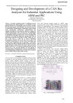
Автор: Vincent Claes Источник (англ.): FPGA PLATFORM WITH DATA-I/O CAPABILITIES FOR INDUSTRIAL AND EDUCATIONAL APPLICATIONS - 2. [Электронный ресурс]. – Режим доступа: http://pwo.fpga.be/LabVIEW/Lab%204%20Picoblaze.pdf Lab 2: Implementing Serial Communication in LabVIEW FPGA on the Xilinx SPARTAN-3E Board Keywords: LabVIEW, LabVIEW FPGA, Xilinx SPARTAN3E Starter Kit, Serial Communication, RS-232. Vincent Claes 2008 Vincent Claes Demo Version, http://www.verydoc.com and http://www.verypdf.com Introduction Welcome to Lab2 in the serie of programming a SPARTAN3E Starter Kit by use of LabVIEW FPGA. These labs are created by Vincent Claes. If you encounter problems using this labs or want some advice/consultancy on LabVIEW and especially LabVIEW FPGA you can always contact the author. These labs are free to use however to show respect to the author please email him when you use them with your contact details (feedback is also welcome). Contact Information: Vincent Claes [email protected] http://www.linkedin.com/in/vincentclaes Software Requirements: • LabVIEW 8.5 or above • LabVIEW 8.5 FPGA module • XUP Spartan3E starter board: download for free from: https://lumen.ni.com/nicif/us/infolvfpgaxilsprtn/content. xhtml Hardware Requirements: • Xilinx Spartan3E Starter kit: http://www.xilinx.com/products/devkits/HW-SPAR3E-SK-USG.htm • User manual: www.xilinx.com/support/documentation/boards_and_kits/ug23 0.pdf Getting Started When you want to use this labs you have to setup your board. This labs are written for the Xilinx SPARTAN3E Starter Kit so it is quite interesting to read the user manual of the board. Be sure to plug in the USB cable, plug in the Power cord and Switch the board on before starting the lab. Vincent Claes 2008 Vincent Claes Demo Version, http://www.verydoc.com and http://www.verypdf.com Step 1: Adding the FPGA I/O to your LabVIEW FPGA Project The first things we have skipped because it is the same as in Lab 1. Try to setup yourself an LabVIEW FPGA project for the Xilinx Spartan3E starter board. When you reach the step where you have to add FPGA I/O to the FPGA Project add the “DCE_TXD” and “BTN_SOUTH” I/O pins. Now add a FPGA vi for your Spartan-3E Starter Board and name it “FPGA_VI_Serial”. Your “Project Explorer” view will look like this: Vincent Claes 2008 Vincent Claes Demo Version, http://www.verydoc.com and http://www.verypdf.com Step 2: A quick overview of the Serial Communication Protocol. Interesting links: http://developer.apple.com/documentation/mac/Devices/Devices313.html http://digital.ni.com/public.nsf/websearch/2ad81b9060162e70862 5678c006dfc62 http://en.wikipedia.org/wiki/Universal_asynchronous_receiver/t ransmitter Serial Data Packet: The purpose of this lab is that we give an introduction to Serial Communication between the Xilinx Spartan3E FPGA and a Host PC. We will implement a Function where the FPGA is sending characters to the Host PC if the user is pushing a Button (“BTN_SOUTH”). We will send over a “Hello World!” message. The implementation of this “Hello World!” message is not in an optimized way; by this I mean I did not implement it in a Memory block which uses less space in the FPGA. In one of the next labs we will use the memory blocks. We will implement a LabVIEW FPGA VI that sends “Hello World!” over RS232 to our Host PC with the following settings: Bits per second: “115200”, Databits: “8”, Parity: “None”, Stopbits: “1” and Flow Control: “Hardware”. The first thing we have to do is convert our message to ASCII codes. We can do this by using the codetables on the following website: http://www.asciitable.com/ Try to do the conversion yourself. Here is my solution: 72 101 108 108 111 32 87 111 114 108 100 33 13 10. (The last 2 characters are there for showing a next received “Hello World!” message on the beginning of a newline (CR + LF character). Vincent Claes 2008 Vincent Claes Demo Version, http://www.verydoc.com and http://www.verypdf.com Step 3: Implementation The first step is to create an array that is filled with the elements of the message we wanted to send over to the Host PC. For this place a “Build Array” icon on your block diagram (FPGA_VI_Serial.vi). Extend it so it can hold 13 elements. Now connect U8 constants to the inputs of the build array function. Fill the constants with the message we want to send over. Because in this example we don’t want to change the message in runtime we place this code on the outside of our never-ending while loop. So for now create a “While Loop” where you connect the output of the build array with. Be sure to check out “Disable Indexing”. Connect a boolean “False” constant to the conditional terminal of the “While Loop”. We only want to send out the message when the user is pushing the “BTN_South” button, so we need to implement a case structure. Place a “Case Structure” in the “While Loop”. As input to this “Case Structure” we need to connect the value of the “BTN_South”. Do this by placing a “FPGA I/O Node” on the block diagram of the FPGA_VI_Serial.vi application. This Vincent Claes 2008 Vincent Claes Demo Version, http://www.verydoc.com and http://www.verypdf.com I/O Node must been placed inside the “While Loop” you just created”. Now place a “For Loop” with a constant of “14” connected to “N” in the “True case”. Now it is time for the actual RS-232 communication. For this we are creating a “Sequence Structure” where we explicitly send over each bit of the RS-232 packet. So for now create a “12 frames long” sequence structure inside the “For Loop” you just created. Vincent Claes 2008 Vincent Claes Demo Version, http://www.verydoc.com and http://www.verypdf.com Because we are using “115200 bits per second” each bit we will send is 1/115200 seconds long. This is 8,68 µs. We are rounding this value to 9 µs. Place in each frame of the sequence structure a Wait VI and set Counter Units to “uSec”. For the first frame wire a constant of “17” to the “Wait” vi. For the last frame of the “Sequence Structure” wire a constant of “50” to the “Wait” vi. For this last sequence also put the “Counter Units” to “mSec”. For all the other frames wire a constant of “9” to the “Wait” vi. Now we have get the ascii-codes back out of the array. And after this step we need to convert them into binary format to send them over. We are doing this by placing an “index off” function inside the “For Loop”. We connect “i” (the iteration of the For Loop) to the index input. Vincent Claes 2008 Vincent Claes Demo Version, http://www.verydoc.com and http://www.verypdf.com Now place a “Number to Binary Array” function next to the “index off” function to convert the numbers to binary format. Wire the output of the “Build Array” function to the input of the “index off” function. Now your block diagram should look like the following screenshot: You see there is a problem. The problem can be fixed by right clicking on the yellow square that is the input to the “For Loop”. Select in the pull-down menu the option “Disable Indexing”. Now we can separate all the ASCII-codes out of the array. But we need to convert those ASCII-codes to binary values for sending them over to the Host PC. Here for we use again the “Index of” function. Out of this function we get the ASCII code of the character we want to send in binary format. Vincent Claes 2008 Vincent Claes Demo Version, http://www.verydoc.com and http://www.verypdf.com The last part is sending all out as a serial communication data packet. For this we place in all the frames of the sequence structure an “I/O Node” with “DCE_TXD” as the “I/O item”. Now check the Serial Communication Packet again: I have implemented also “Idle” periods for this lab. To be sure that the Host can handle the information he receives. Connect to the first “DCE_TX I/O Node” a True constant. As the second “DCE_TX I/O Node” we have to send over a False (Start Bit; look at the image Space and Mark). For “DCE_TX I/O Nodes” that come after the start bit you have to send over the bits from the ASCII code you want to send over. So connect the Vincent Claes 2008 Vincent Claes Demo Version, http://www.verydoc.com and http://www.verypdf.com output from the “index of” function to the remaining “DCE_TX I/O Nodes” in a correct order. You now see there is one “DCE_TX I/O Node” not connected. This is the stop Bit. Connect a Boolean “True Constant” to the last “DCE_TX I/O Node”. Now I have some goods news: the FPGA vi is finished. So now save the “FPGA_VI_SERIAL.vi” and do a “right mouse click” on the “SPARTAN 3E Starter Board” target in your “Project Explorer”. Select “Properties”. Select the “Run when loaded to FPGA” option and press the “OK button”. Vincent Claes 2008 Vincent Claes Demo Version, http://www.verydoc.com and http://www.verypdf.com Now go back to your “Project Explorer” view and do a “right mouse click” on the “FPGA_VI_SERIAL.vi”. Select “Compile”. Now you have some time to search yourself a RS-232 cable and connect it to a HOST PC and the DCE port of the Spartan3E starter board. Step 4: Try it! After you get the message from the Compiler Server everything is compiled you can start “Hyperterminal” (a Windows Application). In hyperterminal we will show the message we are getting from the Xilinx Spartan3E Starter board. Be sure to make the following settings: Vincent Claes 2008 Vincent Claes Demo Version, http://www.verydoc.com and http://www.verypdf.com I am sorry that this screenshot is in “Dutch language” since I am not a native English speaker. Now do a “Right mouse click” on the “FPGA_VI_Serial.vi” and Select from the pull-down menu “Download VI to Flash Memory”. Press the “OK” button. If you now press the “BTN_SOUTH” on the Xilinx Spartan3E Starter board and you have connected the serial cable in a correct manner you will see a “Hello World!” message appear in your HyperTerminal screen. Vincent Claes 2008 Vincent Claes Demo Version, http://www.verydoc.com and http://www.verypdf.com Enjoy. Vincent Claes XIOS Hogeschool Limburg Department of Industrial Sciences and Technology Universitaire Campus - Agoralaan – Gebouw H B-3590 Diepenbeek Belgium [email protected] tel.: +32 11 26 00 39 fax: +32 11 26 00 54 mobile: +32 478 35 38 49 Vincent Claes 2008 Vincent Claes Demo Version, http://www.verydoc.com and http://www.verypdf.com