1
Bachelor Degree Project
HIGH-LEVEL LANGUAGE DESIGN
for IMMA-Virtual Driver DHM Research
Bachelor degree project in Product Design
Engineering G2E
22.5 ECTS
Spring 2015
Beñat Garay García
Supervisor: Lars Hanson
Co-supervisor: Dan Högberg
Examiner: Peter Thorvald
Assurance of own work
This project report has on 6th of June of 2015 been submitted by Beñat Garay to
University of Skövde as a part in obtaining credits on basic level G2E within
Product Design Engineering.
I hereby confirm that for all the material included in this report which is not my
own I have reported a source and that I have not – for obtaining credits –
included any material that I have earlier obtained credits within my academic
studies.
Beñat Garay García
I
High-level language design for IMMA-Virtual Driver DHM Research
Abstract
The growing implementation of ergonomics in the automotive sector sets high
demands on Digital Human Modelling (DHM) functionalities towards the
simulation of more realistic environments and the reduction of physical model
dependency. During the current degree project a leading element that smartly
assembles DHM usage (implementation of high-level commanding languages)
was designed, revolving around the industries’ needs which were gathered and
interpreted in order to organize current functions in this language and suggest
new complementary functions that would create a language environment
suitable for non-expert users. This was achieved by focusing in an intuitive
word-function structure, the proposal of defaults and other tools that aid users
with different kinds of expertise. The need for realism of simulations was
assessed by the language design especially by designing means to coordinate
synchronic manikin-actions.
II
High-level language design for IMMA-Virtual Driver DHM Research
Table of Contents
1
INTRODUCTION....................................................................................................... 1
1.1
BACKGROUND & CONTEXT ....................................................................................... 1
1.1.1
HIGH-LEVEL LANGUAGE AND IMMA........................................................................ 2
1.1.2
OTHER DHM IN THE AREA OF IMMA ...................................................................... 3
1.1.3
A SPECIALIZED AREA ............................................................................................. 3
1.2
PURPOSE & OBJECTIVES ......................................................................................... 4
1.3
LIMITATIONS ............................................................................................................ 5
1.4
OVERALL DESIGN STRATEGY .................................................................................... 5
1.4.1
DIFFERENTIATING ASPECTS OF THE PROJECT ......................................................... 5
1.4.2
DEFINING A DESIGN STRATEGY .............................................................................. 6
1.5
METHODS IN EXPLORATION PHASE ........................................................................... 7
1.5.1
CONTACT ............................................................................................................. 7
1.5.2
ANALYSIS ............................................................................................................. 8
2
THEORY BACKGROUND ...................................................................................... 11
2.1
DIGITAL HUMAN MODELLING (DHM) ...................................................................... 11
2.2
OCCUPANT PACKAGING ......................................................................................... 11
2.3
DHM IN VEHICLE ERGONOMICS .............................................................................. 13
2.3.1
IMMA’S CURRENT CAPABILITIES THAT INFLUENCE THE HIGH-LEVEL LANGUAGE ...... 13
2.3.2
OBSERVATIONS AND FEATURES FROM JACK 8..................................................... 17
2.4
III
HIGH-LEVEL LANGUAGE DESIGN IN DHM ................................................................ 19
High-level language design for IMMA-Virtual Driver DHM Research
2.5
ABOUT A USER-CENTRED SYSTEM DESIGN .............................................................. 20
2.6
STUDY VISITS TO COLLABORATING VEHICLE COMPANIES ......................................... 21
2.6.1
STUDY VISIT TO VOLVO TRUCKS .......................................................................... 21
2.6.2
STUDY VISIT TO SCANIA ...................................................................................... 22
2.6.3
STUDY VISIT TO VOLVO CONSTRUCTION VEHICLES ............................................... 23
2.6.4
QUESTIONNAIRE TO VOLVO CARS ........................................................................ 24
3
PRODUCT SPECIFICATIONS ............................................................................... 25
3.1
GENERALITIES ....................................................................................................... 25
3.2
REQUIREMENTS & WISHES ..................................................................................... 25
3.2.1
CONTENT ........................................................................................................... 26
3.2.2
QUALITY ............................................................................................................. 27
4
GENERATION & DEVELOPMENT ........................................................................ 28
4.1
METHODOLOGY FOR GENERATION AND DEVELOPMENT ........................................... 28
4.1.1
FIRST LANGUAGE CONCEPT ................................................................................. 28
4.1.2
FOCUS GROUP .................................................................................................... 28
4.1.3
EXPERT VALIDATION............................................................................................ 29
4.2
FIRST CONCEPT APPROACH ................................................................................... 30
4.3
FOCUS GROUP ....................................................................................................... 32
4.4
VALIDATION FROM SOFTWARE DEVELOPERS AND FURTHER ADVICE ......................... 34
4.5
FINAL CONCEPT ..................................................................................................... 35
5
EVALUATION ......................................................................................................... 36
5.1
METHODOLOGY FOR EVALUATION .......................................................................... 36
5.2
SELF-EVALUATION: IMMA MANUALLY VS. IMMA WITH THE NEW LANGUAGE ........... 37
IV
High-level language design for IMMA-Virtual Driver DHM Research
5.3
6
FEATURE COMPARISON: IMMA - NEW LANGUAGE VS. JACK 8 ................................. 40
DISCUSSION .......................................................................................................... 42
6.1
DEFINITION OF THE WP3 ........................................................................................ 42
6.2
LITERATURE STUDY ............................................................................................... 42
6.3
SOFTWARE ANALYSIS ............................................................................................ 43
6.4
STUDY VISITS WITH COLLABORATORS .................................................................... 44
6.5
DESIGN STRATEGY AND METHODS .......................................................................... 44
6.6
RESULTS ............................................................................................................... 45
6.6.1
PRODUCT SPECIFICATIONS (AIMS FOR THE PRODUCT) .......................................... 45
6.6.2
GENERAL AIMS AND CONTRIBUTION FOR IMMA .................................................... 46
6.7
7
GENERAL DISCUSSION AND FOLLOW-UP IDEAS ....................................................... 47
CONCLUSIONS...................................................................................................... 49
REFERENCES ............................................................................................................. 50
APPENDIX 1: QUESTIONNAIRES ................................................................................ 2
APPENDIX 2: FOCUS GROUP ..................................................................................... 4
APPENDIX 3: TASK ANALYSIS EVALUATION ........................................................... 7
APPENDIX 4: FEATURE COMPARISON (IMMA/JACK) ............................................ 24
APPENDIX 5: FINAL CONCEPT DEMONSTRATOR ................................................. 26
V
High-level language design for IMMA-Virtual Driver DHM Research
Glossary & Abbreviations
WP3
Work Package 3
The current project
It refers to the initial description of the current project as defined
by the Virtual Driver Project, which encompasses several
parallel projects of which some of them are “Work Packages”
like the present. This WP3 contraction is mainly used
throughout the report when the initial definition of the project is
wanted to be remarked.
WP2
Work Package 2
Pamela Ruiz de Castro’s project
IMMA
Intelligently Moving Manikin
WP2 stands for Pamela Ruiz de Castro’s project also carried
within Virtual Driver, “Seating Comfort analysis for Virtual Driver
Research”, as named by the Virtual Driver Project
encompassing different projects. The acronym is used to shortly
refer to a work that although it may be relevant for the current
one, as it is parallel to it, it will be unfinished in the course of the
present project, making it difficult to reference it otherwise.
DHM software involved in the
current project
The IMMA Digital Human Modelling software was born in 2009
thanks to the join of University of Skövde, Fraunhofer-Chalmers
Research Centre, Chalmers University of Technology, Volvo
AB, Volvo Cars and Scania. It is able to predict both postures
and motions by the use of mathematical algorithms instead of
the usual motion and posture captures.
VI
High-level language design for IMMA-Virtual Driver DHM Research
1 Introduction
1 Introduction
The present chapter aims to introduce the foundations on which the current
bachelor’s thesis was carried out. Thus, background and context matters, the
purpose of the project and some limitations will be discussed.
1.1 Background & context
Bhise (2012) states that while the implementation of ergonomics in vehicle
design has improved user comfort, convenience and safety substantially in the
last three decades, the current rapid technological development makes the
future needs for assessments in this field even greater.
Ergonomic assessment in vehicle industries is usually aided by Digital Human
Modelling (DHM) especially at early stages in the design process. However,
existing competent alternatives require expert usage-skills; in addition, the
features they offer are often insufficient considering ongoing and future
demands in the sector. The renowned German ergonomist Heiner Bubb
suggests some prospective features the sector is increasingly valuing for DHM:
"At some point we will be able to check the entire ergonomics in the vehicle
digitally. New software, new studies and new applications will pave the way for
us to achieve this. [...] The primary new issues are automated motion and
cognition. And for me, the vision behind this is RAMSIS someday tackling
completely situation-dependent tasks. For example: ‘Drive on the freeway and
turn on the radio’.” (Human Solutions, 2013, p.3, p.11)
The hereby reported design research project was concluded within the field of
vehicle user ergonomics oriented DHM, this being part of a larger research,
Virtual Driver, which encompasses several collaborating entities: FraunhoferChalmers Centre, Högskolan i Skövde, Scania, Volvo Cars and Volvo AB.
Virtual Driver’s general purpose is IMMA (Intelligently Moving Manikin) DHM
software by Fraunhofer-Chalmers Centre (2009-2014) to reach a version that
can ambitiously assess user ergonomics for car, truck, bus and construction
vehicle users from early design stages. It is to consider that IMMA was originally
built within the previously mentioned collaborator’s alliance aiming ergonomic
verification of workers in vehicle assembly lines, as Hanson et al. (2014)
explain.
It should be pointed out that IMMA, together with a parallel project called
CROMM (tackling muscular biomechanical simulations), is distinguished for the
use of sound mathematical solutions, which open a broad range of new
1
High-level language design for IMMA-Virtual Driver DHM Research
1 Introduction
horizons like kinematic analyses in the near future. On the contrary, other
known virtual tools in the area are founded on postural and motional recorded
data as a very central element for the software’s working core.
1.1.1 High-level language and IMMA
Since this project targets the creation of a new high-level language design for
IMMA, it should be first made clear what is meant with high-level language.
High-level, in the present context refers to the level of abstraction. In fact, these
languages would be in a similar level of abstraction of the terms we could use to
generally and briefly describe what a manikin is doing when a simulation being
run. Notice that as Coughlan (2014) mentions, well-known programming
languages like C, C#, Java, Pascal, Basic or COBOL, are high-level languages.
Nonetheless, it is not a programming language what it is being designed here,
but a language that acts itself as a user interface environment resource
between the features of the software (IMMA) and the user, therefore being
much higher in abstraction than any of the mentioned program languages.
Thus, this language is the hierarchically structured compound of words that
encompass different actions and options that will call to software’s current
resources, functions and capabilities in order to set the different elements of the
scene (consult chapter 2.4), including objects, paths, manikins and acting
geometries so that simulations of manikin-tasks can be performed. Therefore,
considerable knowledge on these elements and features of the software in
which the language design is to be implemented (i.e., IMMA) is crucial to
succeed in the design of it. These relevant characteristics are addressed in
chapter 2.3.1.
Alike some other DHM software and as Mådberg et al. (2014) explain, IMMA
currently has a high-level language tool which allows ordering abstract
commands to the manikin rather than having to plan every single joint’s
translation and rotation individually throughout different time frames; the tool is
presently called ‘Language Operation Editor’. However, this project would not
have any reason for being without recalling the previously stated fact that the
current IMMA version and its language, consequently, are not designed to
assess vehicle-user tasks but vehicle-assembly worker’s tasks. For this reason,
adapting the capabilities and features of the software in the language design for
vehicle-user oriented workflow will be the catalyst to achieve the aims this
project is proposing.
2
High-level language design for IMMA-Virtual Driver DHM Research
1 Introduction
1.1.2 Other DHM in the area of IMMA
There are several software alternatives in the DHM field when it comes to
assess user-vehicle ergonomics. However, due to industries preferences and
characteristics of some of the software, the ones that are going to be dealt with
in the current project (in addition to IMMA, of course) are mainly Ramsis and
Jack, and secondarily Delmia Human.
Jack can be considered as a suitable benchmark when it comes to the
language due to its leading Task Simulation Builder (manikin commanding highlevel language), which is, as IMMA’s current one, fully oriented to worker task
assessment. Jack’s Occupant Packaging Toolkit (including numerous SAE
standards and car-centred ergonomic applications) was also tested. However,
even though it could be considered as quite complete, as mentioned in WP2
(check glossary), the default seated postures are centred on seated work tasks.
Thus, particularly when referring to vehicle ergonomics, this software seems not
to be as widely accepted in the sector as other.
On the contrary, Ramsis seems to be the preferred software in most
collaborating entities. The software is completely vehicle oriented, and because
it is much more settled down in the vehicle industry, some of its features are
very specifically oriented to assist vehicle ergonomics. Nevertheless, it was
noticed that Ramsis does not have any manikin-task commanding language
(the “Task Editor” name of one of its functionalities can be misleading in this
regard). Therefore, and considering that collaborators were going to show their
usage of it, its previous analysis was not as prioritized as Jack’s. In the end,
knowing better different software avoids biasing of particularly one of each
when implementing new ideas.
Delmia Human is also settled in one of the collaborating entities. However, it
was confirmed in the first workshop with them that it lacks many features and
several modifications had to be done to the software just to fulfil a bare pass in
their demands. For this reason, it was not further analysed.
1.1.3 A specialized area
It is also important to be aware that the field in which the project is held involves
specialized concepts, terminology, standards and an essential need of
understanding the software on which this project revolves around. Thus,
chapter 2 that follows will cover some essential aspects that will address to
build a frame of reference to understand the consequent design decisions and
in parallel, prevent the reader from possible confusions.
3
High-level language design for IMMA-Virtual Driver DHM Research
1 Introduction
1.2 Purpose & objectives
The general aim of the Virtual Driver project is to meet industries’ needs
regarding DHM in a new version of IMMA oriented to vehicle-user ergonomics.
In this approach, reliability and repeatability of results, usability and avoidance
of user’s subjective criteria that affect outcome are essential.
As for the present project, the scope focuses in the design of a high-level
instruction language for the ongoing development of IMMA-Virtual Driver to
simulate manikin-tasks that vehicle industries (cars, busses, trucks and
construction vehicles) demand, and inspire other solutions for the future.
Moreover, the capabilities or features of IMMA through the new language
should be compared with other software. Jack was the software considered
most adequate for the comparison, due to its TSB and OPT functionalities
explained before (and more in detail in chapter 2.3.2).
The high-level language should preferably:
Be easy and intuitive to use for new non-recurrent users mainly when it
comes to setting manikin actions.
Gather and interpret the industries’ specific needs in relation to what the
high-level language can provide or facilitate. Apply the identified needs in
the language as far as limitations of the project allow.
Guarantee the possibility to set the manikin to perform all the occupant
packaging tasks that vehicle industries usually ergonomically evaluate
through this kind of tool and as far as possible new tasks that they would
find advantageous to evaluate; these prioritized as follows:
o Primary driving tasks (required)
o Secondary occupant packaging tasks (demanded)
o Visibility related manikin-setting (highly wished)
o Ingress/egress and vehicle service (if there is time)
Ensure good balance in its design, meaning that the set of available
instructions conforming the core of the language (e.g., ‘steer wheel’) that will
allow users create complete operations will optimize mainly these two rival
aspects: a reasonable amount of available instructions (i.e., not too crowded
of different commands in a same level) vs. sufficiently specific and wellorganized instructions that will cover the presumed big range of required
particular actions allowing sufficiently straight-forward/intuitive commands.
Help both configurability and repeatability. This can involve areas that
surround the language like: the design of criteria and examples for defaults
and configurability options, external management tools for simultaneous
instructions and/or the implementation of easy and fast input in the language
display environment. Although this it is not strictly central to the project it
4
High-level language design for IMMA-Virtual Driver DHM Research
1 Introduction
should help building a highly automatable and repeatable workflow as well
as fulfilling industries’ configurability demands according to their own
particular needs. It will also open a way for future improvements and further
inspiration.
Be self-evaluated by a demonstrator, comparing its performance with the
traditional (i.e., manual) operation of the manikins by employing software
demonstrators that implement the designed language versions.
Demonstrators are to be built by the original programmers along the current
project, and if not possible, explanatory demonstrators approved by them
should be showed.
*Some of the analysis/outcome that is not expected is explained in chapter
1.4.1
1.3 Limitations
Most limitations have been found during the course of the project and been
dealt with in order to come with solutions:
The high dependency for the language of input modes, current
capabilities, user interface, toolkits, etc.
Lack of time compatibility for the implementation of the concepts
concerning the development stage and pace of IMMA-Virtual driver and
the shorter time span of the current project.
Unreliable, inaccurate or unavailable literature information for specific
needs of the industries regarding the present objectives, creating some
dependency on the external collaborator’s input.
1.4 Overall design strategy
This section will cover design strategy that was followed and determines some
guidelines for methods that could be used, having as starting point the initial
conditioning and characteristic features of the project.
1.4.1 Differentiating aspects of the project
Even though not explicitly, it has been made clear so far in this report that this
project cannot be categorized as a regular product design project. Some of the
5
High-level language design for IMMA-Virtual Driver DHM Research
1 Introduction
intrinsic aspects that WP3 (see Glossary) presented in relation to the design
methodology and related implications are described as follows:
There is not a physical product to be designed: the current project should
remain in the area of a software environment. While physical means of
input, e.g., Kinect (https://www.youtube.com/watch?v=4FoeydgNjRU) or
Oculus Rift are starting to be implemented in the field, the development
of methods for the implementation of these or similar or technologies is
not in the scope of the current work. This implies that any design
methods exclusive for physical product design are not contemplated.
The design for appeal towards a specific market segment’s taste is not a
priority: if any user interface representations are created in order to
demonstrate concepts or propose complementary tools, there is not a
particular user-sector whom to create “special” experiences to, when it
comes to pure aesthetics (rather than functional). Therefore, although it
is an area that should be take care of in other project or work package
thoroughly, as for the current, desire generating related methods for
graphic interfaces will not considered.
The definition of the work is rather narrow: there are some design
projects where in the beginning even the type of outcome product is
unknown, or where even the problem can be solved without requiring a
product but a service or other solution instead. This is absolutely not the
case, and such extreme flexibility is not expected here since this is just a
part of a larger research project, Virtual Driver. Therefore, the creative
potential of the project lies in the interpretation and implementation of the
industries demands, so that a way to fulfil future needs can be built.
1.4.2 Defining a design strategy
The main pillar in which this project is settled is the discovery, interpretation and
implementation of vehicles industries needs that affect DHM ergonomic
evaluations, more concretely in what an instruction language could potentially
handle. Thus, interviews, meetings, workshops and/or focus groups with
collaborating entities are central and unmissable. In addition, the timing and
context of the project does not allow very roundabout seeking of alternative
solutions as previously suggested.
Cross (2008) mentions that usually, modern design work is responsible of
dealing with high-risk implications associated to mass production, costs and
safety, therefore not allowing the designer to make mistakes, needing thus an
extremely detailed design plan. In the current work, though, this principle does
not apply, since software can be updated any moment and what is more, the
6
High-level language design for IMMA-Virtual Driver DHM Research
1 Introduction
outcome will not be the final product of the larger project, but a considerable
source in which innovations will be inspired or based on, instead.
This is compounded by the a presumable unfamiliarity in the field of a very
specialized area, which awards a reason of being to the very first sub-stage
“Contact” described next. All this involves that the methods cannot be foreseen
in detail generally speaking. Adding to this the nature of the project described
so far, it can be presumed that methods will not be very varied and that some of
the procedures will be based on trial and error, both with the collaborating
companies and with the software developers.
Bearing all this in mind, the chosen strategy is a general one, containing
exploration, generation and evaluation phases. The communication of the
results is not so much a “showcase” to sell the product in this case, but the
product (language) being demonstrated and explained (with graphic aids). In
the following lines methods for the initial phase are described, whereas the
ones regarding generation, development and evaluation are explained in the
corresponding chapters, i.e., chapter 4 and chapter 5.
1.5 Methods in exploration phase
In this section, methods employed in phases prior the concept development are
described, this is, methods regarding exploration, stage that encompasses a
contact phase due to the context of the project and an analysis phase, as usual.
1.5.1 Contact
Keeping in mind the unfamiliarity with the area mentioned before, this phase is
aimed to acquire enough familiarity within DHM in automotive ergonomics, highlevel language design in this area and related aspects in order to be able to
carry out further research.
Approach to IMMA and initial testing
On the one hand, IMMA software and especially its language should be
well understood, having considerable command on it. In this regard,
IMMA was tested and tried to perform some of the actions that the
language was not designed for originally. This way, the software could be
learned and at the same time tested to seek for lacking needs and
features that are important to take into account when it comes to
resources that the language needs to call and coordinate.
In the beginning the manikin was tried to be set in a seating position and
trough different constraints try to work out in a rudimentary way how
7
High-level language design for IMMA-Virtual Driver DHM Research
1 Introduction
these constraints should work so that they can be automatized in the
language. Later on, different tasks like steering the wheel or moving the
shifter around were manually performed or using the current worker
oriented language when possible, in order to see what are the limits of
the current available language when it comes to sitting occupant
packaging tasks.
Many results from these testing that were found too varied, full of
subtleties, and very difficult to gather in some tangible results were an
important part of the background knowledge for the designer that can be
noticed later in the questions and issues tackled in the different
workshops more practically.
Tangible results were of course gathered. However, it is about more
overall understanding of the general features of IMMA that are relevant
for the language design. This could be noticed in chapter 2.3.1.
Initial literature research
A first approach to the literature research was also done with similar
purpose of familiarization and determination, in the topics of Vehicle
ergonomics and related DHM. Although some standards, concepts and
terminology might not be used, it is important to get to know them in
order to understand the logic behind them, how things have been done
so far, and so forth. Many of this information form just a mental
framework which is necessary, but that does not intend to come with any
direct output for the research, and will not be reported in the results’
phase, since any outcome of it will be reflected in the following substage’s results.
This stage was also intended to include visits to collaborating companies,
in order to perform second thorough focus groups with all collaborating
entities, but eventually it was not possible to know their working
environment and primary needs in the time this contact phase was
supposed to take place, and eventually only one focus group could be
performed after the three study visits held through the Analysis phase.
1.5.2 Analysis
This exploration sub-stage is mainly aimed to get better understanding of the
field with literature research, and analysing more in detail the features of IMMA
and other software that can be inspiring or useful for the new design, in order
also to improve preparation and realization of workshops with suitable experts
at the collaborating companies later on. Initial study visit meetings (mentioned in
the previous point “Contact”) were delayed; therefore, this stage encompassed
those study visits (enabling to set the specifications with which the stage should
8
High-level language design for IMMA-Virtual Driver DHM Research
1 Introduction
close), and initially planned workshops were moved to the “Generation” phase
as an evaluation tool to improve concepts and propose upgrades for the future.
IMMA testing
Testing in the current stage was done more thoroughly to complete
previous stage’s with similar procedure, but in this case, as more detailed
trials were carried out a constant conversation with IMMA software
developers was kept, since the more complex the tasks were tried out,
the more difficult it was to make out whether it was a bug of the software
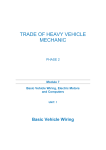
or results that are not expected from the software (see Figure 2.2).
Figure 2.2
Test trials in current IMMA version simulating driving tasks.
Jack testing
Competitors’ software is also to be learned to some extent to have a
general idea of what are the features that can be most interesting and
have some benchmark. This was made for Jack 8 (TSB and OPT, see
chapter 2.3.2) mainly, since its Task Simulation Builder (especially) and
Occupant Packaging Toolkit were considered leading benchmarks for the
current purpose.
Jack (general) user-guide was generally scanned and parts related with
the language and aims of the current design (e.g., animation, easy
snapping, visibility…) were read more in detail.
The user-guide for the Task Simulation Builder was entirely read and all
included tutorials were performed so that the main capabilities of it were
understood and embraced.
9
High-level language design for IMMA-Virtual Driver DHM Research
1 Introduction
The same thorough read and tutorial performing was carried out with
Occupant Packaging Toolkit.
Once finished, results were gathered. Only interesting features in relation
to the language design are mentioned in chapter 2.3.2.
Study visits
In the current study visits, each collaborator was responsible to organize
a workshop were they would show their workflow in general and
particularly with the DHM software they use. All the visits were
coordinated for both WP2 and WP3 therefore answering matters from
both projects that were sent in advance. These questions are included in
the appendixes.
Workshops were audio recorded so that details would not be missed and
the focus during the interview could be in asking on-the-go questions.
10
High-level language design for IMMA-Virtual Driver DHM Research
2 Theory background
2 Theory background
The present chapter aims to explain common concepts in the field of Digital
Human Modelling and recurrent standards and terminology of automotive
ergonomics as well as some high-level language design oriented principles. In
addition, capabilities from the studied software including current IMMA and Jack
8 (with TSB and OPT) will be included in this section. Thus, a good
understanding on the some of the basic principles around which the results are
founded in is to be obtained.
2.1 Digital Human Modelling
Digital Human Modelling (DHM) is known as a digital representation of the
human body in a simulated virtual environment which aims to allow analysing,
calculating and therefore, foreseeing a wide array of matters where the body
performance or safety is involved, from ergonomics of products and workplaces
to applications in the field of medicine. This enables engineers reducing or even
getting rid of the dependency of physical prototypes which can be very
expensive and less flexible, especially in early design stages (Duffy, 2008).
2.2 Occupant packaging
In the automotive industry, the expression “occupant packaging” refers to the
activities and location of components and systems in the vehicle space,
including occupants that must be accommodated together with all these
elements in the vehicle. Design considerations for the development of the
occupant packaging can be grouped in entry/egress, seat comfort, hand and
foot controls, visibility of interior and exterior, storage spaces and vehicle
service and maintenance (Bhise, 2012).
When it comes to the interaction of the driver (and possible passengers) in the
vehicle, there are some standardized dimensions. Next, the ones considered
basic and relevant for the understanding of the development of the new IMMAVirtual Driver’s language are described as in Bhise (2012). After each
description comments are also made regarding considerations of each of them
regarding the current project:
11
High-level language design for IMMA-Virtual Driver DHM Research
2 Theory background
Accelerator Heel Point (AHP): it is the point in the shoe that touches
the vehicle floor when the foot is heel supported and laying on the
accelerator pedal, being the foot coplanar with the pedal plane (see
Figure 2.1).
This point is most often used as the principal reference for all the
measurements, both in SAE standards and in most of the collaborating
entities workflow.
The idea of AHP, in addition to other non-standard heel points has been
also implemented (see chapters 2.3.1 and 4) as a resource for assessing
different pedals.
H-Point and SgRP: the H-point (hip point) is the imaginary point in which
the upper body and the legs would articulate around, where “back line”
and “thigh line” would intersect. The SgRP (seating reference point) is a
widely used point which is a specific location of the H-point near when
the seat is near its rearmost position in the seating track, usually at the
95th percentile of the horizontal distance (X95) of the H-point (measured
from AHP), as recommended by SAE.
The H-point has been confirmed as an essential point to locate the
passengers (or manikins in DHM) in the seat (see chapters 2.3.1 and 4).
Ball Of Foot (BOF): this is the assumed as central pressure point of the
foot in the accelerator pedal plane, which corresponds to the top portion
of the driver’s foot.
This point (more accurately the concept, rather than a static
measurement from AHP) has been useful for the implementation in the
language workflow (see chapters 2.3.1 and 4); it was considered as a
moving (sliding) point in the case of pedals where there is heel support,
having thus a dependence on the pedal plane angle (see A47 in Figure
2.1) when there is motion in the pedal controls.
12
High-level language design for IMMA-Virtual Driver DHM Research
2 Theory background
Figure 2.1
Interior package reference points and dimensions (Bhise, 2012).
2.3 DHM in vehicle ergonomics
As Gkikas (2013) mentions, the sector where DHM has been most applied is
the automotive industry, with SAE (Society of Automotive Engineers) having
had a big influence through standards, committees and conferences.
As previously discussed, the software that is to be feature-wise analysed most
thoroughly in this work are IMMA and Jack.
2.3.1 IMMA’s current capabilities that influence the high-level
language
In order to be able to build a suitable and successful language for IMMA, it is
crucial to understand well enough IMMA’s current features that will have some
impact in that language design that could be identified after several testing.
When considered opportune, comparisons with other software may be pointed.
13
High-level language design for IMMA-Virtual Driver DHM Research
2 Theory background
1. TCPs, Joint control, constraints and inverse kinematics
In IMMA joints are controlled by TCPs or Tool Centre Points, being these
positioned in each articulation. TCPs are both translation and rotation
constraint-wise configurable and for each joint TCP there are also
predefined constraints to adjust each articulation’s angles with sliders, one
axis at a time using higher usability comprising terminology (in/out, twist…).
Joints can also be translated and rotated just by dragging and/or orienting
their TCPs manually in the scene window so that the whole body will adapt
to a posture that fulfils both all the TCP constraints (using inverse
kinematics) and balance and ergonomic posture optimization algorithms
(explained later). So for instance, if we wanted to locate the hand in a
certain placement and orientation and want this inverse kinematics acting
only in the arms joints, we would need to fully lock the rest of the body and
then move the wrist’s TCP around.
2. Initial posture, balance and posture prediction
Most current initial postures in IMMA have a couple or three TCPs active
and constrained by default. In other software like Ramsis, initial postures
have more impact in the predictions afterwards made than in IMMA,
meaning that when a posture is chosen in Ramsis, all constrained motion
created after will have the effect of some certain criteria related to that
specific initial posture (truck seating, for instance) when it comes to predict
new postures derived from user defined constraints.
IMMA works differently instead: the posture prediction criteria do not belong
to initial predefined postures. Thus, once an initial posture is chosen, all the
TCP constraints explained in point one are going to work together with
always the same posture prediction criteria regardless of the initial posture,
that encompasses two main foundations:
a) The balance criteria: not only makes sure the manikin is in equilibrium
throughout all frames of the motion, but it also provides the most solid
position if new external forces came into the scene.
b) The comfort criteria: among the usual infinite possibilities to fulfil the
all the constraints as a result of commands or manually generated
motions, this criteria will attempt to come up with a postural solution
for each single motion frame that is most ergonomic or comfortable.
This includes criteria like joint angle strategies (covered in WP2).
Thus, posture prediction calculates postures for a series of static frames to
get a statically solvable and comfortable posture all along the motion that is
created. This must not be mixed up with kinematics (which are intended to
be implemented in the future), since in the present version there is no
dynamic inertia considered in the equations beyond calculations. However,
14
High-level language design for IMMA-Virtual Driver DHM Research
2 Theory background
the current system allows estimating and evaluating time spent in potentially
unwanted postures along the way from posture A to posture B.
3. Grip points, support points and seating points
The grasping function has seen to have four main concrete functions:
a) Create wrist’s TCP position and orientation entities in respect to an
object to be accessible for any calculation at any time.
b) Allow external forces for calculations (feet TCPs also allow these).
c) Help to locate wrists TCP properly in respect to the object by
configuring the grasp shape of the fingers, even if fingers don’t take
part in force calculations.
d) Obtain good quality animation and visual output regarding grasping.
When it comes to support points, they aim to match TPCs similarly to
grasping points, but to objects that are supposed to act as static supports
rather than be moved by the manikin, so they also require for a force
supporting TCP, i.e., hands or feet.
Seat points seem to add modifications to the general criteria after which the
manikin is behaved. However, as manikin-actions for the current project will
be designed for seating postures mainly, this distinction is omitted.
4. Object paths, anchor frames and reference points
IPS (Industrial Path Simulations) will be merged with IMMA in the future. For
this reason, in the current software, the path generation and anchor frame
system (reference systems) is not expected to be improved. So in the
present, simple paths are generated for objects: from point A with orientation
A to point B with orientation B.
In this path generation, anchor frames, which could be seen as the single
reference system of an object, would determine the rotation reference. For
this reason, in a hinge mechanism (the most common in vehicles interaction
elements) it makes it much easier to place the anchor frame aligned with the
hinge edge. Likewise, in a ball and socket joint (like in the gearshift) the
anchor frame would be place preferably in the centre of the rotating ball.
Thus, object articulation is not fully user friendly in the present version.
Reference points can be used to move objects to, manually or via language
instructions. These are points created for an object in a relative position in
respect to another object. Therefore, at least two objects must be loaded in
the scene to be able to create reference points.
15
High-level language design for IMMA-Virtual Driver DHM Research
2 Theory background
5. Motion, timing and collision avoidance
As explained before, a sort of static based motion is generated. IMMA
divides actions in frames and sets of frames (segments). The time that each
segment takes is calculated by the software and it is also user modifiable.
In addition to TCP constraints balance equations and comfort criteria, there
is a checkable box called “collision avoidance”. This criteria makes sure that
the manikin will move without colliding itself or the objects around.
However, and unlike with the manikin avoiding collision with itself, when it
comes to manikin-object collisions, the manikin will stop any part of the body
that is to collide with any object when the most direct balanced and
comfortable way to fulfil constraints requires so. Therefore, a less solid
posture (but still balanced and as comfortable as the collision avoidance
allows) will be acquired. Nevertheless, this does not mean that the manikin
will, for example, surround objects that are in the shortest way of the arm
when it has to grasp an object, but it would stop before colliding with them.
In other words, the manikin will stop the parts of the body that collide
throughout the motion and try to reach whatever it was ordered to reach with
the remaining parts, but does not still have the ability to automatically create
longer paths for limbs that will go around objects, it must be guided breaking
down the action into smaller steps, if this happened.
6. Visibility and staring at objects
Visibility features in IMMA are currently quite limited in respect to other
specialized software and some DHM tools. There is the option to have the
manikin’s viewpoint (vision window), show eye cone (ambinocular vision
only), and staring at a point.
7. Manikin families
Manikin families allow having the same constraints for a batch of manikins.
So an operation or a manual TCP drag can be carried out simultaneously for
all these manikins. If any of those couldn’t fulfil the constraints (reach a
grasp, not collide, etc.), they would independently stop without affecting the
other manikins in the family. This is very useful to optimize operation setting
and avoid repetition, as well as obtaining repeatable results, avoid user
errors and identify meaningful cases.
8. Current language’s structure
The current language in IMMA works with operations and instructions. There
is a ‘Language Operation Editor’ and inside this, in a separated window, the
16
High-level language design for IMMA-Virtual Driver DHM Research
2 Theory background
‘Language Instruction Viewer’. In the first, instructions can be managed to
create operations (mainly created and put in order). In the second,
instructions itself are created through available manikin-tasks comprising
different available user-generated data. In principle, this structure is not
aimed to be changed, although the possibilities each of these offer, are of
course to be redesigned and enhanced by the design approaches.
2.3.2 Observations and features from JACK 8
As previously mentioned Jack DHM software was tested (aided by included
user guide and tutorials) especially due to its high usability interface and TSB
and OPT functions. Considerations of interesting features are described below.
General
There are several different entities that can be snapped when moving an object.
This is very interesting for IMMA-Virtual Driver as long as it could be
implemented in order to be integrated in the instruction language to speed up
the workflow. Among these, sites (as called in Jack, they can be understood as
reference systems or tool center points as currently in IMMA), nodes, edges
and faces, are the most interesting.
When the user wants to accurately match a specific point of an object (e.g., Hpoint in a manikin) place- and orientation-wise with an entity of another object
(e.g., H-point in the car model) the site snapping seems the most suitable.
On the other hand, when hands or feet are wanted to be positioned specifically
laying on the pedals or grasping the wheel respectively, snapping geometries
faces together is a fast way of positioning these limbs in a quite accurate way.
Occupant Packaging Toolkit
This Jack’s add-on tool has a quite complete set of functions that facilitate
placing the H-point in a vehicle design according to different SAE standard
measurements that can be quite easily measured with measuring functions
available in the regular scene window workspace.
Once all this data is entered, SgRP point, eyellipses (ellipsoids for the
representation of the eye location distribution) and different reach surfaces
(surfaces usually used to visualize the reachability of a manikin under certain
posture and constraints) can be displayed.
There is also a posture prediction tool founded on UMTRI’s research published
in SAE. Being the input the measurements of the car taken previously and
17
High-level language design for IMMA-Virtual Driver DHM Research
2 Theory background
choosing a car model of the list for the posture’s criteria of the mentioned
research, a posture is generated; the manikin will be placed holding the wheel
with both hands (10/2 clock grips) and laying the right foot on the accelerator.
Task Simulation Builder
The task simulation builder, which would be the equivalent of IMMA’s instruction
language, has some potentially relevant functions to be considered when
designing the new language. Similarities with the general aims of this project
can be found in the next extract from the Jack User Manual version 8.2 (p.190),
which is included within the documentation of the software by Siemens (2014):
“TSB […] will allow you to create simulations and animations much more quickly
than the standard Jack animation system, and the results will be very flexible for
use in "what-if" scenarios involving changing environments, varying human
models, and even different numbers of people involved in a task. […] Because
simulations are defined at a high level, changes to the humans or environment
are not only reflected as differences in the details of the motions (such as a
different reach location), but in the timing and content of the results: if an object
is moved out of reach, TSB will automatically insert an obstacle-avoiding walk to
get it. If a small object is replaced with a large object, TSB will switch from a
one-handed to a two-handed grasp.” Siemens (2014)
The first remarkable feature is the obstacle definition: it is a function aimed for
the walk function. In IMMA there is also collision avoidance for the manikin
which actually works for any action, but the objects or segments to be avoided
are in the software’s criteria so this can add a lot of extra time to calculations. If
the instructions itself had some integrated default and/or customizable options
of objects to select to be avoided for any collision, calculus may be notoriously
more time-efficient.
Another interesting function is apply force. Although it is difficult to guess all the
criteria behind, the result of this action is that the manikin reacts to an exerted
force changing slightly its posture. As industries demand force analyses, a
similar function could be interesting for Virtual Driver (in a near future) to get
more accuracy in a resultant posture of an exerted force, for example when
pushing a pedal or moving.
18
High-level language design for IMMA-Virtual Driver DHM Research
2 Theory background
2.4 High-level language design in DHM
There are several considerations that were taken into account in throughout the
whole development regarding high-level language design in the area of DHM.
When it comes to the terminology explained below, is not necessarily often
used along the next stages. However, understanding the following concepts,
which are basically features and properties of this kind of language in the DHM
environment, will implicitly clarify some other concepts, terms, elements and
reasons why the design concepts were designed in certain way. Most
definitions are supported on descriptions given by Raschke, Kuhlmann and
Hollick (2005).
19
Actor: the abstract construct that represents any entity in the scene with
a role in the task simulation such as a human worker, a robot or a grasp
point on a tool.
Actor state: high-level, composite notion of the current body posture and
motion (i.e., sitting, standing…).
Action: an atomic token of body posture or motion that an actor can
assume in order to accomplish a task portion. Stand, Reach, Grasp…
Expandability: the ability the language or software provides to allow the
user build-up new manikin-tasks (always inside the field, in this case
user-vehicle ergonomics) that were not predefined or initially considered
in the design of the language/software.
Refinement and reuse of actions: capability of making adjustments in
some constraints and/or parameters that take part or have influence in
the ‘command’ and invalidation of no longer appropriate adjustments
after making some change in the input (e.g., paths).
Scene: the current scenario involving all elements in the simulation that
is usually displayed in a “scene window”, like in any CAD regular
software.
Task: description of desired change in the state of the scene, “Get”, for
instance (to Get something more actors may need a state of change, i.e.,
perform some actions first). In this report this will be called “manikin-task”
to avoid confusion with other tasks like software user-tasks.
Task solver: the element that coordinates available high-level actions in
order to determine how a task should be solved.
High-level language design for IMMA-Virtual Driver DHM Research
2 Theory background
Task condition: the input to a task that creates constraints on that task’s
execution. A task can respond in its execution to dependencies of actors,
other tasks or conditions.
Task exception: any motive why a task cannot be executed. For
example, if a human actor needs is told to fulfil a task (get) that requires
an additional action (walk), but the actor’s state (sitting) is indicating
incompatibility; a task exception should be issued to enable the actor
leave the over-constraining state (stop seating and stand up).
Tracking: some recording in the background of the software of all past
activities that allows avoiding the need for the program to reanalyze the
scene all the time for it to have an updated record of the current state of
the elements in the scene.
2.5 About a user-centred system design
Different aspects of cognition and user-centred systems were initially
considered including Gestalt Laws, Short Term Memory, Long Term Memory,
Explicit and Implicit Memory, as well as mnemonic rules among others.
However, some of these were difficult to implement for the language design.
Nevertheless, there are two aspects that consider the previous aspects that
seemed to be eligible to be directly implemented: the wizard-kind of interface
(deductive software workflow approach) and multilayer interface design
(expandable menus or half-hidden expert functionalities).
Software usability ‘wizard’ interfaces fulfil learnability and memorability
requirements, guiding users through the process of achieving a specific task.
However, both approaches (the regular inductive and the wizard-guided) take
similar time for expert users in order to fulfil the same task (Ritter, Baxter and
Churchill, 2014).
When software systems are to be used by a range of different user expertise
levels, multi-layer interface might be the solution, accommodating both experts
and novices users in a single interface (Ritter et al., 2014).
20
High-level language design for IMMA-Virtual Driver DHM Research
2 Theory background
2.6 Study visits to collaborating vehicle companies
The outcome of the three initial study visits that was considered meaningful to
understand primary and indirect needs affecting the current project is described
below. Note that some of these results apply to future improvements rather than
direct implementation in the developed concept (considering the current state of
the general Virtual Driver and time limitation of the project mainly).
Questionnaires sent in advance can be read in the annexes. Visits were held
with Volvo Trucks, Scania and Volvo Construction Equipment in respective
chronological order. Results will be separated according to each visit since
there was always at least one differentiating factor for each group (type of
software or kind of vehicle) and results were generally different.
2.6.1 Study visit to Volvo Trucks
A workshop was carried out with Volvo Trucks as a first contact with the
industry, featuring three different experts in the field of user ergonomics in
trucks. They showed basic workflow for an ergonomic assessment using Delmia
Human DHM, and related questions were asked on the go, as different matters
came up. Concerning this project, the following observations derived:
21
The positioning of the manikin is made manually starting from a seating
default posture, where the location of the H-point is defined after taking in
to account experimental data about the sinking of bodies in the cushions
so that they have a reference on how deep should the body penetrate
the rigid seat model.
Hands and feet are manipulated through inverse kinematics acting only
in the corresponding limb, which is very useful when the general posture
is not wanted to be changed.
If the adjusted limbs to wheel and pedals do not fit comfortably enough
according to comfort angles checked externally (i.e., out of the software)
there is a whole iteration that reaches the first positioning step.
The analysis just covers a static driving position and few reach checks
and visibility aspects are covered in other specific software.
Up to six Macros are being used in order to patch functionalities that the
software does not have, such as skeleton geometry’s export, reach
areas’ export, and shoe model addition. Most of the used macros
ultimately aim to allow checking fulfilment of standards and regulations.
Little simulations are performed (both in depth and quantity) due to lack
of time and although their priority is to fulfil regulations, they would
High-level language design for IMMA-Virtual Driver DHM Research
2 Theory background
welcome ‘extra’ functions if they are really easy and especially fast,
reliable and repeatable to use.
From these it can be concluded that automation of the tasks in different aspects
like manikin setting and extraction (or export) of geometries and data is really
needed: although they don’t seem to explicitly ask for it, performing analyses so
rudimentarily as they do is quite time consuming and hardly repeatable;
therefore, automation would considerably improve efficiency in terms of time,
accuracy and repeatability. So being the inefficient time consumption overcome,
they would have enough time to invest in other analyses and considerations
that could only improve the quality and scope of the ergonomic assessment.
Integration and agglutination of different functionalities (geometry exports, field
of view testing…) into a single-software is important insofar it saves effort, time
and money of licenses.
2.6.2 Study visit to Scania
A second focus group was performed in Scania. In this case two experts
explained generally their usage of Ramsis (the DHM software they use),
showing what features they use and what results they get, rather than doing an
actual usage demonstration. Later, questions that were sent in advance were
openly discussed (available in the appendixes).
Software seemed to be used mainly at early stages but also throughout the
project either to answer different questions coming from other engineers or their
own questions. Their objective for DHM usage is to narrow down options and
use it, in general terms, as a comparative tool, meaning that once standards are
fulfilled, the aim is to be the best in the market ergonomically speaking, so
approaches are compared between themselves and with competitors’. Absolute
figures are hardly valuable in this regard.
They also pointed out that when it comes to the expertise requirements,
although results are repeatable, the user must have high awareness of what is
he or she dealing with in order the results to make sense and be valuable. So at
the end of the day, the experts said benefiting from different output coming from
the software as listed next:
22
Graphics to improve reports and communication with customers.
3D Visibility and reachability surfaces exportable to their CAD software.
Other data like:
High-level language design for IMMA-Virtual Driver DHM Research
2 Theory background
o Maximum force an average human can exert, for instance, in
different angles of pedal pushing.
o Comparison of postures with preferred postures comparatively
(different segments, how far are they from the preferred posture?).
Among the things they don’t actually have but they would like the software to
provide, the ones that could be relevant for the current project are:
Dynamic capability, meaning that accelerations affect in forces and
motions. This is too ambitious to fulfil during the duration of the current
project although the IMMA project is working on it. Therefore, there is
currently no enough knowledge about how is that going to be developed
in order to be implemented even as a prospective approach.
Data about forces along time, able to be automatically graphed and
exported. They remarked that, except buttons, which don’t need special
calculations, since their travel is extremely short, most interaction
elements where a force must be exerted have circular motion, so
entering a radius for each of these elements in order to get circular paths
automatically calculated and graphed would do it nice.
Ability to lock joints with certain angle in the input for posture predictions.
Dashboard lights’ reflections on windows from the drivers’ viewpoint.
2.6.3 Study visit to Volvo construction vehicles
The third focus group carried out was held with Volvo Construction Equipment.
In this case also, some guideline questions were sent in advance. in order to
get the best from the workshop.
In the first place, general information about construction vehicles was shown,
involving different machines, requirements and budgets. A little demonstration
of the software was made after, and finally unanswered initial questions issued.
Their ergonomic assessment is cantered in wheel loaders, excavators and
secondarily in articulated haulers (as they are similar to trucks).
They use ISO standard’s SIP point as seating reference, which they admit to be
old fashioned and less useful than the common SAE standard’s H-Point, which
they aren’t changing to due to budget reasons. This SIP point is referenced to
the seat unlike the H-point, which is measured from the AHP.
In the software demonstration, the “Task Editor” in Ramsis turned to be more a
constraint editor rather than a manikin-task editor or generator, which is
pursued. So in Ramsis body points of the mesh of the manikin are attached to
points, curves or planes (preferably projected curves to avoid errors).
23
High-level language design for IMMA-Virtual Driver DHM Research
2 Theory background
They also had to set the case for each manikin (as seen before at Scania) so
the manikin family consideration is confirmedly desired.
Regarding different kinds of interaction elements in construction equipment,
which may differ from regular controls from cars/trucks, they are listed as
follows:
Steering wheel and driving levers
Shifters and Joysticks
Buttons
Storage compartments, also out of the regular sitting reach zone, that are
usually accessed seating (bending forwards)
Acceleration, break and clutch pedals
Other pedals to adjust the whole dashboard height or the wheel position
Tactile screens that require reach & visibility to the same place
When asked about most time consuming task, a very specific task was
mentioned. Sometimes, the manikin is wanted to be placed so that it is
guaranteed it sees a certain surfaces’ area. This is very time and effort
consuming in the actual Ramsis, since there is the possibility to check for
visibility of a point, but not to set a constraint that would make the manikin see a
whole delimited surface area.
2.6.4 Questionnaire to Volvo cars
Due to recent changes in the department a study visit could not be performed
with this collaborator. However, a questionnaire was answered, and some
additional details to the input described so far could be obtained:
24
Apart from obvious tasks like primary driving tasks, adjustment tasks,
seat belt fastening, arm rest evaluation, roominess and small
compartment reachability are well valued potential actions for the DHM to
simulate.
Evaluations for passengers would be also highly appreciated.
Roominess, (knees, head, etc.). Headrest positions. Armrest position and
comfort. Seat belt comfort. Reachability. In general: evaluations of
“passenger tasks” such as using items (reading, eating/drinking, iPad
usage, listening to music…). Actually, they admit not having enough
good methods to evaluate passengers through their current software.
High-level language design for IMMA-Virtual Driver DHM Research
3 Product specifications
3 Product specifications
Considering the level of abstraction of the product (high-level of abstraction
language) of an already abstract product (software), the degree of definition of
the product specifications described in this chapter will remain accordingly
abstract when compared to the average sort of product design. Moreover,
quantitative specifications comprising figures, units or similar definition potential
are consequently scarce. The specifications described below mainly respond to
WP3 initial aims (explained in chapter 1) and the exploration phase results
reported so far.
3.1 Generalities
The product definition should in very general terms to three main perceived
industries’ factors that are all correlated:
Lack of time (which often equals to budget) to spend in DHM evaluations.
Optimization and agglutination of different user tasks in DHM.
User friendliness focusing in novel users (the harder is to learn the
software, the more expensive it becomes for companies to switch to it).
3.2 Requirements & wishes
Requirements show need of minimum fulfilment and wishes are features that
the more are fulfilled the more successful the product could be considered.
Next, requirements, preceded by the letter ‘R’, and wishes, marked with a ‘W’,
are presented in the categories of content (focused in what features should
have) and quality (focused in how those features should be or work).
25
High-level language design for IMMA-Virtual Driver DHM Research
3 Product specifications
3.2.1 Content
R: The language must comprise most basic manikin seating location actions:
Manikin’s H-point (Hip point) location
Manikin’s AHP (Accelerator Heel point) location
The language should encompass at least the following manikin actions while
the seating criteria are still active:
R: Operation of all driving and control elements, including: steering
wheels, gearshifts, shafts, levers, joysticks, and pedals. Essential driving
controls should also be possible to be suggested a placement location
even before the object is loaded or positioned by the user. The system
will need some basic parameters about the object before it is placed.
W: Primary driving related adjustment elements’ operation: seat
track/height, wheel position, dashboard height, headrest height, seat belt
fastening.
W: Other accesses: doors, mirrors, buttons, compartments.
R: There must be some way to synchronize and coordinate various instructions
inside an operation (e.g., enable to simultaneously perform a gear shift with
clutch and accelerator instructions and control the synchronization of subinstructions).
R: There must be command(s) for the manikin to stare at objects while doing
any other action at the same time, tackling also constraints assuring manikinvisibility of user-defined areas (see last paragraph at chapter 2.6.3).
W: Joint (Tool Centre Point) constraints and collision avoidance principles
should be included in the logics of the different commands when suitable,
speeding up considerably the workflow:
Make most wanted non-standard Tool Centre Point constraints’ (i.e.,
locking the shoulder) suitable shortcuts embedded in certain actions or
set them as general checkboxes inside the language operation editor.
Implement manikin (with itself) collision avoidance in located suitable
body segments depending on the task (i.e., forearms and hands for
turning wheel with hand over hand technique) to ensure actions are
performed effectively.
W: Ability to adjust manikin-task’s timing also after feedback from calculations:
26
High-level language design for IMMA-Virtual Driver DHM Research
3 Product specifications
Suggesting means to pre-calculate necessary preliminary actions to fulfil
the operation (if needed). Customization of the time for each of those
subtasks even before the operation is run should be also available.
Since other adjustment (like the collision-deriving need of a manual limbmotion adjustment) happens outside the language editor in IMMA, once
feedback from the run operation is perceived, the language should
ideally contemplate (be able to catch) the manually performed
adjustments in order to create an updated operation.
3.2.2 Quality
The language design, affecting the Language Operation Editor and Language
Instruction Viewer (explained in point 4.4.1) should be planned so that the
overall explorability of the software’s capabilities improves as much as possible.
All the specifications inside this statement are wishes, because the proposed
concepts’ explorability and affordance are not qualitatively measurable and the
way to perceive these remains subjective except a huge and thorough survey
was carried out for each design proposal, which is neither realistic nor feasible
for this project.
R: The proposed interface should implement at least one multilayer interface,
especially when advanced and basic user-tasks can be differentiated.
W: The language’s words should suggest all the capabilities that the respective
command/sub-command/option/feature will encompass.
W: The different sections throughout the structure of the design of the language
should be accompanied by basic interface design descriptions of the language
operation editor and language instruction viewer, so this design should intend to
show the existence and location of as much as important features, including
selected input.
W: Complementary short-term feasible general interface/input suggestions that
improve visibility of features and options are desirable.
W: If some tasks take more time to be set (in what concerns to the language), it
should be the tasks that are less frequently/commonly used.
W: Minimize the minimum input (i.e., let customization optional but not
compulsory) and offer novel/expert alternatives (default instead of manual input)
whenever it is possible.
27
High-level language design for IMMA-Virtual Driver DHM Research
4 Generation & development
4 Generation & development
In the present chapter the methods and actual development of the concept
generation and detail development of concepts will be issued.
4.1 Methodology for generation and development
4.1.1 First language concept
This stage targets the creation of the first language concept approach.
To address it, manikin-tasks derived from specifications and knowledge
acquired mainly throughout study visits was considered in a first
instance. After all tasks are listed, the most central (important) tasks
were organized first, according to criteria that would facilitate efficient
workflow. In the process, this was seen to be a structure revolving
around the names and features of devices (see chapter 4.2 and on, for
more information).
Being the building of the initial concept quite a trial and error method,
new needs for the software were identified (explained more in detail from
chapter 4.2 on) and consequent solutions designed on-the-go, in parallel
coordination to the needs and issues that appeared both in the language
structuration, action and option naming and additional proposed features.
4.1.2 Focus group
The focus group with experts was designed and carried out in this stage.
The main objective was to have expert validation of the concepts so far
and ideas for improvement.
As previous study visits showed that experts were focused in very
particular present issues which were often out of the scope of this project
and didn’t meet future demands, the focus group was added a
preliminary stage designed so that experts could have more “out of the
box” kind of thinking. This was done by setting different case scenarios
so that experts activated their creative potential within the area by
showing their views and reflections around these case scenarios and
common trouble that usually arises around specific situations in cases
(the cases are explained in detail in the appendixes).
28
High-level language design for IMMA-Virtual Driver DHM Research
4 Generation & development
Then, second stage was designed for this focus group. In this case, a
demonstration of the so far attained concept was shown to experts in a
case scenario context, showing step by step through a graphical
provisional demonstrator how the case would be assessed with the
proposed language design and complements. The case consisted in a
wheel placing trial, containing the following tasks:
1. Create/load/define necessary objects, manikins and strategies
(the first half was irrelevant, and the second in the scope of WP2).
2. Place the manikin family in the correct sitting position. This
included seating the manikin and setting necessary constraints.
3. Determine an initial position for the wheel, as close as the optimal
according to the desired study by attaching it to the driver in a
preferred posture.
4. Refine the position and carry out more specific driving actions
interacting with other driving elements in order to have more data
to compare different approaches. The interaction with those
elements includes correctly synchronized operation of clutch and
accelerator pedal and gear shifting.
The development of a feasible and suitable approach of a concept was carried
out in an iterative prototyping-testing/validating loop with the software
developers and with the previously explained focus group. Thus, as the
execution of the concepts was mainly centred in trial and error, a constant
developing concept was carried out rather than substantially different concepts.
Therefore, there is not a clear boundary between the development and the
generation. That is why it was considered as a single stage eventually.
4.1.3 Expert validation
Feasibility of the present concept was aided by the software developers’
criteria in this stage. They explained their views around a more
developed concept that was shown to them after the feedback of the
focus group was implemented. Details of issues like the coordination of
parallel instructions were addressed in order to get possible solutions
that were implemented in the final concept.
29
High-level language design for IMMA-Virtual Driver DHM Research
4 Generation & development
4.2 First concept approach
Taking into consideration all the specifications set before, the first concept was
shaped. In summary, the characteristic features of it were the following:
Classification of instruction commands according to device types:
whenever verbs could be used to describe commands they were used.
However, using nouns of general vehicle elements smartly in
combination with suitable verbs (see Figure 4.1) would increase the
explorability and affordance for new users. In addition, devices require
different input, so applying this criteria would ease coherent automation
and defaults of input eventually, even if some more straightforward steps
(see ‘Evaluation’) are needed inside the Language Instruction Viewer.
Figure 4.1
30
General structure of the language in the first concept
Design of complementary Object Parameter Editor: as previously
stated in in chapter 1.3, there is high dependency of input modes and
toolkits not currently existing in IMMA or in development. For this reason,
the need of suggesting an object parameter editor was identified. In this
editor, the user would enter parameters in a highly usable way. These
will be converted into the objects’ anchor fames, as well as adding or
creating reference and grip points (among other resources) when
necessary, depending on the user’s input, type of object and desired
customizability. Proposed defaults (explained later) and expected
High-level language design for IMMA-Virtual Driver DHM Research
4 Generation & development
geometry detection improvements for the near future allow automation
(the lightning icons indicating automatic detection in figure 4.2).
Figure 4.2
31
Wheel / Pedal Parameter Edition examples (first concept).
Analyses of techniques and proposal of defaults: after having
identified this need defaults or at least making some suggestions in order
to build a criteria to be followed, some essential techniques regarding
steering the wheel were analysed, since this is a principal driving
element, which has most different techniques involving wide range of
movements. The analysis of these results and derived defaults were kept
until the final concept. The full criteria and explanation can be found in
annexes (Techniques and Defaults, under appendix 5).
Implementation of a Parallel Operation Coordinator: after
considerable testing of IMMA, it was concluded that with the current
Language Operation Editor it would be rather difficult to coordinate
multiple instructions when the scenario is wanted to be more realistic. In
this regard, a Parallel Operation Coordinator was designed, were
instructions could be dragged to different layers and then be coordinated
and time-modified (see Figure 4.3). Although the general idea has been
later confirmed to be useful, some refinements and concretions had to be
done later on in order this to be feasible (see following sections).
High-level language design for IMMA-Virtual Driver DHM Research
4 Generation & development
Figure 4.3
First concept of coordination of parallel instructions.
4.3 Focus group
During the concept creation phase the last workshop with industries experts
(this time in a form of a focus group) was carried out. Unlike in the previous
ones, the experts weren’t the conductors of the meeting. Students responsible
for WP2 and WP3 showed the work done so far so that the experts could input
valuable feedback. However, it was seen that in order to have as profitable
participation as possible of all the people involved in the workshop some warm
up-exercise should be done first. The whole issued subjects can be read in
annexes. Although the first par was a warm up exercise, some general issues
that can be interesting the current project or follow-ups were summed up. Note
that some of them confirm or give value to some of the suggestions realized in
the current design, actually.
32
The frustration of not knowing what the software is doing (i.e., ‘am I doing
it wrong? is it a bug?’) and the relation of this with user mental models.
Not getting the same results due to software self-limitations that depend
on the current computer circumstances (time limit for calculations, etc.).
Reaching complicated areas implies many difficulties and the software
(current IMMA) doesn’t give any feedback of why couldn’t done the work.
Ergonomists; therefore, they often spend more time processing the data
that suppliers provide, rather than working with it.
High-level language design for IMMA-Virtual Driver DHM Research
4 Generation & development
The lack of software that can easily allow setting a multiple task scenario
with more realistic varied and parallel tasks.
From the case scenario based concept demonstration that followed to the
warm-up part, valuable feedback was obtained (case scenario explained in
annexes). Notice given feedback is categorized in order to be easier
understandable and applicable. Apart from the constructive feedback listed
below, a positive valuation of the general structure and concept idea was
conveyed.
33
H-point and AHP: sometimes surfaces for H-point and lines for AHP are
wanted rather than points (as suggested so far). This makes no
reference point available as fixed. However, those two could be
prioritized over all other constraints.
Constraint: the terminology wasn’t clear (this instruction aimed to allow
only selected limbs to move. ‘Lock’ was proposed. ‘Lock’ it is still
considered inaccurate according to the present research so “LimitTo”
could be a clearer way to refer to this action that limits all motion to the
selected Limb(s).
Wheel – AttatchToManikin: this action, which would attach the wheel
object to the current posture of the manikin, was considered necessary
for the great majority of cases so there should be some way to make it by
default and specify if you don’t want to be executed.
Steer-RETURN: should be default (see final concept in annexes).
Pedal angles: so far, only pedal angle (from axis) was considered. Pedal
arc stroke (calculated at the ball of foot point) is also very common, an
should be implemented in the pedal actions as an input option.
Lever (gearshift): the name lever is not suitable to englobe gearshift.
Besides, it should be as general (rapidly accessible) as wheel and pedals
in the language hierarchy due to the fact that is very common action.
Regarding the input, sometimes they know the pivot point but sometimes
not (they are given it in some engaged gear position). There should be a
way to switch between positions. (e.g., 3rd to 5th)
Lever (joystick): they would call lever the joystick instead, but anyway,
the names should be clear enough for different sectors. Lever was
checked in the internet in various sites related to construction equipment,
and when searches were done lever turned to be a common term to
englobe joysticks with other levers. However, the motion principles acting
are quite different compared with other levers, so it will be distinguished
in a same level from levers in order to facilitate the input.
High-level language design for IMMA-Virtual Driver DHM Research
4 Generation & development
Instructions and their coordination: instructions with sub-instructions
(that must happen continuously and unaltered) should be somehow
bounded or considered as undividable, atomic, instructions. Make sure
that each instruction is allowing to do to other instructions in the while it is
run (more detailed explanation and solutions in chapter 4.4).
More about pedals and feet: allow BOF line and fixed in pedal instead
of point (for accelerator and precise break), BOF point (recommended for
clutches and sudden hard breakings), as well as including resting heel
points or pivot points (accelerator & break quick switching) for every
pedal in instructions. This could be named as “Other HP”.
4.4 Validation from software developers and further
advice
The already appreciated general structure was again validated by software
developers. Therefore big changes did not have to be done.
However, the concept of coordination of parallel instructions seemed to be
undefined enough and lack some important programming core principles that
needed some further suggestions in order to make a feasible concept idea.
The issue was that IMMA needs to generate and compute transitions from
instructions that use the same body parts, so the coordination cannot be
computed unless these dependent instructions are properly noticed to be thus
(i.e., dependent) by the user and set in the final desired chain of order in
advance to the parallel calculation. So if these instructions could be set in
proper order by the user and linked, the software could generate embedded
sub-instructions that link other sub-instructions, this way allowing the proposed
timeline edition and coordination to some extent, a priori. The implementation of
this can be found in the final concept demonstrator in the annexes.
Regarding input methods an object parametrization, software developers
already started implementing some ideas on their own, which eventually
resulted not to be incompatible with the hereby proposed ones. Actually, their
approach was manikin cantered, while the approach presented here is object
cantered, meaning that attributes (rotation axes, reference points…) are given
to objects, in which, although is not as straightforward, finally there was some
agreement that this object oriented workflow could be more intuitive and easier
for more crowded or complex vehicles with extraordinary pedals adjustable
steering wheels, seat adjustments etc.
Finally, the idea of implementing ranges (pedal and adjustment ranges) was
considered important, so it was included in the final concept.
34
High-level language design for IMMA-Virtual Driver DHM Research
4 Generation & development
4.5 Final concept
As previously discussed, the process of generation and development was
expected to be based on trial and validation of different experts. Thus, and
bearing in mind the accepted initial structure, modifications and completions
were done in the process, rather than substantial changes. Therefore, the final
concept attempts to consider and include all the feedback (and more subtle
improvements) received so far, which can be confirmed in detail in annexes.
35
High-level language design for IMMA-Virtual Driver DHM Research
5 Evaluation
5 Evaluation
This chapter covers the evaluation of the developed concept, as a response to
the “self-evaluation” aim/requirement and since due to the nature of the project
there is a lack of actual concept selection, strictly talking.
5.1 Methodology for evaluation
Since finally the concept could not be implemented in IMMA in the time this
project was active, a final explanatory demonstrator was created similarly to the
provisional one mentioned in the focus group explanation but with higher detail
in explanation, updated features and much more complete coverage of the
tasks and options to be tackled. This demonstrator is the final language design
concept graphically explained with additional functionalities and comments on
their performance (fully available in annexes). In other words, it shows generally
what can be done with the created language, thus having shaped a solid basis
from where to evaluate all the steps to follow in a defined case scenario.
Task Analysis
Thus, the new instruction language performance was compared against
the performance of manual operation (this is, without an instruction
language) which was performed in this stage. For this purpose, one kind
of Task Analysis was performed: a simplified custom variant of the
Keystroke Level Model (more about the selection of this particular
method in annexes).
As Ritter et al. (2014) explain Task Analysis (TA from now on) provides
means to hierarchically describe all tasks made by users considering
structure and user required knowledge. Thus, it is possible to carry out
estimates about learning and performing times. They also clarify that TA
is a very broad method containing a handful of approaches, variants,
possible objectives, inputs and outcomes, which have to be thoroughly
defined in order to get any meaningful result of it.
Bearing this in mind, the TA will not be used as a tool to set up a new
design or carry out substantial changes in the concept to be analyzed,
but as a method of valuation of the obtained result and how does it fulfil
the initial objectives in a more quantitative way.
36
High-level language design for IMMA-Virtual Driver DHM Research
5 Evaluation
“Kirwan and Ainsworth (1992), for example, identify six areas where TA
can be applied. […] 1. Person specification, 2. Staffing and job
organization, 3. Skills and knowledge acquisition, 4. Allocation of
function, 5. Performance assurance, 6. Task and interface design” (Ritter
et al., 2014, p.311). Understanding all these areas and possibilities
inside each one, it is clear that the last listed, i.e., “task and interface
design” is the one being dealt with in the current analysis, of which,
among the possible objectives that TA can meet described throughout
that category, “to compare different designs” is the desired one. Notice
though, that it is not strictly different designs what is going to be
compared, but different approaches (manual vs. new language aided)
within the same software. In other words, the capability of TA is wanted
to clarify how easier and/or faster is one approach.
Feature comparison
To end with, Jack’s features (considering TSB and OPT) and IMMA’s
(considering the new language and complements) were compared in a
checklist. The features to be compared were narrowed down to tasks
that are central to the quality enhancement of the assessments that a
language of this kind can provide in the area of user-vehicle ergonomics.
5.2 Self-evaluation: IMMA manually vs. IMMA with
the new language
As it is explained in the ‘Methodology’, the evaluation phase aims through Task
Analysis the current concept and get further feedback, apart from the one
provided by experts in the previous iterative phase. The method and criteria on
which the analysis is based (KLM) is further explained in annexes. In summary,
the following timing criteria were applied to user-steps (see table 4.1):
37
High-level language design for IMMA-Virtual Driver DHM Research
5 Evaluation
Category
Straightforward
(A-TYPE)
Medium
(B-TYPE)
Slow
(C-TYPE)
Halting
(D-TYPE)
Colour
code
Description / criteria
Est.
avg.
time
Black
Chain-linked steps inside language, obvious steps,
little mouse/keyboard action. Medium actions (due
to fast recap rather than keyboard/mouse action)
that because were very recently repeated, they will
most likely be as fast as straightforward.
1s
Blue
Interface area/level changing steps, steps that
require medium mouse/keyboard action. Fast
mental recap of situation to know what to do
next. In between actions requiring fast
computation time.
3s
Green
Non-recurrent Steps that require identification,
some reflection or mental recap of situation
until next step (or after previous step) or
involve considerable scrolling/finding new
elements for the first time in a list, or similar.
Actions that need medium computation time in
between.
10s
Steps that may need external calculations,
checking the guide or consulting other
matters. Actions requiring in between slow
computation time
30s
Orange
Table 4.1
38
User-step timing criteria for Task Analysis
High-level language design for IMMA-Virtual Driver DHM Research
5 Evaluation
In order the two different approaches to have some coherent series of tasks to
be compared against; some case scenario had to be designed. The criteria and
considerations to determine the case scenario are explained in detail in the
annexes, as well as the whole user-instructions (the core Task Analysis) and
the colour coded timing that was awarded to each instruction. The current table
(Table 4.2) shows the step and estimated time results for the different
approaches and parts of the set case scenario.
Total
quantified
steps
Task
Step type (category)
Estimated approx. time
A
1s
B
3s
C
10s
D
30s
Seconds
(s)
Min. and
sec.
1.1- Adjust the
seat
horizontally
(new lang.)
90
33
54
3
0
225s
3’45”
1.1- Adjust the
seat
horizontally
(manual)
85
19
64
2
0
231s
3’51”
1.2-Adjust the
steering wheel
(new lang.)
127
58
65
4
0
293s
4’53”
1.2-Adjust the
steering wheel
(manual)
203
77
119
7
0
504s
8’24’’
2- Complete
gear shifting
(new lang.)
164
84
74
6
0
366s
6’06”
2- Complete
gear shifting
(manual)
449
149
292
2
6
1405s
23’25”
Table 4.2
Task Analysis step and time sum results.
The first clear conclusion from the previous table is that considering the
implemented toolkits that speed the usability of the language especially for nonrecurrent users the number of tasks is generally higher in the manual approach.
39
High-level language design for IMMA-Virtual Driver DHM Research
5 Evaluation
Notice also that differences in last cases are higher. This is due to the fact that
similar actions are repeated (reusability of actions).
When it comes to time, the structure of the language has clear advantages in
speed, since the percentage of tasks that are straightforward (A-type) is
noticeably higher than in the manual approaches.
All in all, the new language showed higher efficiency in complex tasks
regardless the type of user (especially for actions that follow repeated patterns).
The timing in all cases was also lower in all language approaches, by few
seconds in the less repetitive task, and almost as four times as faster in the
most repetitive task (the last listed).
5.3 Feature comparison: IMMA - new language vs.
Jack 8
In this section IMMA’s and Jack’s command languages are compared in order
to have also external benchmarking. Therefore, note that this comparison is
very specific and will just address key considered vehicle occupant packaging
tasks and language or related features that revolve around that area.
The comparison will be done in a checklist table, as it can be noticed below in
Table 4.3. The explanation in detail on what is each feature referring to and why
is fulfilled or not can be found in annexes. IMMA was considered with the new
language and the features that have been expected to be implementable in the
near future, i.e., all the features described in the demonstrator (see annexes).
As for Jack, Jack 8 version was considered with its Task Simulation Builder and
Occupant Packaging Toolkit features.
Bear in mind that the checklist mark can be Y (yes), N (no), or M (only
manually). ‘Yes’ means that the task can be done within the language with little
or none manual adjustment. ‘No’ means that the software can’t handle that
feature in a plausible user workflow. ‘Only manually’ means that the feature can
only be emulated through considerable manual user setting, performed mainly
outside the language environment and with limited results.
40
High-level language design for IMMA-Virtual Driver DHM Research
5 Evaluation
IMMA
Jack 8
(with new
language and
features)
(including TSB
and OPT
toolkits)
Place the manikin in seating position
Y
Y
Setting and working with object ranges
Y
N
Perform driving tasks
Y
M
Element adjustment instructions
Y
M
Parallel driving task ability
Y
M
Ingress / egress instruction
N
N
Service / maintenance tasks
M
M
Vision constraint
Y
N
Edition, refinement and update
Y
Y
Feature
Table 4.3
41
Comparison of language related features of IMMA
(new language) and Jack 8.
High-level language design for IMMA-Virtual Driver DHM Research
6 Discussion
6 Discussion
This chapter targets to address reflections upon the development of the project,
from its definition to the considerations follow up studies should have.
6.1 Definition of the WP3
In principle, the aim of this project was to design only the language, meaning
that suitable words encompassing proper actions and features in the most
efficient and comprising high usability hierarchical structure should be designed.
Nevertheless, throughout the project it was seen that the language cannot
request (in its functioning) input methods (like the OPE suggested) that are nonexistent in a current version of the software. Moreover, the structure of the
language was obviously highly dependent on this factor. Therefore, instead of
being limited by this fact, suggestions were made (OPE) accordingly to the
language structure that was considered to work best.
Designing defaults was also a key point that initially could have been thought to
remain out of the scope of this work. However, it has been seen as a very
valuable element towards setting criteria and inspiration for repeatability of
results, and also reliability when the actions in real life and software capabilities
are properly understood and merged.
When it comes to complex realistic situations, the ability for the instructions to
be coordinated was also expected to some extent to be held inside the core of
the instructions themselves. Nonetheless, this was finally conceived in the
language operation editor environment, making usability simpler.
6.2 Literature study
The literature study was found the most challenging and frustrating part of this
project. The main reasons for this to happen were that the project itself is
located in a grey area between automotive ergonomics and other very
specialized areas expertise, including programming and user centred system
cognition and relative areas. Lacking expertise in any of those areas, the first
literature approach was unavoidably some kind of wandering.
Although automotive ergonomics’ concepts made clear throughout the project
since having basic knowledge of ergonomics allows understanding, dealing and
42
High-level language design for IMMA-Virtual Driver DHM Research
6 Discussion
implementing concepts, when it comes to the effective implementation of
concepts of programming or cognition, much deeper knowledge would have
been needed in order to carry out a literature review that could really
revolutionize the course of the design project providing solid evidence behind.
In addition to expertise, many approaches (especially regarding cognition)
would have needed large, specialized and thoroughly designed expert surveys
to have mere verisimilitude.
In summary, the real outcome of the literature review for the project was the
familiarization with automotive ergonomics, and the implementation of very
basic user-centred solutions for systems, like the multilayer interface.
6.3 Software analysis
The software review was really useful to this work in two senses.
First, as an approach to the vehicle-user oriented ergonomic DHM software in
general and to set bases where to design the language around for IMMA, in
particular.
Secondly, to get inspiration and contrast different ideas from different workflows
and utilities from the software tested, which is mainly Jack with its TSB and
OPT toolkits.
Thus, Jack and its toolkits for instance, served both as benchmark to aim further
when it comes to future needs for industries and as inspiration to design these
features that target the overcome Jack’s. To set an instance of this, Jack’s
timeline inspired the Parallel Operation Editor, which would add substantial
functionality.
In the analysis of IMMA provided the essential knowledge to have awareness of
what is the ultimate data the software deals with in order to manage it from a
higher-level of hierarchy and user friendliness through the language. This can
be applied to virtually all the features analysed. For example, TCPs, reference
points or grip points are automatically generated through the designed Object
Parameter Editor and in different instructions.
43
High-level language design for IMMA-Virtual Driver DHM Research
6 Discussion
6.4 Study visits with collaborators
Meetings with collaborating industries were a very central part of the project due
to the importance of identifying and interpreting their needs.
Although the outcome of these may not seem obvious when looking to the final
demonstrator, the needs as such that were set from the beginning in form of
aims were clarified, and these outcome had notable impact and formed a solid
basis for the product specifications, since the project revolves around the
meeting of those needs.
Several examples of this could be given:
Consolidation of AHP and H-point as manikin setting main reference
points and details implemented afterwards like ranges and possible
freedom of movement of these points (from all visits).
Definition of the required devices to interact with (from all visits).
Priority of different manikin-actions to be simulated and therefore to be
designed for the language as effective instructions (from all visits).
Need for a specific field of view operation: visible area constraint, (from
Volvo CE visit).
6.5 Design strategy and methods
The whole project was felt very dependent from industries input in the
beginning, and actually, this happened. Considering the level of abstraction of
the project, especially in initial stages, it would have been extremely hard to
look for alternative sources for industry input in the field, and literature provides
vague information when it comes to needs for this new area.
A less rigid strategy could have brought enhanced results perhaps. However,
the project seemed so centred in the industries needs and collaborators, that to
step away from this was implausible in a first instance bearing in mind the initial
unacquainted state towards the knowledge that would have provided broader
mobility to make early decisions in this regard.
In a hypothetical scenario where the initial focus was not only in familiarizing
with those concepts, a more thorough study of future demands and
comparisons with other sectors could have been done, thus allowing more outof-the-box thinking and bringing new ideas.
44
High-level language design for IMMA-Virtual Driver DHM Research
6 Discussion
In spite all this and the little time to develop concepts after workshops, the
general method worked as a valid general guidance in a very abstract and
difficult-to-define project.
When it comes to the final evaluation, the scenario used and method to
evaluate it are both quite limited, as a result of time limitations after general
concept validation from experts was possible to be obtained.
6.6 Results from all phases
As previously suggested, results from the study visits (which were expected to
be hold in the beginning) came late. For this reason product specifications were
not complete enough until the last part of the project in actuality, since other
software testing and literature studies just provided ideas but not needs.
With all these difficulties, the outcome of the design was well embraced by
different experts, especially throughout the focus group and last discussion with
software developers, where several details could be improved.
In the following lines, the results are tested against the specifications and
general aims, in order to verify requirements were fulfilled.
6.6.1 Product specifications (aims for the product)
Requirements and most wishes were fulfilled in the design of the final product,
even if their nature is not very quantifiable, as explained previously:
45
The language included all the required seating location actions and
elements (H-point and AHP) and proposed extra functionalities in this
regard (inspired in other software), like the ‘LockTo’ instruction, which
would allow inverse kinematics act only in the selected limbs.
All expected driving tasks were implemented, including all primary
controls from cars to construction equipment. What is more, means were
developed for each object to be automatized according to its manual
operating mechanism characteristics. Primary driving related adjustment
elements’ instructions were also included.
One of the most challenging wishes, the coordination of different
chronologically overlapping instructions, was also addressed, at least as
a starting point conceptual idea of an editable instruction layered
timeline, which validated by ergonomist and software development
experts. This was based on the linking and pre-calculation of consequent
High-level language design for IMMA-Virtual Driver DHM Research
6 Discussion
different manikin-tasks that use same limbs so that motions for these
limbs in between these tasks can be generated.
Regarding visibility, a new instruction mixing ideas from other software
and a need presented by experts was suggested.
Automation of constraints was implemented especially with the
automated creation and attachment of reference and grip points
throughout the language. Collision avoidance as an instruction in-built
element on the other hand, was only seen necessary to tackle the hand
over hand steering technique.
The proposed interface implements the multilayer interface in the two
functions where there is clear distinction between basic and advanced
functionality: The manual (vs. automatic) input in the suggested Object
Parameter Editor, and the Parallel Operation Coordinator functionality
that is added to the Language Operation Editor.
The language’s words were validated, as far as they could be shown to
experts. The words implemented did not compromise the language
structure.
Interface design descriptions of the language operation editor and
language instruction viewer were carried out with explanations of each of
the elements (see annexes).
The structure of the language prioritized the most common tasks higher
in the hierarchy.
Customization and defaults were conceived (which involved design
means that can be followed for new defaults), thus satisfying user
friendliness, repeatability and flexibility.
6.6.2 General aims and contribution for IMMA
The design covered the top required driving and visibility based manikin tasks
that experts pointed out, as well as some other regarding ergonomics of the
very adjustment actions.
The feature comparison also had a positive result, showing that IMMA with the
new proposals fulfils more software-feature needs that were identified in the
vehicle-user ergonomics sector when compared with Jack and its dedicated
functions for language instructions and occupant packaging assessment.
46
High-level language design for IMMA-Virtual Driver DHM Research
6 Discussion
Repeatability and reliability of results was found in the setting of criteria and
suggestions for defaults and input methods comprising thorough usability, a
part of the intrinsic nature of the language, which always suggests one way to
do things in comparison to the infinite possibilities of a manual approach.
Some of these statements about the efficiency of the use of the language were
tested in a demonstration (see annexes).
In a more general level, the reason of being of this project was fulfilled, meaning
that there is not any DHM-ergonomics software that is vehicle-user oriented
which includes an ad hoc instruction language. Although it was not compared
with the language for assembly, the need of creating new input methods and
object parameter edition in order to open to new possibilities demonstrated that
the current assembly task oriented language is not enough to fulfil current and
future demands. Thus, a new way was undertaken towards the future that
Heiner Bubb explains, as quoted in the introductory part of this report.
All in all, IMMA is very flexible and configurable due to the philosophy behind its
creation and the agile size of the environment in which is developed. Thus,
starting from the suggested approach in this report, and counting on further
support of collaborators to set standards, implement requirements on a deeper
level and designing a solid and efficient graphic user interface, would allow a
highly automatable and configurable software, and easy to use for new users
with different backgrounds. After all, the instruction language itself is an
interface, since it brings software functionalities to an organized environment
where any user familiar with the field should be able to manage.
6.7 General discussion and follow-up ideas
One of the first clear conclusions of this project is the perceived importance of
the functionality, tools and defaults underneath the language. A consensus from
industries in the definition of different techniques to set defaults and establish a
way of better incorporation of objects in the scene could be really interesting.
Furthermore, considering different aspects of the whole concept and
development of IMMA that could be experienced in the course of this project,
such as its flexibility due to the small and agile context where it is being
developed, its solid mathematical-automation oriented foundations, and its
collaborative proximity to multiple industries in its development, we could say
that IMMA has a great chance to become a sound candidate for the “completely
situation-dependent task” tackler of the future Heiner Bubb is talking about (see
chapter 1).
47
High-level language design for IMMA-Virtual Driver DHM Research
6 Discussion
This could be achieved especially if the current project, which already is
oriented to that situation-dependent task environment by new features like
coordination of parallel instructions, was followed-up towards different elements,
areas and needs that can be implemented in new tools and automated
functions including the search of consistent defaults, as previously mentioned
being important.
Linked to the previous points, and although it is somehow out of the scope of
the project’s expected outcome, after having experienced all the development in
the current research, the physical input ideas mentioned in chapter 1.5.1 are
found to be very useful, especially for two aspects that a language like the one
designed could hardly afford:
Manual refinement of particular segments of a motion (see the example
of IMMA in the results of the first half of the focus group): the most
direct possible mapping to command a Digital Human, is actually a
human. Therefore, when struggling complex motions in difficult areas
are wanted to be achieved or made more realistic, these physical input
tools could simply be in another level.
Simulate spontaneous motion and lifestyle habits mainly for
passengers: following the same reasoning as in the previous point, new
horizons could be broadened experimenting with these technologies to
meet some of the already confirmed needs (see Questionnaire to Volvo
Cars in Appendix 1), like analysing passengers using tablets or eating,
testing roominess…
In spite of the fact that Vehicle Equipment was also implemented in the
language (including joysticks, levers…) the behaviour and patterns of drivers for
this sector are rather unknown and these machines have much more control
and adjustment device variety generally speaking. For this reason, the field of
Construction Vehicles could be a whole field of study for a new specialized
language.
48
High-level language design for IMMA-Virtual Driver DHM Research
7 Conclusions
7 Conclusions
This final chapter intends to convey how results met initial aims, in this case
following a down to top criteria, going from concrete to general.
The language fulfilled requirements and most wishes:
It included all the required seating location actions and proposed extra
functionalities. All expected driving tasks were implemented, including all
primary controls from cars to construction equipment and extra adjustment
instructions. Objects could be automatized through the designed OPE.
A concept for the coordination of simultaneous instructions (POE) was also
addressed and validated by experts. New ideas for visibility instructions were
implemented, as well as automation of constraints and collision avoidance.
Multilayer interface was implemented in OPE and POE interface design and the
language’s words were validated, as shown to experts. Concrete language and
interface design descriptions can be seen in the final demonstrator in annexes.
The structure of the language prioritized the most common tasks higher in the
hierarchy. Customization and defaults were conceived (involving design means
for new defaults), thus satisfying user friendliness, repeatability and flexibility.
Regarding general aims that are not repeated statements when compared to
product specifications, they were fulfilled as summarized below:
The feature comparison was carried out, showing that IMMA with the new
proposals fulfils more software-feature needs that were identified in the vehicleuser ergonomics sector when compared with Jack and its dedicated functions
for language instructions and occupant packaging assessment.
Repeatability and reliability of results was found in the setting of criteria and
suggestions for defaults and input methods designed for usability.
Some of these statements about the efficiency of the use of the language were
tested in a demonstration with a Task Analysis (see chapter 5 and appendix 3).
In a more general level, the reason of being of this project was fulfilled, meaning
that there is not any vehicle-user oriented DHM-ergonomics software with a
dedicated instruction language and the current language for assembly tasks
was first-hand experienced as not being enough to respond to current and
future demands for vehicle task assessment.
49
High-level language design for IMMA-Virtual Driver DHM Research
References
References
BHISE, V. D. (2012) Ergonomics in the Automotive Design Process. Boca
Raton (FL), USA: CRC Press.
COUGHLAN, M. (2014) Beginning COBOL for Programmers [Online] New York:
Apress. Available from: http://link.springer.com/ . [Accessed: 28/05/2015].
CROSS, N. (2008) Engineering Design Methods: Strategies for Product Design.
4th Ed. West Sussex, England: John Wiley & sons, Ltd.
DAILY MAIL REPORTER (2012) You're doing it wrong: How holding the
steering wheel at the old '10-and-2' spot could tear off your hands in a
crash.[Online] 23 March 2012. Available from:
http://www.dailymail.co.uk/news/article-2119008/How-holding-steering-wheelold-10-2-spot-tear-hands-crash.html . [Accessed: 05/04/2015].
DUFFY, V. G. (2008) Handbook of Digital Human Modelling: Research for
Applied Ergonomics and Human Factors Engineering Boca Raton (FL), USA:
CRC Press.
FRAUNHOFER-CHALMERS CENTRE (2009-2014) Intelligently Moving
Manikins. [software] version 0.2. Gothenburg, Sweden: Fraunhofer- Chalmers
Centre.
FITZPATRICK, D. (2011) How to turn your steering wheel correctly. [Online
video] Available from: https://www.youtube.com/watch?v=Lxa6lF-l13c .
[Accessed: 05/04/2015].
GKIKAS, N. (2013) Automotive Ergonomics: Driver-Vehicle Interaction. Boca
Raton (FL), USA: CRC Press.
HANSON, L. et al. (2014) IMMA – Intelligently Moving Manikins in automotive
applications. In: Third International Summit on Human Simulation. ISHS2014.
Tokyo, Japan, 2014.
HUMAN SOLUTIONS (2013) Komfortzone 01 – The magazine for ergonomics
in the vehicle industry. [Online]. Available from:
50
High-level language design for IMMA-Virtual Driver DHM Research
References
http://issuu.com/human_solutions_group/docs/komfortzone_01_e . [Accessed:
12/04/2015].
IGOTTADRIVE.COM (2012) Driving tip – Hand Over Hand, Part 1. [Online
video] Available from: https://www.youtube.com/watch?v=3G3MW2DEv3M .
[Accessed: 05/04/2015].
MÅRDBERG, P. et al. (2014) Using a formal high-level language and an
automated manikin to automatically generate assembly instructions.
International Journal of Human Factors Modelling and Simulation. Vol. 4.
pp.223-249.
RASCHKE U., KUHLMANN H., AND HOLLICK M. (2005) On the Design of a
Task Based Human Simulation. Paper no. 2005-01-2702. 2005 Digital Human
Modelling for Design and Engineering Symposium. June 2005, Iowa City (IA),
USA: SAE International.
RITTER, F.E. et al. (2014) Foundations for Designing User-Centered Systems
London: Springer-Verlag.
SIEMENS (2014) Tecnomatix Jack [software] version 8.2. Plano (TX), USA
Available from:
http://www.plm.automation.siemens.com/en_us/products/tecnomatix/manufactu
ring-simulation/human-ergonomics/jack.shtml . [Accessed: 10/03/2015].
51
High-level language design for IMMA-Virtual Driver DHM Research
1 Questionnaires
Appendix 1: Questionnaires
Although slightly different questionnaires were sent for each workshop (they
evolved through the experience through the workshops), it was considered that
a complete list including all questions is suitable to understand the answers and
input of each collaborator. Thus, questions are listed below.
How are postures defined? Is it only with the posture prediction software
or are also other types of assessments afterwards? If so, which ones?
Are the ergonomic evaluations done for the entire body or is it done by
parts, depending on the needs?
What's the step by step of the software usage?
How is the manikin placed?
What is expected from the user as a result? Visual analysis or also
printed results/charts?
What are the limitations now? Are there other types of analysis that
would be good to evaluate but is not possible?
How long has the software been in use?
What are the different actions that you carry out (or would like) the
manikin perform throughout your DHM tests (be ambitious if you come
up with new suggestions)? Could you explain it with verbs in your own
words like if you were actually telling an intelligent robot or a person to
perform those actions?
Is there any action that you test or would find interesting to test especially
inside the cockpit apart from driving, checking visibility, operating
controls and adjusting elements? (e.g., sleeping, placing quite heavy
objects inside)
2
High-level language design for IMMA-Virtual Driver DHM Research
1 Questionnaires
Could you list what kinds of control, adjustment and other interaction
elements/devices do the different Construction Vehicles have? If it
seems they are too many, which is likely considering the variety of
Construction Vehicles, could you classify these elements in terms of form
of actioning mechanism and placing (i.e., lever, kind of button, wheel,
joystick and so forth for mechanism and hand-operated/footoperated/other criteria that you find interesting for placing)
If you were to change from your current DHM to other software, what
kind of issues do you think could be more problematic when it comes to
adapt to the new software (for the user)? What features would you like to
preserve from the software you current DHM software?
Is there any task inside the DHM workflow that especially takes long and
would make real difference to speed it up? You can also consider
iterations or repetitive try & error processes that could be optimized,
automated, etc. when you are thinking about this.
3
High-level language design for IMMA-Virtual Driver DHM Research
2 Focus group
Appendix 2: Focus group
Even though the results of the second part of the focus group are properly
summarized in the main report, the first part (less relevant for the results of the
project) was not described. Thus, it is discussed more in detail in the current
section.
Thus, the first half of the workshop was dedicated to these exercises, where the
experts were encouraged to think about different cases, carry out rapid
reflections and share and comment on other’s ideas, in order to activate the
creative flow and set a proper environment to get varied and more inspired
feedback when the work was shown eventually. This stage could be considered
as a structured discussion where all the steps were time controlled and
moderated.
In this first stage, the following exercises were outlined:
1- Best/worst case scenario:
1.1 Please describe briefly (written) and consider the different steps of 2
assessments you worked on that involve DHM. The first should be one
that you perceived as especially smooth and/or more successful than
initially expected and the other particularly troublesome, confusing,
frustrating and/or with an initial result worse than expected.
1.2 Could you identify and write down the critical steps or elements that
made each work become as described before (i.e., surprisingly smooth
or frustrating)?
1.3 You can now share your reflections and comment on others’.
2- New case scenario
2.1. Think of a new possible assessment case of your very particular
area of expertise that involves both DHM and a very new design of some
vehicle part. Try to describe it briefly and clearly.
2.2. In other piece of paper: what output would you expect for this
analysis in general? What input would you need from the suppliers and in
general to do it? Imagine you were in control of the entire project and
4
High-level language design for IMMA-Virtual Driver DHM Research
2 Focus group
wanted a high quality ergonomic assessment. What analysis would you
add that you don’t do normally?
2.3 Keep your answers and pass your case to the expert at your right
hand and answer those questions in point 2.2 for the new case you are
given.
2.4 You can now share your reflections and comment on others’.
Although it was a warm up exercise, some interesting output can be
summarized:
The frustration of not knowing what the software is doing (i.e., ‘am I doing
it wrong?, is it a bug?) and the relation of this with user mental models.
Not getting the same results due to software self-limitations that depend
on the current computer circumstances (time limit for calculations, etc.).
Easiness of RAMSIS to create real editable (geometrically defined) reach
surfaces made out of customizable joint chains.
Saving issues with PLM systems (it says it is saved but then it is not) and
with large assemblies that are difficult to work with.
Easy and free customizability is very important, both at user level or
creating macros.
Reaching complicated areas implies many difficulties and the software
(IMMA) doesn’t give any feedback of why couldn’t done the work.
The suppliers give data with little previous reflection on what has to be
analyzed that have to be processed by the ergonomists; therefore, they
often spend more time processing the data than working with it.
The lack of software that can easily allow setting a multiple task scenario
with more realistic varied and parallel tasks.
5
High-level language design for IMMA-Virtual Driver DHM Research
2 Focus group
After this, the second part begun and the concepts (of WP2 and WP3) were
applied to a case scenario, which basically was defined as follows: “A new
adjustable steering wheel has been designed and the best location for it wants
to be fetched. The H-point and position of the seat is known.” On the other
hand, user tasks were described as below:
1. Create, load and define necessary objects, manikins and strategies.
2. Place the manikin family in the correct sitting position.
3. Determine an initial position for the wheel, as close as the optimal
according to the desired study (i.e., what percentiles are adjusting to).
4. Refine the position and carry out more specific driving actions interacting
with other driving elements (clutch, accelerator and gearshift) in order to
have more data to compare different approaches.
6
High-level language design for IMMA-Virtual Driver DHM Research
3 Task Analysis evaluation
Appendix 3: Task Analysis evaluation
Selected TA: a variant of The Keystroke Level Model (KLM)
Among Task analysis (TA), there are two big pillars: Hierarchical Task Analysis
(HTA) and Cognitive Task Analysis (CTA). “Performing an HTA can be a timeconsuming process involving many choices” (Ritter et al., 2014, p.315).
Besides, HTA is often focused on identifying issues related with the hierarchy
(or structure) of the system composed by tasks. In this case, a simple analysis
that will provide some time estimation to compare two approaches for a same
goal.
The Keystroke level model or KLM (considerable as part of a CTA), is “usually
applied where there is just one person interacting with a computer-based
system” (Ritter et el., 2014). The method suggests decomposing tasks in steps,
and the same author says that the total time is simply calculated by making a
sum of the time that all steps take. Although this may seem simple and even the
method is a rough approach, it describes accurately concrete components like
keystrokes, mouse time (FItt’s law), keyboard /mouse homing time and drawing.
Decomposing and measuring like this the case scenario proposed afterwards is
considered too far-fetched for the current project limitations, so a similar
simplified approach will be carried out, where steps will be valuated according
to four categories, timed and explained in Table 4.1 (in the main report). Note
that this categorization, although subjectively figured out, is based on first-hand
software experience and data showed in the source of the KLM method. In
addition, “further time it takes for the user to work out what to do. The KLM does
not provide a way of calculating this but Card et al. (1980) suggest…” (Ritter et
al, 2014, p.324). This is also considered. Bear in mind, as well, that timing is
thought for a non-expert user, yet somehow instructed in the software (has read
a guide, performed education sessions or seen tutorials) and is familiar with
DHM software and automotive user-ergonomics.
Setting a case scenario for the comparison
Setting a quite complete case scenario is crucial to evaluate the design. In this
case, complete means for the case that will encompass the most meaningful
elements of what is expected the language to provide when it comes to the
current project, including mainly cockpit tasks like seating, adjusting the main
driving elements and driving tasks, involving coordination of simultaneous
commands.
7
High-level language design for IMMA-Virtual Driver DHM Research
3 Task Analysis evaluation
Not only is the description of the case scenario important but also how to
structure it regarding the consequent TA to be performed, at least in this case.
This is due to the fact that many tasks are not comparable for the two
approaches (manual/language). Some operations are virtually unattainable
without the language, so in the evaluation, the different tasks of the case
scenario could be split so that the analysis shows more meaningful results
when overall figures are concluded.
It is crucial to distinguish between manikin tasks and user tasks. Notice that in
table X, tasks/sub-tasks refers to manikin tasks to be commanded or objectives
as Ritter et al. (2014) would call using TA terminology. On the other hand user
tasks encompassing concrete user-actions will be analyzed later for each
approach once the case scenario is set. This are all the “steps” the user has to
follow to reach the objective, which making the manikin perform a certain task.
Preliminary assumptions and considerations
There are previous steps to the tasks the language can tackle like loading and
naming of models (objects), creation or loading and selection of joint strategies
and creation or loading of necessary manikin or manikin families. These steps
are obviated from the analysis since they don’t provide any contribution.
The seating of the manikin (i.e., initial posture and constraints) will be also
obviated. In this case the designed language does slightly tackle that step, but
as it is just formed by some shortcuts, other more significant tasks will be
analyzed.
It has been considered that making a very iterative case scenario where several
adjustments made throughout the process would include uncountable variables
for each approach, so therefore would be too long and complex to analyze in a
clear way, for the time limitations this project has. Therefore, the following
described case will gather different manikin actions to test once a certain
configuration of a vehicle design.
A truck ergonomic assessment has been chosen for the case since it has more
adjustability options than a car. Construction vehicles could have also been
chosen, but due to time limitations, it is considered more complex, variable
(depending on the construction vehicle type) and less representative of the
group of vehicles to be covered as they don’t necessarily have some of the
basic controls of cars, trucks, or busses, at least controlled by the same type of
driving device.
8
High-level language design for IMMA-Virtual Driver DHM Research
3 Task Analysis evaluation
Case scenario: “DESIGN TEST”
“A new truck concept is to be assessed. The elements that are wanted to be
tested include adjustability activators, only the horizontal seat track lever for the
new seat and adjustment pedal for the steering wheel. The ergonomic
assessment should test different actions that involve the mentioned new
elements and some elements whose performance is directly affected by the
previous, like driving the current pedals and gearshift. In summary, this includes
testing the ergonomics of the action of adjusting the seat and wheel and some
driving actions with primary controls.” (see Table 3.1).
9
High-level language design for IMMA-Virtual Driver DHM Research
3 Task Analysis evaluation
Tasks/sub-tasks
Some featured actors involved
(objects in user- task description will be
named as below)
Description
1- Adjustments: get
ready to drive
Seat objects
Seat (lower cushion)
Seat Back
Seat Adjustment Lever
1.1- Adjust the seat
Horizontally
Manikin
Lever Grip
Toes TCPs constraints
Object paths and anchor frames
Seat Adjustment anchor frame
Initial Seat Adjustment Lever path
Seat object horizontal paths
Column Adjustment Pedal
Wheel objects
Steering Wheel
Adjustable Column
1.2- Adjust the steering
wheel
Manikin
Steering wheel grips (9-3)
Adjustment Pedal Heel Point
Ball Of Foot (Left Toes TCP)
Object paths and anchor frames
Steering wheel anchor frame
Adjustable Column anchor frame
Column Adj. Pedal anchor frame
Adjustment pedal path
Wheel objects paths
Reference points for heel, linking
objects and Ball of foot in pedal.
Steering Wheel
Accelerator Pedal
Clutch Pedal
Shifter
The manikin will first adjust the seat
horizontally from position A to position
B, 125 mm backwards in this case. To
let the seat slide among the guides, the
corresponding lever must be actioned
and maintained first and during the
whole motion. Legs are the driving
force for the seat motion, so toes must
be well supported on the floor through
all the operation.The seat track angle is
assumed to be 0 (horizontal)
By pressing the correspondent pedal,
the manikin will allow the adjustment
of the steering wheel column. It is
assumed that the driver will find the
most comfortable in position in three
attempts, so it will perform 3
consecutive motions (involving the
release and press of the adjustment
pedal each time) which will involve
rotation and telescopic adjustment of
the column in each motion, all inside
the adjustability plane defined by the
steering wheel actual adjustability.
However, pressing the pedal only will
not do it; the wheel is moved being
grabbed by the manikin with both
hands (9-3 preset grips).
2- Complete gear
shifting
Accelerating
(coordinated)
+
Clutching (coordinated)
+
Shifting Up through all
gears (coordinated)
Manikin
Steering Wheel Grip
Shifter Grip
Accel. Ball Of Foot (Right Toes TCP)
Clutch Ball Of Foot (Left Toes TCP)
Accelerator Heel Point
Object paths and anchor frames
Accelerator Pedal anchor frame
Clutch Pedal anchor frame
Shifter anchor frame
Shifter layout paths
Initial Seat Adjustment Lever path
Seat object paths
Table 3.1
10
(FIVE GEARS (CAR-LIKE) 5DRD GEAR
LAYOUT ASSSUMED)
While holding the steering wheel with
the left hand, the manikin will start
accelerating and then change gears in
a coordinated accelerator-clutchgearshift motion (as it should be in
reality) shifting through all gears.
Reference points for heels and Balls of
feet in pedals and shifter layout.
Case scenario definition for Task Analysis comparison.
High-level language design for IMMA-Virtual Driver DHM Research
3 Task Analysis evaluation
User-Task description considerations
Assumptions and considerations for the user task description:
Followed user-procedure:
o The way the goals (accomplish manikin tasks) are going to be
tackled is through the most default way possible on the one hand
to simplify the variability and on the other hand to reduce steps.
o When defaults are only available in the language, manual
operations should be performed so that a similar result is
achieved.
o When proposed toolkits are used in cases where there is no other
comparable option for the manual case like foot attachments for
pedals, a figured similar alternative is considered in the regular
scene interface. They will be marked with a (*).
Description conventions: each line will be called “USER STEP”, and
represents one keyboard/mouse complete action (move+click, click+drag
scroll…), reading through a text, identifying a desired element or state, or
a combination of any of the keyboard/mouse actions with identification
when the identification is sudden after the proper keyboard/mouse action
(e.g.: scroll until [-] is found, drag until desired position is attained…). If a
whole line is between brackets is just a note; then, it does not count as a
user-step.
Omissions: “Left click on”, being the most common action, is generally
omitted in the description (whenever no actions like scroll, read and so
on are mentioned in a line it means that is a “click on” action. Sometimes
the word click needs to be pointed out, though. When “[-]” (without
quotation marks) is written, it means “any” or “the” axis/object
name/manikin family name/number that was chosen or defined by the
user previously which must be considered for the current action.
Entity Placement assumptions: when an object is to be placed with the
placement editor or through keyboard+ mouse controls, it is considered
11
High-level language design for IMMA-Virtual Driver DHM Research
3 Task Analysis evaluation
that the user will perform the double action (Drag/rotate [object] in [-] axis
until desired position from the current view + Rotate camera for further
adjustment/position Check) different amount of times depending on the
situation:
o (x1) Once when the object is known to be translated/rotated a
specific figure in one axis only
o (x3) An average of thrice when the figure is arbitrary (visual
check) but the motion is in one axis only.
o (x6) Six times in average the object position/orientation is already
approximated to the target yet the object needs adjustment in
several axes
o (x12) Around twelve times when there is a substantial change of
position/translation in multiple axes and following refinement of it.
Lack of results in the manual approach: as previously suggested,
there are actions that involve simultaneous motion of limbs and/or
objects that cannot be performed in the manual approach. In those
cases, the missing outcome will be pointed out (consider that lack of
animation of secondary objects is less important than a lack of manikin
motion for calculations, for instance).
Note that the following user-task description is based on the final concept
shown in appendix 5 of these annexes.
User-Task description
1- Adjustments: get ready to drive”
1.1 Adjust the seat Horizontally
NEW LANGUAGE APPROACH
(Required TCPs are already considered to be locked)
12
High-level language design for IMMA-Virtual Driver DHM Research
3 Task Analysis evaluation
Language
Language Operation Editor
New (instruction)
New
Command
Operate
Adjust
Adjustable element Select Object
Scroll in the list until “Seat” is located
Select Seat
Linked objects Check “Include actuator mechanism” box
Add linked object (“+” button)
Scroll in the list until “Seat Back” is located
Select “Seat Back”
Include all selected
OK
Adjustment Range
SET
Adjustment Range Creator Line
Enter length: 185 mm
Locate in scene
{Drag/rotate line in [-] translation axis until desired position from the current view
Rotate camera for further adjustment/position Check} (x12)
OK
Create
OK
Adjustment Target
Enter target length position: 125 mm
Actuator mechanism lever
Select Object
Scroll in the list until “Seat Adjustment Lever” is located
Select “Seat Adjustment Lever”
Object Parameters
DEFAULT (ALL AUTO)
Select lever type Transversal Grip Lever
Place (Lever Rotation Center)
Click in the object (near an assumed rotation center)
{Drag/rotate point in [-] translation axis until desired position from the current view
Rotate camera for further adjustment/position Check} (x6)
OK
OK
Push/Pull lever
Enter angle in deg (10º)
Limb side
LEFT HAND [can be any, actually]
Adjustment coordination
SET
Drag Element bar start (until desired actuator activation lapse after the actuator started)
Drag Element bar end to desired time
Drag Actuator-Pull bar end to match Element bar beginning
Drag Actuator-Maintain bar end to match Element bar end
Create
Close LIV window
New (operation)
Select “AdjustWithLEVER_Seat_00”
Include to operation (click arrow)
Verify
Run
13
MANUAL APPROACH
High-level language design for IMMA-Virtual Driver DHM Research
3 Task Analysis evaluation
Lacks the simultaneity of all seat elements’ motion
Lacks adjustment range for fast future similar operations
(Required TCPs are already considered to be locked)
Scroll in the Scene Tree list until “Seat Adjustment Lever” is located
Expand [+] “Seat Adjustment Lever”
Anchor frame
{Drag/rotate line in [-/R-] translation/rotation axis until desired position from the current view
Rotate camera for further adjustment/position Check} (x12)
Right click on “Seat Adjustment Lever” in the Scene Tree
New Grip
Click on the Seat Adjustment Lever object at the scene window
Mark “Left”
Choose “Diagonal Power Grip”
Adjust “Percent from open to closed” to a value around 80%
Close
{Drag/rotate the grip in [-/R-] translation/rotation axis until desired position from the current view
Rotate camera for further adjustment/position Check} (x12)
Right click on grip in the scene window
Grasp
Select “Seat Adjustment Lever” in the Scene Tree or scene window
Placement editor
Mode
Local
Check positive and negative directions sliding [R-] user defined rotation axis as hinge rotation axis.
Enter 10º or -10º according to the previous check
Close
Pose prediction
Right click on “Seat” in object in the Scene Tree or at the scene window
Add reference point
Click on “Lever” in object in the Scene Tree or at the scene window
Right click on “Seat Back” in object in the Scene Tree or at the scene window
Add reference point
Click on “Lever” in object in the Scene Tree or at the scene window
Placement editor check that Mode is Global
Enter value in [-] axis 125 mm (check lower left corner to determine if positive or negative)
Press Return/Enter key
Close
Pose prediction
Right click on “Seat” in object in the Scene Tree or at the scene window
Move to reference point
Click on the reference point highlighted in black at the scene window
Right click on “Seat Back” in object in the Scene Tree or at the scene window
Move to reference point
Click on the reference point highlighted in black at the scene window
1.2 Adjust the steering wheel
NEW LANGUAGE APPROACH
(Required TCPs are already considered to be locked)
Language
Language Operation Editor
New (instruction)
New
Command
Operate
Drive
14
High-level language design for IMMA-Virtual Driver DHM Research
3 Task Analysis evaluation
Wheel
Select wheel object
Scroll in the list until “Steering Wheel” is located
Select “Steering Wheel”
Wheel Parameters
DEFAULT (ALL AUTO)
OK
Click on Wheel
Hold
Create
Close LIV window
New (instruction)
New
Command
Operate
Adjust
Adjustable element Select Object
Scroll in the list until “Steering Wheel” is located
Select “Steering Wheel”
Linked objects make sure “Include actuator mechanism” box is unchecked
Add linked object (“+” button)
Scroll in the list until “Adjustable column” is located
Select “Adjustable column”
Include all selected
OK
Adjustment Range
SET
Adjustment Range Creator Sector
Enter length: 250 mm
Enter angle: 40º
Locate in scene
{Drag/rotate line in [-/R-] translation/rotation axis until desired position
Rotate camera for further adjustment/position Check} (x12)
OK
Create
OK
Adjustment Target
Enter target length position: 100 mm
Enter target angle position: 8º
Actuator mechanism Pedal
Select Object
Scroll in the list until “Column Adjustment Pedal” is located
Object Parameters
DEFAULT (ALL AUTO)
Place (Pedal Rotation Center)
Click in the object (near an assumed rotation center)
{Drag/rotate point in [-/R-] translation/rotation axis until desired position
Rotate camera for further adjustment/position Check} (x6)
OK
Check if normal is pointing to the driver if not, Switch
Add Heel Point (“+” button)
Scroll until “AdjPedHeelPt” is located
Select “Adjustment Pedal Heel Point”
OK
PRESS
Enter angle in deg (20º)
Heel support
Adjustment Pedal Heel Point
Limb side
LEFT FOOT
Adjustment coordination
SET
15
High-level language design for IMMA-Virtual Driver DHM Research
3 Task Analysis evaluation
Drag Element bar start (until desired actuator activation gap after the actuator start)
Drag Element bar end to desired time
Drag Actuator-Press bar end to match Element bar beginning
Drag Actuator-Maintain bar end to match Element bar end
Drag Actuator-Release bar end according to desired release time.
Create
Close LIV window
Select “AdjustWithPEDAL_SteeringWheel_00”
Edit (instruction)
Adjustment Target
Enter target length position: 185 mm
Enter target angle position: 20º
Create
Close LIV window
Select “AdjustWithPEDAL_SteeringWheel_01”
Edit (instruction)
Adjustment Target
Enter target length position: 150 mm
Enter target angle position: 16º
Create
Close LIV window
New (operation)
Select “HoldWHEEL_ SteeringWheel_00”
Click + SHFT +click to select “AdjustWithLEVER_Seat_00”, “[…] 02” and “[…] 03”
Include to operation (click arrow)
Verify
Run
16
High-level language design for IMMA-Virtual Driver DHM Research
3 Task Analysis evaluation
MANUAL APPROACH
Lacks Adjustable Columns motion
Lacks adjustment range for fast future similar operations
(Required TCPs are already considered to be locked)
Scroll in the Scene Tree list until “Steering wheel” is located
Right click on “Steering wheel” in the Scene Tree list
Anchor frame (one axis should be in the rotation hinge of the Adjustable Column
{Drag/rotate line in [-/R-] translation/rotation axis until desired position from the current view
Rotate camera for further adjustment/position Check} (x12)
Right click on “Steering wheel” in the Scene Tree list
New Grip (aim is to grab the wheel with the left hand in 9 position)
Click on the Steering Wheel object at the scene window
Mark “Left”
Choose “Diagonal Power Grip”
Adjust “Percent from open to closed” to a value around 80%
Close
{Drag/rotate the grip in [-/R-] translation/rotation axis until any axis aligns with the lever hinge (from current view)
Rotate camera for further adjustment/position Check} (x12)
Right click on grip in the scene window
Grasp
Right click on “Steering wheel” in the Scene Tree list
New Grip (aim is to grab the wheel with the right hand in 3 position)
Click on the Steering Wheel object at the scene window
Mark “Right”
Choose “Diagonal Power Grip”
Adjust “Percent from open to closed” to a value around 80%
Close
{Drag/rotate the grip in [-/R-] translation/rotation axis until any axis aligns with the lever hinge (from current view)
Rotate camera for further adjustment/position Check} (x12)
Right click on grip in the scene window
Grasp
Scroll in the Scene Tree list until “Column Adjustment Pedal” is located
Select “Column Adjustment Pedal” in the Scene Tree list
Open Object Parameter Editor*
Select Pedal Tab
ALL AUTO.
Place (Pedal Rotation Center)
Click in the object (near an assumed rotation center)
{Drag/rotate point in [-/R-] translation/rotation axis until desired position from the current view
Rotate camera for further adjustment/position Check} (x6)
OK
Check if normal is pointing to the driver if not, Switch
Add Heel Point (“+” button)
Scroll until “AdjPedHeelPt” is located
Select “AdjPedHeelPt”
OK
Scroll in the Scene Tree list until “Family [-]” is located
Expand “Family [-]” in the Scene Tree list
Expand “Manikin [-]” under “Family [-]”
Expand “Target points”
Right click on “Left Toes”
Attach to BOF point*
Click on the BOF point in the pedal highlighted in black in the scene window*
Right click on “Left Heel”
Attach to Heel Point*
Click on the heel point near the pedal highlighted in black in the scene window*
(This heel point includes a line for the foot to slide through, generated before in the Object Parameter Editor)
Scroll in the Scene Tree list until “Column Adjustment Pedal” is located
Select “Column Adjustment Pedal” in the Scene Tree list
Placement editor
17
High-level language design for IMMA-Virtual Driver DHM Research
3 Task Analysis evaluation
Mode
Local
Check positive and negative directions sliding [R-] user defined rotation axis as hinge rotation axis.
Enter current + 20º or -20º according to the previous check (the pedal should be pressed down)
Close
Pose prediction
Scroll in the Scene Tree list until “Steering Wheel” is located
Select “Steering Wheel” in the Scene Tree list
Placement editor
Mode
Local
(Considering that the object was placed in the lower angle and telescopic extension from the beginning)
Check positive and negative directions sliding [-] user defined translation axis as telescopic translation axis.
Enter (current displayed + 100 mm) or (current displayed –100 mm) considering the previous check
Check positive and negative directions sliding [R-] user defined rotation axis as hinge rotation axis.
Enter (current displayed angle + 8º) or (current displayed angle – 8º) according to the previous check
Pose prediction
Scroll in the Scene Tree list until “Column Adjustment Pedal” is located
Select “Column Adjustment Pedal” in the Scene Tree list
Placement editor
Mode
Local
Check positive and negative directions sliding [R-] user defined rotation axis as hinge rotation axis
Enter current + 20º or -20º (the pedal should be released)
Close
Pose prediction
Placement editor
Mode
Local
Enter current + 20º or -20º (the pedal should be pressed again)
Close
Pose prediction
Select “Steering Wheel” in the Scene Tree list
Placement editor
Mode
Local
Remember positive/negative directions for [-] user defined translation axis as telescopic translation axis.
Enter (current + 85 mm) or (current – 85mm), accordingly to increase the telescopic extension
Remember positive/negative directions for [R-] user defined rotation axis as hinge rotation axis
Enter (current + 12º) or (current – 12º) accordingly to increase the wheel angle in respect to the vertical
Close
Pose prediction
Scroll in the Scene Tree list until “Column Adjustment Pedal” is located
Select “Column Adjustment Pedal” in the Scene Tree list
Placement editor
Mode
Local
Remember positive/negative directions for [R-] user defined rotation axis as hinge rotation axis
Enter current + 20º or -20º (the pedal should be released)
Close
Pose prediction
Placement editor
Mode
Local
Check positive and negative directions sliding [R-] user defined rotation axis as hinge rotation axis
Enter current +20º or -20º (the pedal should be pressed)
Close
Pose prediction
Select “Steering Wheel” in the Scene Tree list
Placement editor
Mode
Local
18
High-level language design for IMMA-Virtual Driver DHM Research
3 Task Analysis evaluation
Remember positive/negative directions for [-] user defined translation axis as telescopic translation axis.
Enter (current – 30 mm) or (current + 30mm), accordingly to decrease the telescopic extension
Remember positive/negative directions for [R-] user defined rotation axis as hinge rotation axis
Enter (current – 4º) or (current + 4º) accordingly to decrease the wheel angle in respect to the vertical
Select “Column Adjustment Pedal” in the Scene Tree list
Placement editor
Mode
Local
Remember positive/negative directions for [R-] user defined rotation axis as hinge rotation axis
Enter current + 20º or -20º (the pedal should be released)
Close
Pose prediction
2- Complete gear shifting
NEW LANGUAGE APPROACH
(Required TCPs are already considered to be locked)
Language
Language Operation Editor
New (instruction)
New
Command
Operate
Drive
Wheel
Select wheel object
Scroll in the list until “Steering Wheel” is located
Select “Steering Wheel”
Wheel Parameters
DEFAULT (ALL AUTO)
OK
Click on Wheel
Hold
R_Grip
NONE
Create
Close LIV window
New (instruction)
New
Command
Operate
Drive
Pedal
Foot
RIGHT
Select object
Scroll in the list until “Accelerator” is located
Select “Accelerator”
Pedal Parameters
DEFAULT (ALL AUTO)
Place (Pedal Rotation Center)
Click in the object (near an assumed rotation center)
{Drag/rotate point in [-/R-] translation/rotation axis until desired position
Rotate camera for further adjustment/position Check} (x6)
OK
Check if normal is pointing to the driver if not, Switch
19
High-level language design for IMMA-Virtual Driver DHM Research
3 Task Analysis evaluation
Add Heel Point (“+” button)
Scroll until “AcceleratorHeelPoint” is located
Select “AcceleratorHeelPoint”
OK
Click on Pedal
PRESS
Enter 35 mm stroke
Heel Support
Accelerator Heel Point
Create
Close LIV window
Select “PressPEDAL_Accelerator_00 “instruction
Edit (instruction)
Foot
LEFT
Select object
Scroll in the list until “Clutch” is located
Select “Clutch”
Pedal Parameters
DEFAULT (ALL AUTO)
Place (Pedal Rotation Center)
Click in the object (near an assumed rotation center)
{Drag/rotate point in [-/R-] translation/rotation axis until desired position
Rotate camera for further adjustment/position Check} (x6)
OK
Check if normal is pointing to the driver if not, Switch
Add Heel Point (“+” button)
Scroll until “L_FootRestPoint” is located
Select “L_FootRestPoint”
OK
Change 35 mm to 70 mm in stroke under Press
Heel support
DEFAULT (NONE)
Rest after release
L_FootRestPoint
Create
Close LIV window
New (instruction)
New
Command
Operate
Drive
Shifter
Select object
Scroll in the list until “Shifter” is located
Select “Shifter”
Shifter Parameters
DEFAULT (ALL AUTO)
Place (Shifter Rotation Center)
OK
Shift Gear
DEF. (SHIFT ALL UP AND RETURN TO NEUTRAL)
Create
Close LIV window
New (operation)
Click + SHIFT + click to select all instructions created so far for the current operation
Include to operation (click arrow)
Open Parallel Operation Coordination (gear and double arrow icon)
Select “PressPEDAL_Accelerator_00” instruction in the included instructions in operation box
Copy (x4)
Click + SHIFT + click to select all the five Accelerator pressing instruction copies.
Link (the chain button)
20
High-level language design for IMMA-Virtual Driver DHM Research
3 Task Analysis evaluation
Select “PressPEDAL_Clutch_00” instruction in the included instructions in operation box
Copy (x5)
Click + SHIFT + click to select all the six Clutch pressing instruction copies.
Link (the chain button)
Pre-calculate (the double gear button)
Select “HoldWHEEL_SteeringWheel_00” and drag it to Layer1 under Parallel Operation Coordination (POC)
Click + SHIFT + click to select all the five Accelerator pressing instruction copies.
Drag all of them to the POC in layer 2
Click + SHIFT + click to select all the six Clutch pressing instruction copies.
Drag to Layer3 in POC
Select “ShiftGearsSHIFTER_Shifter_00” and drag it to Layer4 in POC
Rearrange times and coordination in POC (average of 2 steps per sub-instruction estimated x24)
Run
MANUAL APPROACH
Lacks proper coordination and timing accuracy unless thorough modification afterwards
Lacks object parameters for shifting and other parameters for future similar analyses
(Required TCPs are already considered to be locked)
(This operation is expected so long when done manually, that a single shifting will be calculated and therefore, an
entire section will be simply multiplied by 4, assuming that due to recurrency, it takes 4 times the time it takes to
do the shifting for the first time to get 5 complete shifts)
Scroll in the Scene Tree list until “Steering wheel” is located
Right click on “Steering wheel” in the Scene Tree list
New Grip (aim is to grab the wheel with the left hand in 9 position)
Click on the Steering Wheel object at the scene window
Mark “Left”
Choose “Diagonal Power Grip”
Adjust “Percent from open to closed” to a value around 80%
Close
{Drag/rotate the grip in [-/R-] translation/rotation axis until any axis aligns with the lever hinge (from current view)
Rotate camera for further adjustment/position Check} (x12)
Right click on “Steering wheel” in the Scene Tree list
Right click on the grip for the left hand in the wheel at the scene window
Grasp
Scroll in the Scene Tree list until “Accelerator” is located
Select “Accelerator” in the Scene Tree list
Open Object Parameter Editor*
Select Pedal Tab
ALL AUTO.
Place (Pedal Rotation Center)
Click in the object (near an assumed rotation center)
{Drag/rotate point in [-/R-] translation/rotation axis until desired position from the current view
Rotate camera for further adjustment/position Check} (x6)
OK
Check if normal is pointing to the driver if not, Switch
Add Heel Point (“+” button)
Scroll until “Accelerator Heel Point” is located
Select “Accelerator Heel Point”
OK
Scroll in the Scene Tree list until “Clutch” is located
Select “Clutch” in the Scene Tree list
Open Object Parameter Editor*
Select Pedal Tab
ALL AUTO.
Place (Pedal Rotation Center)
21
High-level language design for IMMA-Virtual Driver DHM Research
3 Task Analysis evaluation
Click in the object (near an assumed rotation center)
{Drag/rotate point in [-/R-] translation/rotation axis until desired position from the current view
Rotate camera for further adjustment/position Check} (x6)
OK
Check if normal is pointing to the driver if not, Switch
Add Heel Point (“+” button)
Scroll until “L_FootRestPoint” is located
Select “L_FootRestPoint”
OK
Scroll in the Scene Tree list until “Shifter” is located
Select “Shifter” in the Scene Tree list
Open Object Parameter Editor*
Select Shifter Tab
ALL AUTO.
Place (Shifter Rotation Center)
Click in the object (near an assumed rotation center)
{Drag/rotate point in [-/R-] translation/rotation axis until desired position from the current view
Rotate camera for further adjustment/position Check} (x6)
OK (Reference points will be generated for shifting layout)
Scroll in the Scene Tree list until “Family [-]” is located
Expand “Family [-]” in the Scene Tree list
Expand “Manikin [-]” under “Family [-]”
Expand “Target points”
Right click on “Left Heel”
Attach to Heel point*
Click on the “L_FootRestPoint” point at the left of the pedal, highlighted in black in the scene window*
(x4 loop starts here, the variable is [next gear reference point])
Right click on “Right Heel”
Attach to Heel point*
Click on the “Accelerator Heel Point” near the accelerator (highlighted in black in the scene window)*
Right click on “Right Toes”
Attach to BOF point*
Click on the “Ball of Foot Point” on the accelerator pedal (highlighted in black in the scene window)*
Scroll in the Scene Tree list until “Accelerator” is located
Select “Accelerator” in the Scene Tree list
Placement editor
Check positive and negative directions sliding [R-] user defined rotation axis as hinge rotation axis
Calculate angle for a 35 mm arch pedal stroke (consider BOF to rotation axis radius)
Enter calculated value in [R-] as positive or negative according to previous check (remember the current)
Close
Pose prediction
Select “Accelerator” in the Scene Tree list
Placement editor
Enter the value appearing last time before edition (the original, remembered)
Close
Right click on “Left Heel”
Release
Right click on “Left Toes”
Attach to BOF point*
Click on the “Ball of Foot Point” on the clutch pedal (highlighted in black in the scene window)*
Pose prediction
Scroll in the Scene Tree list until “Clutch” is located
Select “Clutch” in the Scene Tree list
Placement editor
Check positive and negative directions sliding [R-] user defined rotation axis as hinge rotation axis
Calculate angle for a 70 mm arch pedal stroke (consider BOF to rotation axis radius)
Enter calculated value in [R-] as positive or negative according to previous check (remember the current)
Close
Right click on “Shifter Grip Point” in the scene window
Grasp
Select the Shifter in the scene window (reference points should be visible
22
High-level language design for IMMA-Virtual Driver DHM Research
3 Task Analysis evaluation
Placement editor
{Drag/rotate line in [-/R-] translation/rotation axis until the Shifter’s Handle matches the N (neutral) reference point
Rotate camera for further adjustment/position Check} (x12)
Close
Pose Prediction
Placement editor
{Drag/rotate line in [-/R-] translation/rotation axis until the Shifter’s Handle matches the [next gear] reference point
Rotate camera for further adjustment/position Check} (x12)
Scroll in the Scene Tree list until “Clutch” is located
Select “Clutch” in the Scene Tree list
Placement editor
Enter the prior calculated value in [R-] as opposite as before (to go back to the non-pressed clutch state
Close
Scroll in the Scene Tree list until “Accelerator” is located
Select “Accelerator” in the Scene Tree list
Placement editor
Enter previously calculated value in [R-] as positive or negative to return to a non-pressed accelerator state
Close
Pose prediction
Right click on “Left Toes” in the scene tree
Release
Right click on “Left Heel” in the scene tree
Attach to Heel point*
Click on the “L_FootRestPoint” point at the left of the pedal, highlighted in black in the scene window*
Pose Prediction
(x4 loop ends here])
The total sum of steps and estimated according time of these descriptions can
be found in the chapter 5.2 in the main report, more precisely in Table 4.2.
23
High-level language design for IMMA-Virtual Driver DHM Research
4 Feature comparison (IMMA/Jack)
Appendix 4: Feature comparison
(IMMA/Jack)
Description of features to be compared and reasoning of the given mark (Y-Yes,
N-No or M-Only manual) are addressed as follows:
Place the manikin in seating position: use predefined points in manikin and
objects (AHP, H-point, Wheel grips) to get a driving initial posture with a
possibility of holding the wheel. Both IMMA (Y) in the new language and Jack,
through OPT (M) can do this.
Setting and working with object ranges: while Jack (N) does not work with
object ranges (except for manikin joints), IMMA (Y) in its new version aims to
implement this feature that would be available through the language and taking
part in the instructions.
Perform driving tasks: while the new language of IMMA (Y) is designed to
tackle driving tasks (involving all types of driving devices) with specific
parameters and considerations for each task, Jack (M) is currently addressing
static postures, reach and other standard data surfaces and in some case
tediously set animations (except they are done through the TSB, of which tasks
are not vehicle oriented), therefore being much more limited, inaccurate and
with high likeliness to obtain unwanted results unless thorough manipulation
and refinement is done.
Element adjustment instructions: this function refers to interaction of
adjustable objects and synchronized manikin-tasks to actually adjust those
objects.
IMMA (Y): has a specific instruction to adjust elements.
JACK (M): could attain similar results by operating the activating mechanism via
TSB and later on moving the adjusted part accordingly. However, this would
take much longer since animations have to be more thoroughly set, and will lack
repeatability and criteria in general.
Parallel driving-task ability: different limbs can be used in parallel to perform
different manikin-tasks. For example, break with the right foot-leg while reducing
a gear with the right hand-arm in the shifter.
IMMA (Y): could perform this through the proposed Parallel Operation Editor
(see demonstrator in appendix 5).
24
High-level language design for IMMA-Virtual Driver DHM Research
4 Feature comparison (IMMA/Jack)
Jack (M): could not attain this result inside the language environment or TSB,
since Jack TSB does not work with several limb coordination except for worker
tasks, usually involving only hands (Get, Put, Position, Touch, Regrasp and
apply force TSB actions) or just automated walk/support as parallel motions,
involving legs (Go, Pose, Sit/stand TSB actions). However, this tasks could be
limitedly attained through Jack’s Animation System Module of which Jack’s
user-guide points out, “While Jack offers a powerful (yet easy to use) animation
tool, a person using Jack needs to realize that animation is a very time consuming
endeavour and patience is required to do involved projects.”
Ingress / egress instruction: although IMMA is developing a tool for this none
of the software is yet able to tackle ingress / egress through their corresponding
language operation.
Service / maintenance tasks: both IMMA (M) and Jack (M) are
Vision constraint: there is an instruction in the language or a quick way to
constraint the manikin so that it can see (throughout all the time the constraint is
on) a defined object or object part.
IMMA (Y): the ‘LookAt’ instruction in the High-level language would allow setting
this constraint to be acting in parallel with other actions.
Jack (N): different visibility analyses can be performed, with particular detail in
the Occupant Packaging Toolkit. However, all these are a posteriori checks of a
current posture. There is no way that a constraint can be set in relation to a
fulfilment of the sight of the manikin in respect to other objects.
Edition, refinement and update: there is the possibility of further modification
and update in the instructions/tasks after the elements in the scene have been
modified reasonably (i.e., not exaggeratedly), including, object locations,
manikins involved, manikin postures, time duration and chronology of events
etc.
IMMA (Y): it would be fulfilled supposing the Parallel Operation Editor would
work as expected once implemented (look demonstrator in appendix 5 for
further details), meaning as well that after pre-calculations, reasonable changes
could be made in the scene maintaining the possibility of further edition of the
instructions in the language operation editor.
JACK (Y): what-if scenarios can be tested in TSB by moving objects, changing
manikin sizes, etc. Tasks are also editable manually at any moment (timing of
actions, input data and some manual refinement of manikin depending on the
kind of instruction).
25
High-level language design for IMMA-Virtual Driver DHM Research
5 Final concept demonstrator
Appendix 5: Final concept
demonstrator
In the following pages the final concept will be shown. Necessary descriptions
to understand functions and interface are embedded.
26
High-level language design for IMMA-Virtual Driver DHM Research
5 Final concept demonstrator
Language Operation Editor – (with Parallel Operation Coordination)
IMMA needs to generate and compute transitions from operations that use the same body
limbs, so the coordination of several instructions in parallel to consequent instructions sharing
the same limb cannot be computed unless these consequent instructions’ dependence is
properly noticed by the user and set in advance to the Parallel Operation Coordinator (POC).
Options
INSTRUCTIONS
New
Edit
OPERATIONS
Rename
Delete
New
SEAT_00
SteerWHEEL_ WheelConcpt_00
Exclude
Rename
Delete
Therefore, the user should link those instructions clicking the chain icon and pre-run them , so
that the software could calculate intermediate steps and build them as embedded instructions
that link user generated instructions and that way allow timeline edition and coordination. A
message warning this would appear over the Parallel Operation Coordinator each time it is
opened, with a ‘don’t show again’ checkable exception box.
Sub-instructions inside the same instruction will be automatically linked to prevent parallel
actions from interfering.
PlaceManikin
WheelTest_with_shifting
PressPEDAL_ClutchModel_00
PressPEDAL_AccelModel_00
#
Col.
Linked
After
ShiftGearLEVER_GearShiftM2_00
#1
#2
#3
+ PressPEDAL_AccelModel_00
#2
+ PressPEDAL_AccelModel_00(2)
#4.1
Press_ClutchModel
#4.2
Maintain_ClutchModel
#4.3
Release_ClutchMOdel
#6
Layer1
– PressPEDAL_ClutchModel_00
#4
#5
Parallel Operation Coordinator
SteerWHEEL_ WheelConcpt_00
#4
Layer2
Release_AccelModel
Release_ClutchModel
Layer3
+ PressPEDAL_ClutchModel_00 (2)
Layer4
ShiftUp_GearShiftM2
+ ShiftGearLEVER_GearShiftM2_00
Add
Layer
Select family
Verify
Run
Run all
SET INSTRUCTION TIME
[Dialogue box] Create instructions and add to an operation to maneuver the manikin.
Notice that once the POC menu is activated, instructions appear now colour labeled and numerated, so that they can be clearly distinguished
in the POC and shown which instruction are linked to (if there is any) for pre-calculations (see explanation in the upper text). Not only that,
instructions can then be expanded to see what sub-instructions are made of (if there is any), and thus understand and modify instructions
timing and chronology in the POC as desired. When instructions are linked, the order remains as in the order of list, so if order wants to be
changed, any of the instructions should be selected, then press link again (to unlink them) reorder them with the up/down arrow buttons and
finally link the m in order them to be pre-calcuated in the right order.
[Enter sec.]
[Dialogue box] Drag instructions/sub-instructions through the timeline and set their action times
MULTILAYER INTERFACE
It accommodates both expert and occasional users
(Ritter et al., 2014). The POC function is initially hidden,
as well as colour labeling, numeration, expandability an
linking of instructions in the instructions box under
‘operations’. In a first instance then, the controls
interconnecting instruction in operations and POC
would look disabled like in the figure in the left.
+LJKOHYHOODQJXDJHGHVLJQIRU,00$9LUWXDO'ULYHU'+05HVHDUFK
5 Final concept demonstrator
Language Instruction Viewer – General Interface Elements
WORDS vs. ICONS
Generally words are used to describe all actions/sub-actions/settings instead of icons as
encouraged by Ritter et al. (2014), who explain that unlike icons words are easier retrievable from
memory, less likely to be interpreted wrong, among other reasons.
In the ‘Object Parameter Editor’ input multitask interface (generic example) shown below, icons
were used for tabs, since they will represent for very different elements that are to be configured
geometrically, so the user should know what kind of element is dealing with. Besides, the text in
the options mentions it.
New
Create
Clear
Refresh
[Dialogue box] Click NEW to create new instruction
MULTILAYER INTERFACE
The “+” button aims to allow
generating new input data from the
LIV. “+” will be available whenever
is possible to enter any usergenerated input in the LIV. This
“+”button will lead to different
utilities (placement editor, grip
editor, object parameter input…) in
the regular scene environment
depending on the required input by
the command.
It accommodates both expert and occasional
users (Ritter et al., 2014). Advanced functionality is
initially hidden.
+
Most general example
(Object Parameter Editor)
Object Parameter Editor
DEFAULT (‘…’)
Available Input 1
Available Input 2
Object type 2 tab name
Input 1
Parameters in
COMM 2.3
Small = user-generated data
CAPS = defaults/built-in options
Manual settings
OK
ALL AUTO
COMMAND 2.1
COMMAND 2.2
COMMAND 1
COMMAND 2.3
Input 1 in
COMM. 2.3
DEFAULT (‘…’)
COMMAND 2
Object Parameter Editor
COMMAND 2.4
Enter value __
in mm
Command
Command 2
Command
Option 2.3
Input 3 in
COMM 2.3
Object type 2 tab name
Parameter 1
Shortcut
Place
(explanations for parameter1))
Parameter 2
Selected input gets visible below the option
in the LIV once the data was selected, so
that when an operation is edited, there is no
need to select an option to see what input
was selected in there.
Input 2 in
COMM. 2.3
Parameter 4 adjust
(instructions))
Selected
input
OK
Shortcut
Place
(explanations for parameter 2)
ALL AUTO
+LJKOHYHOODQJXDJHGHVLJQIRU,00$9LUWXDO'ULYHU'+05HVHDUFK
5 Final concept demonstrator
Instruction commands – Language Instruction Viewer (LIV) – General and Seat
Opens the browser
to load postures (not
available yet)
Opens the Joint
Strategy Creator
+
+
Goes to scene and “add reference point” is executed with a “Please select object”
message (dialogue box or pop-up window with -don’t show again- option). Then the
placement editor is opened to locate the point.
+
+
DEF. (NONE)
DEFAULT
NONE
NONE
CustomPost1
Strategy1
RefPoint1
RefPoint1
CustomPost2
Strategy2
RefPoint2
RefPoint2
JointStrategy
Saved Posture
This will only create reference points for the Heel
to Rest, Pivot or as Stepping support, but it will
not attach any heel to any of those by default.
All the criteria and constraints applied to the manikin by a SEAT
operation will keep active until another SEAT operation is run.
NONE
+
H-point
AHP
R_ARM
Other HP
L_ARM
ARMS
UPPER BODY
If any of those is attempted to be changed manually outside the
language, a warning message should pop-up saying something like:
“You are about to modify one or several parameters defined by
a SEAT operation. Notice that if you alter any the rest will be active
but you will no longer be able to rely on the parameters shown in
the SEAT instruction to keep track of the active ones.”
R_LEG
LimitTo
Seat
Def. instruction name: SEAT_##
WHEEL
PEDAL
SEAT
SHIFTER
OPERATE
LEVER
Wheel
JOYSTICK
DRIVE
Command
Drive
Pedal
Reach & Use
Shifter
REACH & USE
ADJUST
LOOK-AT
Operate
Adjust
Lever
Joystick
LookAt
+LJKOHYHOODQJXDJHGHVLJQIRU,00$9LUWXDO'ULYHU'+05HVHDUFK
5 Final concept demonstrator
LIV – Drive – Wheel
Opens the Object Parameter
Editor in the Wheel tab (considers
Selected Object)
+
Opens the Grip editor with the new with Left /Right preselected (depending on the
LIV option and “Diagonal Grip” chosen by default and considers Selected Object
and opens the Placement Editor
+
+
DEF. (ALL AUTO)
DEF. (9
O’CLOCK)
Config1
10 O’CLOCK
Config2
NONE
Default instruction. name:
HoldWHEEL_CADfileName_##
DEF. (3 O
‘CLOCK)
L_Grip
R_Grip
2 O’CLOCK
NONE
Wheel
Parameters
Hold
Select wheel
object
Objec1
60º TURN
Object2
180º TURN
Object3
Custom P/P turn
PUSH/PULL
HOLD
Push/Pull
HAND OVER HAND
STEER
LEFT HAND
Wheel
STG. TECHNIQUE
Default instruction. name:
SteerWHEEL_CADfileName_##
Hand Over
Hand
Steer
Objec1
120º TURN
Object2
Object3
Adjustable
Column
ENTER VALUE: __
DEF (CW+ACW)
Left Hand
CLOCKWISE
ANTICLOCKWISE
Direction
It is assumed that the starting
position is 9-3 and CW turn is
carried out with the right hand
and ACW with the left.
+LJKOHYHOODQJXDJHGHVLJQIRU,00$9LUWXDO'ULYHU'+05HVHDUFK
5 Final concept demonstrator
LIV – Drive – Pedal
Opens the Object Parameter Editor in the
Pedal tab (considers Selected Object)
+
It will always ask to
manually locate just the
axis (in all auto).
DEF. (ALL AUTO)
Config1
Config2
Pedal
Parameters
Default instruction. name:
RestOnPEDAL_CADfileName_##
Accel1
Select
object
It will locate the BOF TCP
in the pedal’s BOF
reference point and the
Heel in the following Æ
AHP
Acc-Bra_MidPt
BrakeC4
Clutch
AHP 2
RestOn
Heel support
DEF.
(UNSUPPORTED)
REST ON
PRESS
AHP
Pedal
Acc-Bra_MidPt
Press
Default instruction. name:
PressPEDAL_CADfileName_##
Heel support
Write (º) after the number
for pedal rotation in degrees
or (mm) for BOF arch stroke
DEF. (RETURN) __ (º).
(Press, maintain & release
from/to last pos.
Foot
RIGHT
PRESS __ (º).
(Presses & maintains)
DEF. (NO)
Rest after
release
Rest Left point
Refpoint2
RELEASE __ (º).
LEFT
+LJKOHYHOODQJXDJHGHVLJQIRU,00$9LUWXDO'ULYHU'+05HVHDUFK
LIV – Drive – Shifter
Opens the Object Parameter Editor in the
Lever/Joystick tab (considers Selected Object)
Opens the Object Parameter Editor in the
Shifter tab (considers Selected Object)
+
+
Multiple shifting planner
DEF. (ALL AUTO)
Config1
Config2
Shifter
Parameters
It will open the placement
editor and ask to locate the
rotation point, since it is
very difficult to guess it
automatically. Then the
normal will be asked to be
oriented by the user.
DEF. (ALL AUTO)
Lever
Parameters
tConfig1
Selected Layout in Object
Parameter Editor:
Handb_Config
5RDR
Æ
3
+
PedalC2
Select
object
Gearshift3
PedalC2
Select
object
+
DEF. (SHIFT ALL UP
AND RETURN TO
NEUTRAL)
#1
1N2
Hold
#2
2N3
#3
3N5
HOLD
PUSH / PULL
SHIFT UP
Lever
SHIFT DOWN
Shifter
It will open the placement editor and ask
to locate the rotation point, since it is
very difficult to guess it automatically.
Then the normal will be asked to be
oriented by the user.
Objec1
Shift from-to
5
Objec1
Gearshift3
5 Final concept demonstrator
LIV – Drive – Lever
Load
FullTest
OK
Save as
Shift Gear
Push/Pull
Write (º) after the number
for pedal rotation in degrees
or (mm) for BOF arch stroke
DEF. (RETURN) __ (º).
(Press, maintain & release
from/to last pos.
PRESS __ (º).
(Presses & maintains)
RELEASE __ (º).
+LJKOHYHOODQJXDJHGHVLJQIRU,00$9LUWXDO'ULYHU'+05HVHDUFK
5 Final concept demonstrator
LIV – Drive – Joystick
Joystick control
Draw/load a path for the joystick
head (TOP VIEW PROJECTION)
Opens the Object Parameter Editor in the
Lever/Joystick tab (considers Selected Object)
+
DEF. (ALL AUTO)
Lever
Parameters
tConfig1
Handb_Config
It will open the placement editor and ask
to locate the rotation point, since it is
very difficult to guess it automatically.
Then the normal will be asked to be
oriented by the user.
Load
OK
Objec1
Cross
Save as
Default instruction. name:
HoldJOYSTICK_CADfileName_##
PedalC2
Gearshift3
Select
object
Joystick control
Hold
Draw/load a path for the joystick
head (TOP VIEW PROJECTION)
HOLD
+
OPERATE
Joystick
Operate
DEF. (2 circles
CW+ACW with max.
inclination of joystick)
Default instruction. name:
OperateJOYSTICK_CADfileName_##
Load
OK
Cross
Save as
+LJKOHYHOODQJXDJHGHVLJQIRU,00$9LUWXDO'ULYHU'+05HVHDUFK
5 Final concept demonstrator
LIV – Reach & Use
Default instruction. name:
ReachUseSEATBELT_CADfileName_##
When clicking “CLICK ON POINT”, the scene will come visible and the user should click in the Male
Buckle or Female Buckle where the motion should start and end respectively (the object doesn’t move).
Then, the manikin should generate a motion avoiding self- collision from male to female with the
selected hand(s), being the second hand added to the motion at half-way in the case of two hands.
Default instruction. name:
ReachUseBUTTON_CADfileName_##
DEF. (BOTH)
LEFT ONLY
CLICK ON POINT
CLICK ON POINT
RIGHT ONLY
Male Buckle
Hands
Load
Button Reach Planner
Female
Buckle
Select / Create Grip type
A/C wheel
Reach-following Motion
Select
Add Keyframe
50%
#1
Grip1_Mot1
#2
Grip1_Mot2
#3
Grip2_Mot3
Seatbelt
+
SEATBELT
A/C Vent3
DEF. (INDEX FINGER
PUSH)
BUTTON
EmergL Button
TIP PINCH UP/DOWN
TOGGLE
Select
object
COMPARTMENT
DOOR
Rotation
Anlgle
Door
DEF. (OPEN)
Save as
1- A grip is selected (either default or
created). The rest of preset reaches have a
small motion automatically calculated
considering the relative position to the
manikin.
2- A subsequent action to the reach is
designed through keyframes. When
pressing the “Add Keyframe” button, the
scene will come out with a grip edition (grip
display + placement editor opened).
Keyframe transitions can vary not only the
position but also the Grip type, so for each
Keyframe is the current selected Grip type
that will be added.
PALM PUSH
Reach Type
Button
Reach & Use
OK
LATERAL PINCH & TURN
An object is selected together with a reach
type. Reaches can also be generated
through the Button Reach Planner, where:
Select
action
Rotation
Anlgle
Compartment
CLOSE
ENTER VALUE (º)
ENTER VALUE (º)
DOOR
OPEN+CLOSE
COMPARTMENT
OTHER FOLDABLE
Rotation
Anlgle
Other foldable
Open / Close
ENTER VALUE (º)
Default instruction. name:
OperateOPENCLOSE_CADfileName_##
Opens the Object Parameter Editor in the
Door/Compartment tab (considers Selected Object)
+
DriverDoor
GloveBox
Sun Pulldown Visor
Select
object
DEF. (ALL AUTO)
[Object]
Parameters
tConfig1
TruckDoor2_Cfig
+LJKOHYHOODQJXDJHGHVLJQIRU,00$9LUWXDO'ULYHU'+05HVHDUFK
5 Final concept demonstrator
LIV – Adjust
An object might be wanted to be translated together with the
adjustable element (e.g, the seat back when the seat cushion part
is adjusted). “Linked objects” allows to move accordingly other
objects that are linked in the physical assembly.
Adjustment Range Creator
Size manually in scene
Create adjustment geometry
Import
Linked objects
Length
[in mm]
Height
[in mm]
Angle
[in º]
An object is selected
together with an adjustment
range geometry, which can
be either loaded, imported
or created, and then located
and sized:
Seat Cushion
#1
Seat Back
Include all
selected
Line
Seat back
#2
Seat adjLever
#3
Seat adjRoller
Linear
adjustment
Include actuator mech.
+
Rectangle
Sector
2 Perpendicular
linear adj.
combination
Create
Axial and
linear adj.
combination
Locate in scene
Load
Offset sector
OK
Save as
OK
SET
Seat Cushion
Element
Select
Object
Actuator
Seat Back
Adjustment
Range
SET
Length position
Adjustment
Target
Only appears once the
adjustment range is defined
Current
0 mm
Target
125 mm
Adjustable
Element
Adjustment
Coordination
Press + Maintain Pedal
PEDAL
Adjust
Push / Pull + Maintain Lever
LEVER
Actuator
Mechanism
Roller Axis/Normal
TO PLACEMENT EDITOR
AND SWITCH NORMAL
ROLLER
Turn Roller
BUTTON
Turning angle
ENTER VALUE (º)
Reach & Use Button
LEFT hand or leg
RIGHT hand or leg
Underseat_Lever
Limb side
Select
Object
The “Select Object” option will
appear after selecting the type of
actuator under “Actuator
Mechanism” option.
Default instruction. name:
ADJUST_CADfileName_##
WheelAdj_Pedal
+
DEF. (ALL AUTO)
tConfig1
Opens the Object
Parameter Editor in the
corresponding tab
(considers Selected
Object)
TruckDoor2_Cfig
[Object]
Parameters
[Object] = Selected Object
Parameters’ option is only shown
here for Pedal/Lever/Button
+LJKOHYHOODQJXDJHGHVLJQIRU,00$9LUWXDO'ULYHU'+05HVHDUFK
5 Final concept demonstrator
LIV – LookAt
Manikin0
Notice that both Manikins
and Objects are available
Dashboard HUD
+
Traffic Lights 2
DEF. (AnchorFrame/HeadTCP)
For some purposes, selecting a quite central
point in some representative part of an object
can be enough to guarantee visibility with
fast calculations.
ViewPoint1
Target Element
Point
ViewPoint2
Default instruction. name:
LOOKAT_elementname_##
+
DEF. (AnchorFrame/HeadTCP)
LookAt
Area
Other times, the instruction must guarantee that a whole
area of an object is in the field of view of the Manikin (e.g.,
dashboard display), so the user should in a future be able
to draw/project curves on surfaces to delimit that area.
ViewPoint1
ViewPoint2
POINT
WHOLE AREA
Visibility
Frames
/Obstacles
+
Visibility
Frames
Visibility frames are preferred to obstacles when it comes to windows or any opening in a
body where to look through., since obviously this will reduce possible solutions (i.e.,
calculations and therefore waiting time) significantly . When the software is developed
enough, the user should be able, after clicking the add (+) button, to select edges of an
object or project curves on surface (close contour(s)) that will encompass a single frame
or set of frames through which the manikin will be constrained to look through.
Obstacles
DEFAULT (NONE)
Bodywork2
+
+
#1
Windshield
#1
#2
Rear WShield
#2
Object3
#3
Driver Window
#3
Car3
Prioritize preferred frame
accordingly to listed order
Load
When there are several frames, the manikin would chose to look through the one that
allows better posture among other constrains except if “Prioritize preferred farm
accordingly to listed order” box is activated, which would ask for priority values that could
interact with body in the body angle strategy criteria.
Bodywork
MidPassenger
Obstacles, selected by the user after clicking the add (+) button, will make the manikin
move so that its sight can avoid the objects that lay between it and the target element. As a
general criteria, the side of the object that is nearer from the potentially blocked current
direct sight will be tried first as obstacle avoidance. Obscuration zone surfaces will be
generated if the corresponding box is checked.
Generate obscuration
surfaces
OK
A modified copy of the Manikin’s View Cone should be then generated, which would be cut
by a new conic projection of the frame geometry away from the eye (having the eye-point
as the projection source). If all the window is inside the original View Cone, this second
View Cone would be entirely the one generated by the user defined frame geometry.
Save as
+LJKOHYHOODQJXDJHGHVLJQIRU,00$9LUWXDO'ULYHU'+05HVHDUFK
5 Final concept demonstrator
Techniques and defaults – Push/Pull steering
BASICS
L
R
hand
hand
slide
9
3
3
9
60º
TURN
How would IMMA do it?
11
slide
1
EASY + CORRECT PUSH / PULL
grip
(pull)
60º
slide
9
1- Recommended neutral/initial position : 9-3
+better against airbag (Daily Mail Reporter, 2012), better control and sense
of current position & easier for IMMA as reference (start & end position)
2-Symmetry of hand position while steering
(hands should be same height all time)
+better sense of the current position & easier for IMMA to automate
3
3-Always start pulling down
+better control
L
R
hand
hand
DEFAULT TURNS: WHY 60º AND 180º TURNS?
slide
11
slide
1
grip
(pull)1
20º
slide
grip
(push)6
0º
7
9
3- Hands go to and grasp the grips 11 and 1 having first
released 9 and 3 and following the Wrist TCP
circumference.
5
2- It is the two minimum turns that fulfill reason (1-)
3- They are enough to test the whole range of movements
possible in this steering modality.
slide
4- The non-gripping (left) hand is released.
5- The wheel is turned 60º/120º CW, dragging the
right grip with itself while the non-gripped left hand
follows symmetrically. A grip is created in the
resulting left hand’s position
5- (following for 180º turn) the right grip is
released.
6- The wheel is turned 60º dragging the left grip
with itself while the non-gripped right hand follows
symmetrically.
3
*Clockwise examples
ALL THIS HAPPENS
AUTOMATICALLY
Assuming all explained in the box above:
1- They allow ending in the initial 9-3 position.
180º
TURN
2- Two new grips are created in 11 and 1 position by
just rotating the existing 9 and 3 grips around the
wheel’s Y axis.
Consider CW (right) turn now:
3
9
1- Basic Data Input (see Wheel parameters input and
grips/paths in this section)
Fitzpatrick (2011):
Correct Push/Pull Technique Video
https://www.youtube.com/watch?v=Lxa6lF-l13c
+LJKOHYHOODQJXDJHGHVLJQIRU,00$9LUWXDO'ULYHU'+05HVHDUFK
5 Final concept demonstrator
Techniques and defaults – Hand Over Hand steering
BASICS
How would IMMA do it?
9
L
R
hand
hand
grip
30º
+better against airbag (Daily Mail Reporter, 2012), better control and sense
of current position & easier for IMMA as reference (start & end position)
grip
30º
10
1- Basic Data Input (see Wheel parameters input and
grips/paths in this section)
1- Recommended neutral/initial position : 9-3
3
9
3
2-This technique is recommended only for slow speeds and
there are many variants, so some default that is enough to test
some basics for this technique are suggested.
release,
cross &
grasp 12
grip
120º
12
DEFAULT TURN: WHY 240º TURN?
2
grip
90º
release,
cross &
grasp 9
2- The wheel turns 30º with both grips grasped
3- The right grip is released. Then, the wheel turns
120º CW dragging the left hand (gripped) while the
right hand is going to grasp a new grip in the 12
position in the end of the 120º turn.
4
240º
TURN
Consider CW (right) turn:
Assuming all explained in the box above:
1- It allows ending in the initial 9-3 position.
4- The left grip is released. Right after, the wheel turns
90º CW dragging the right hand (gripped) and
meanwhile the left hand heads to a new grip in the 9
position when the turn finishes.
ALL THIS HAPPENS
AUTOMATICALLY
2- It is the minimum turns that fulfill reason (1-)
9
3
3- It is enough to test the meaningful movements (i.e.,
crossing the arms) in this steering modality.
Igottadrive.com (2012):
Hand Over Hand example Video
https://www.youtube.com/watch?v=3G3MW2DEv3M
+LJKOHYHOODQJXDJHGHVLJQIRU,00$9LUWXDO'ULYHU'+05HVHDUFK
5 Final concept demonstrator
Wheel Parameters Input
1
3
2
The OPE menu is accessible
Object Parameter Editor
a)
b)
Via the LIV menu when clicking Object
Parameters
In the regular workflow clicking the
correspondent button (out of the LIV)
Steering Wheel
Steering Axis
Steering Normal
4
(point to driver)
Place
1
Opens the placement editor.
Switch
Place
2
Switches the normal in the axis.
3
Orients the forward dir. around
the previously defined normal.
Forward Normal
(orient
to the front)
Plac.
St. Wheel diameter
(W9 in SAE) & Plane
[diam.
in mm.]
4
Do not attach to manikin
INPUT
(it will not bring the object to the manikin’s
current wrist’s TPCs)
Places the Wheel Plane
perpendicular to and along the
Steering Axis and sets the
diameter for the steering wheel.
Adjustable Column
DATA
5
Adjustment Axis
Adjustment Normal
(positive angle will follow the
right-hand rule)
OK
Place
Switch
5
Opens the placement editor.
This option will be ONLY
AVAILABLE when the user
previously selected an object as
Adjustable Column in the LIV.
ALL AUTO
+LJKOHYHOODQJXDJHGHVLJQIRU,00$9LUWXDO'ULYHU'+05HVHDUFK
Wheel Parameters, DATA
5 Final concept demonstrator
INPUT DATA
It is the “raw” data that the program needs to work
with, obtained out of the user input that is generated
in the Object Parameters Editor.
CONSISTS OF:
9 Wheel’s anchor frame (xyz), where
+Y points to the “Forward Normal”
+Z points to the “Steering Normal”
The center is in the “Wheel Plane”
9 Wrist TCP circumference:
This will be created revolving either wrist TCP (as
located here), around the anchor frame’s Y axis.
9 9-3 Grips:
Automatically generated (explanation here)
9 Adjustment axis:
+X points the Adjustment Normal
As generated by the user whenever an adjustable
column is selected in the LIV
+LJKOHYHOODQJXDJHGHVLJQIRU,00$9LUWXDO'ULYHU'+05HVHDUFK
Wheel Parameters, Grips and Paths
5 Final concept demonstrator
9-3 GRIPS
Grips in 9-3 position are automatically generated with experts criteria in relation to
the previous parameters. This is how the program would work with the data, to
completely place both grips (with some suggested angles for cars. There should be a
default for each vehicle type associated with the posture strategy):
105º (or expert’s value) for the angle in the +Y side between:
a)
b)
The palm’s segment projection in the YZ plane
The XY plane
85º (or experts value) for the angle in the closer side to the anchor frames’ center
between:
a)
b)
The palm’s segment projection in the XZ plane
The XY plane
Grip’s TCPs in the XZ plane, at around 30 mm away of the XY plane :
IMPORTANT NOTE:
All references to X,Y and Z axes or
derived planes refer to the “INPUT
DATA” generated for the wheel.
NOTE: the angle was measured from wheel’s anchor frame’s XY plane
projection (not exactly the current view), which is needed for the correct
data computation.
+LJKOHYHOODQJXDJHGHVLJQIRU,00$9LUWXDO'ULYHU'+05HVHDUFK
5 Final concept demonstrator
Pedal Parameters Input
The OPE menu is accessible
Object Parameter Editor
a)
b)
Pedal
5
4
Place
Pedal Rotation Axis
6
Switch
BOF lever-distance from
Pedal Rotation Axis
Contact Plane
Position /
Orientation
1
Pedal’s
Rotation
Range
[in mm.]
Opens the placement editor.
2
Switches the normal in the axis.
Switch
Normal
MIN.
[º]
3
POS.
ORI.
4-5
MAX.
[º]
6
Supported heel operated pedal options
BOF Range
Driving Heel
Points List
2
[in mm.]
POS.
+
MainAHP
Ac./Br. Pivot
Resting HP
OK
1
Rotation Normal
(positive angle will follow the
right-hand rule)
3
Via the LIV menu when clicking Object
Parameters
In the regular workflow clicking the
correspondent button (out of the LIV)
ALL AUTO
-Adjusts the gap of the Contact
Plane to the Rotation Axis.
-Orients the Contact Plane
around the Pedal Rotation Axis.
Sets a Ball of Foot line range so
that the BOF of the manikin can
glide along it freely when a
pedal is heel supported and the
manikin is told to press it.
The range can be moved
around the initial BOF point
(notice that depending if the
axis is above or below the
Contact Plane, the first contact
will be produced in the higher or
lower point of the range
respectively.
+LJKOHYHOODQJXDJHGHVLJQIRU,00$9LUWXDO'ULYHU'+05HVHDUFK
5 Final concept demonstrator
Peal Parameters, DATA
INPUT DATA
It is the “raw” data that the program needs to work with, obtained out
of the user input that is generated in the Object Parameters Editor.
CONSISTS OF:
Data for
UNSUPPORTED HEEL
instructions
9 Pedal’s anchor frame (xyz), where
+Y points to the “Contact Plane Normal”
+Z points to the (“Pedal Rotation Axis” to “BOF” direction)
The center is at the “Pedal Rotation Axis”
9 BOF (Ball Of Foot):
It represents the initial point where the BOF touches the pedal or the
only point when there are unsupported heel instructions.
9 BOF Range:
Parallel to Z axis and determined by user in mm and position in
relation to the BOF.
9 Pedal’s Rotation Range:
Data for
SUPPORTED HEEL
instructions
Angle range starting from Z, being the positive user entered numbers
following the right-hand rule around the X axis.
9 Driving Heel Points
As defined by user and included in the list to be available as Heel
Points in a Drive Pedal instruction
+LJKOHYHOODQJXDJHGHVLJQIRU,00$9LUWXDO'ULYHU'+05HVHDUFK
4 Final concept demonstrator
Shifter Parameters Input
The OPE menu is accessible
Object Parameter Editor
a)
b)
Via the LIV menu when clicking Object
Parameters
In the regular workflow clicking the
correspondent button (out of the LIV)
Shifter
2
Shifter Rotation Center
5
Handle Center
(in the neutral position)
Vertical Normal
(orient upwards)
Place
1
Place
2
Place
3
4
Forward Normal
(orient to the front)
3
Shifing Layout
Scale shifter
layout pattern
1
4
OK
Default (5RDR)
5
[mm]
Max horizontal
displacement from
rotation center
Open the Placement Editor.
Orients the Forward Normal
around the Vertical normal
-Allows selecting between
different shifting patterns or
creating new ones. Reference
points will be generated.
-Scales the Shifting Layout
around the neutral (N) point or
Handle Center.
ALL AUTO
+
DEF. (5RDR)
Custom layout
4RDR
Default (5RDR)
4RDL
+LJKOHYHOODQJXDJHGHVLJQIRU,00$9LUWXDO'ULYHU'+05HVHDUFK
5 Final concept demonstrator
Shifter Parameters, DATA
INPUT DATA
It is the “raw” data that the program needs to work
with, obtained out of the user input that is generated
in the Object Parameters Editor.
CONSISTS OF:
9 Shifter’s anchor frame (xyz), where
+Y points to the “Forward Normal”
+Z points to the “Vertical Normal”
The center is at the “Shifter Rotation Center”
9 Handle Center
It represents the central point of the handle, where
the N (neutral) position reference is set for the
Shifting Layout.
9 Shifting Layout Points and Paths
A bunch of reference points located as guided by the
selected Shifting Layout. These points will allow
generating paths from one gear to another
depending on the instructions, always passing
through the neutral point.
Grip
Located at some default position from
the “Handle Center” in respect to the
Shifter’s anchor frame according to
experts criteria (driving wheel example
here), a SPHERICAL GRIP will be
automatically generated.
9 Handle Grip:
Automatically generated (explanation under the
right side picture)
+LJKOHYHOODQJXDJHGHVLJQIRU,00$9LUWXDO'ULYHU'+05HVHDUFK
5 Final concept demonstrator
Joystick Parameters Input
The OPE menu is accessible
Object Parameter Editor
a)
b)
2
Via the LIV menu when clicking Object
Parameters
In the regular workflow clicking the
correspondent button (out of the LIV)
Lever / Joystick
3
Select lever type
Joystick Rotation Center
Head Center
(in the neutral position)
Vertical Normal
(orient upwards)
4
Default
(JOYSTICK)
Place
1
Place
2
Place
3
4
Forward Normal
(orient to the front)
Set Joystick’s max.
inclination angle
[º]
Open the Placement Editor.
Orients the Forward Normal
around the Vertical normal
Sets a maximum Joystick inclination
angle boundary all around.
1
OK
ALL AUTO
+LJKOHYHOODQJXDJHGHVLJQIRU,00$9LUWXDO'ULYHU'+05HVHDUFK
Shifter Parameters, DATA
5 Final concept demonstrator
INPUT DATA
It is the “raw” data that the program needs to work
with, obtained out of the user input that is generated
in the Object Parameters Editor.
CONSISTS OF:
9 Joystick’s anchor frame (xyz), where
+Y points to the “Forward Normal”
+Z points to the “Vertical Normal”
The center is at the “Joystick Rotation Center”
9 Handle Center
It is an automatically generated middle point
between the “Joystick Rotation Center”
and the “Head Center”.
Grip
Located at some default position from
the “Handle Center” in respect to the
Joystick’s anchor frame according to
experts criteria (driving wheel example
here), a CYLINDRICAL POWER GRIP
will be automatically generated.
9 Inclination limit cone
Automatically generated upside down cone, with the
entered slope angle. Its tip is at the anchor frame
center. The base of the cone is perpendicular to the
Z axis.
9 Handle Grip:
Automatically generated (explanation under the
right side picture)
+LJKOHYHOODQJXDJHGHVLJQIRU,00$9LUWXDO'ULYHU'+05HVHDUFK
5 Final concept demonstrator
Lever Parameters Input
+
DEF. (JOYSTICK)
Object Parameter Editor
2
Spherical Grip Lever
Transversal Grip Lever
Lever / Joystick
3
Lever Rotation Center
Handle Center
(in the neutral position)
Longitudinal Normal
(orient upwards)
Place
1
Place
2
Place
3
4
Forward Normal
(orient to the front)
1
4
Lever’s
Rotation
Range
OK
MIN.
Longitudinal Grip Lever
Spherical Grip
Lever
Select lever type
[º]
MAX.
[º]
Open the Placement Editor.
Orients the Forward Normal
around the Vertical normal
Sets a range for the rotation of the lever.
ALL AUTO
+LJKOHYHOODQJXDJHGHVLJQIRU,00$9LUWXDO'ULYHU'+05HVHDUFK
5 Final concept demonstrator
Lever Parameters, DATA
INPUT DATA
It is the “raw” data that the program needs to work
with, obtained out of the user input that is generated
in the Object Parameters Editor.
CONSISTS OF:
9 Lever’s anchor frame (xyz), where
+Y points to the “Forward Normal”
+Z points to the “Vertical Normal”
The center is at the “Joystick Rotation Center”
Grip
Located at some default position from
the “Handle Center” in respect to the
Lever’s anchor frame according to
experts criteria (driving wheel
example here), a CYLINDRICAL
POWER GRIP will be automatically
generated, horizontal or vertical
depending on the selected lever type.
9 Handle Center
It is an automatically generated middle point
between the “Lever Rotation Center”
and the “Head Center”.
9 Lever’s Rotation Range:
Angle range starting from Z, being the positive user
entered numbers following the right-hand rule around
X axis.
9 Handle Grip:
Automatically generated (explanation under the
right side picture)
+LJKOHYHOODQJXDJHGHVLJQIRU,00$9LUWXDO'ULYHU'+05HVHDUFK
5 Final concept demonstrator
Door Parameters Input
The OPE menu is accessible
Object Parameter Editor
a)
b)
Via the LIV menu when clicking Object
Parameters
In the regular workflow clicking the
correspondent button (out of the LIV)
Door / Compartment / Other
Select type
3
1
DEF. (DOOR)
Door Rotation Normal
Place
Forward Normal
(orient to the front)
4
2
Open the Placement Editor.
2
Switches the normal
Opening
Handle Point
Snap point
3
Uses a point of the model (user
clicked) surface as reference.
Closing Grab
Bar Line
Snap line
4
Creates a line between two user
selected points in the surface.
Door’s
Rotation
Range
OK
1
MIN.
[º]
MAX.
[º]
Sets a range for the rotation of the door.
ALL AUTO
+LJKOHYHOODQJXDJHGHVLJQIRU,00$9LUWXDO'ULYHU'+05HVHDUFK
5 Final concept demonstrator
Door Parameters, DATA
INPUT DATA
It is the “raw” data that the program needs to work with, obtained out
of the user input that is generated in the Object Parameters Editor.
CONSISTS OF:
9 Door’s anchor frame (xyz), where
+X points to the “Forward Normal”
+Z points to the “Door Rotation Normal”
The center is at the “Joystick Rotation Center”
9 Opening Handle Grip
Automatically generated:
At some default distance and orientation determined by experts
(example with driving wheel here) from the Opening Handle in relation
to the Door’s anchor frame
9 Grab Bar Grip
Automatically generated:
At some default distance and orientation determined by experts
(example with driving wheel here) from the center of the Closing Grab
Bar line in relation to the Door’s anchor frame
+LJKOHYHOODQJXDJHGHVLJQIRU,00$9LUWXDO'ULYHU'+05HVHDUFK