1
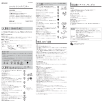
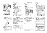
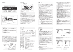
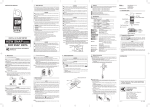
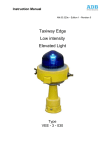
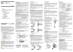
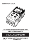
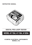
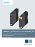
INSTRUCTION MANUAL
1. Safety Warnings
This instrument has been designed and
tested according to IEC Publication 61010:
Safety Requirements for Electronic
Measuring Apparatus. This instruction
manual contains warnings and safety rules
which must be observed by the user to
ensure safe operation of the instrument and
retain it in safe condition. Therefore, read
through these operating instructions when
using the instrument.
WARNING
Read through and understand instructions
contained in this manual when using the
instrument.
AC CLAMP METER
WITH DC VOLT RANGE
Save and keep the manual handy to enable
quick reference whenever necessary.
KEW SNAP 6
Be sure to use the instrument only in its
intended applications and to follow
measurement procedures described in the
manual.
KEW SNAP 2608A
Easy to use and dependable, the instrument is especially
designed to incorporate as many safety features as possible.
TRANSFORMER JAW
BARRIER
V TERMINAL
JAW TRIGGER
COM TERMINAL
RANGE SWITCH
OHM TERMINAL
POINTER LOCK BUTTON
ZERO ADJUSTER�
OHM
ZERO ADJUSTER
SCALE PLATE
WRIST STRAP
Be sure to understand and follow all safety
instructions contained in the manual.
Failure to follow the above instructions
may cause injury, instrument damage
and/or damage to equipment under test.
The symbol indicated on the instrument
means that the user must refer to related
parts in the manual for safe operation of the
instrument. Be sure to carefully read the
instructions following each symbol in
this manual.
DANGER:is reserved for conditions
and actions that are likely to cause serious
or fatal injury.
WARNING :is reserved for conditions
and actions that can cause serious or fatal
injury.
CAUTION:is reserved for conditions
and actions that can cause injury or
instrument damage
Following symbols are used on the
instrument and in the instruction manual.
Attention should be paid to each symbol to
ensure your safety.
Refer to the instructions in the manual.
This symbol is marked where the user
must refer to the instruction manual so as
not to cause personal injury or instrument
damage.
Indicates an instrument with double or
reinforced insulation.
Indicates that this instrument can clamp
on bare conductors when measuring a
voltage corresponding to the applicable
Measurement category, which is marked
next to this symbol.
Indicates AC (Alternating Current).
Indicates DC (Direct Current).
Indicates AC and DC.
DANGER
Never make measurement on a circuit
above 600V AC.
Do not attempt to make measurement in
the presence of flammable gasses, fumes,
vapor or dust. Otherwise, the use of the
instrument may cause sparking, which can
lead to an explosion.
Transformer jaw tips are designed not to
short the circuit under test. If equipment
under test has exposed conductive parts,
however, extra precaution should be taken
to minimize the possibility of shorting.
Never attempt to use the instrument if its
surface or your hand is wet.
Do not exceed the maximum allowable
input of any measurement range.
Never open the battery compartment
cover when making measurement.
Never try to make measurement if any
abnormal conditions, such as broken
Transformer jaws or case is noted.
The instrument is to be used only in its
intended applications or conditions.
Otherwise,safety functions, equipped with
the instrument doesn t work, and
instrument damage or serious personal
injury may be caused.
WARNING
Never attempt to make any measurement, if
the instrument has any structural
abnormality such as cracked case and
exposed metal part.
Do not install substitute parts or make any
modification to the instrument. Return the
instrument to Kyoritsu or your distributor for
repair or re-calibration.
Do not try to replace the batteries if the
surface of the instrument is wet.
Remove the test leads from the instrument
before opening the bottom case for battery or
fuse replacement.
KYORITSU
ELECTRICAL INSTRUMENTS WORKS, LTD
3. Specifications
Measuring Range and Accuracy
Ranges
Accuracy
AC current
6/15/60/150/300A
±3% of full scale
AC voltage
150/300/600V
±3% of full scale
DC voltage
60V
±3% of full scale
Resistance
x1Ω 1kΩ
(25Ω mid-scale)
x10Ω 10kΩ
(250Ω mid-scale)
-20-+150℃
Temperature (with optional
7060)
±2% of scale length
4. Preparation for Measurement
5. Measurement
4−1 Releasing Pointer Lock
Slide the pointer lock button to the right
position to unlock the pointer.
5−1 AC Current Measurement
4−2 Meter Zero Adjustment
Set the pointer at the center of the
“0”mark on the scale by rotating the zero
adjuster with a screw driver.
±5℃(0-+100℃)
Model ±10℃
(other ranges)
Overload Protection
Range
Maximum overload
AC6/15A
60A AC for 10 sec
AC60/150A
300A AC for 10 sec
AC300A
360A AC for 10 sec
AC150/300V
600V AC for 10 sec
AC600V
720V AC for 10 sec
DC60V
230V AC for 10 sec
×1Ω/×10Ω
230V AC, protection by fuse
Location for use
Conductor Size
Safety Standard
Withstand Voltage
Dimensions
Weight
PowerSource
Accessories
(included)
(optional)
POINTER
ZERO
ADJUSTER
:Indoor use, Altitude up to
2000m
Storage Temperature
and Humidity
:-10-+50℃,relative humidity up
to 75% without condensation
Operating
Temperature
and Humidity
POINTER LOCK
BUTTON
:0-+40℃, relative humidity up
to 90% without condensation
:Approx. 33mm diameter max.
:IEC61010-1 CAT.III 300V
CAT.II 600V
IEC61010-2-031
IEC61010-2-032
:3700V AC for 1 minute
between electrical circuit and
housing cases or metal parts of
jaws
:193(L) × 78(W) × 39(D)mm
:Approx.275g(battery included)
:R6P(DC1.5V)
battery
or
equivalent
:Instruction manual
Carrying case Model 9052
Test leads Model 7066
R6P battery(included within
the instrument)
Two 0.5A/250V
600V fuses(spare
fuse included)
:Model 8004,8008(Multi-Tran)
Model7060(temperature
probe)
4−3 Checking Battery Voltage
a. Set the range switch to the “×1Ω”
position.
b. Insert the red test lead into the OHM
terminal and the black test lead to the
COM terminal.
c. With the test leads shorted, try to set the
pointer over the “0” mark at the right end
of the resistance scale, using the OHM
zero adjuster.
d. When the adjustment brings the pointer
over the “0” mark, proceed to
measurement. If not, replace the battery.
(See section 7 for battery and fuse
replacement.)
NOTE
・The battery is needed only in resistance
measurement. AC/DC voltage and AC
current measurement can be made
without the battery.
・If the instrument does not operate
properly even after battery replacement,
check the fuse and test leads.
WARNING
・Do not make measurement on a circuit
above 600V AC. This may cause shock
hazard or damage to the instrument or
equipment under test.
・Transformer jaw tips are designed not
to short the circuit under test. If
equipment under test has exposed
conductive parts, however, extra
precaution should be taken to minimize
the possibility of shorting.
・Do not make measurement with the
bottom case removed.
・Do not make current measurement with
the test leads connected to the
instrument.
・Do not measure current exceeding the
limit for the overload protection feature.
・Keep your fingers and hands behind the
barrier during measurement.
CAUTION
・When the order of the current under
test is not known, make measurement
first on the highest 300A range, then
switch to the appropriate range.
a. Set the range switch to the “AC 300A”
position.
b. Press the trigger to open the transformer
jaws and clamp onto one conductor only.
It is recommended that the conductor be
placed at the center of the closed jaws.
CORRECT
WRONG
CAUTION
Make sure that the range switch is set to an
appropriate position before making measurement.
Always make sure to insert the plug of each test
lead fully into the appropriate terminal on the
instrument.
When the instrument will not be in use for a
long period of time, place it in storage after
removing the batteries.
Do not expose the instrument to the direct sun,
extreme temperatures or dew fall.
Use a damp cloth and detergent for cleaning
the instrument. Do not use abrasives or solvents.
○Measurement categories(Over-voltage categories)
To ensure safe operation of measuring
instruments, IEC61010 establishes safety
standards for various electrical environments,
categorized as CATⅠto CATⅣ, and called
measurement categories.
Higher-numbered categories correspond to
electrical environments with greater momentary
energy, so a measuring instrument designed for
CATⅢ environments can endure greater
momentary energy than one designed for CATⅡ
CAT.Ⅰ: Secondary electrical circuits connected to
an AC electrical outlet through a
transformer or similar device.
CAT.Ⅱ: Primary electrical circuits of equipment
connected to an AC electrical outlet by a
power cord.
CAT.Ⅲ: Primary electrical circuits of the equipment
connected directly to the distribution
panel, and feeders from the distribution
panel to outlets.
CAT.Ⅳ: The circuit from the service drop to the
service entrance, and to the power meter
and primary over-current protection
device(distribution panel).
Incoming wire
Interior wiring
CAT.Ⅲ
CAT.Ⅳ
Transformer
CAT.Ⅰ
Socket
CAT.Ⅱ
2. Features
Tear-drop-shaped jaws for ease of use in
crowded cable areas and other tight places
Safety design throughout. Designed to CAT.III
300V/CAT.II 600V and pollution degree 2
specified by the international safety standard
IEC 61010.
DC voltage range especially useful for
checking a power supply for emergency use
Pointer lock feature for easy reading in dimly
light or hard-to-read locations
Uses shrouded transformer jaws to further
improve safety
Optional temperature probe for temperature
measurement
c. Take the reading on the 300A current
scale.
d. Set the range switch to the appropriate
position based on the reading.
e. Take the reading on the appropriate scale.
Range
Scale used
Multiply reading by
AC6A
60A
×0.1
AC15A
150A
×0.1
AC60A
60A
×1
AC150A
150A
×1
AC300A
300A
×1
NOTE
・During current measurement, keep the
transformer jaws fully closed. Otherwise,
accurate measurement cannot be made.
The maximum conductor size is 33mm in
diameter.
・When measuring a larger current, the
transformer jaws may buzz. This is not a
fault and does not affect the accuracy at
all.
5-2 AC Voltage Measurement
WARNING
・Do not make measurement on a circuit
above 600V AC. This may cause shock
hazard or damage to the instrument or
equipment under test.
・Do not make measurement with the
bottom case removed.
・Do not apply to the instrument voltage
exceeding the limit for the overload
protection feature.
・Keep your fingers and hands behind the
barrier during measurement.
a. Set range switch to an AC voltage
position. When the order of the voltage
under test is not known, set the range
switch to the highest 600V range.
b. Insert the red test lead to the V terminal
and the black test lead to the COM
terminal.
c. Connect the tip of the test leads to the
circuit under test.
CAUTION
・Make sure to remove the test leads
from the terminals when resistance
measurement is over. If the test leads
are left inserted to the terminals, their
inadvertent shorting can exhaust the
battery.
BLACK
TEST LEAD
d. Take the reading on the scale for the
selected range.
e. After completing the measurement,
remove the test leads from the circuit
under test.
Range
Scale used
Multiply reading by
AC150V
150V
×1
AC300V
300V
×1
AC600V
60V
×10
a. Set the range switch to the “×1Ω” or “×
10Ω” position.
b. Insert the red test lead to the OHM
terminal and the black test lead to the
COM terminal.
c. With the test leads shorted, set the
pointer over the “0” mark at the right end
of the resistance scale, using the OHM
zero adjuster.
WARNING
・Do not make measurement with the
bottom case removed.
・Make sure that there is no voltage in
the circuit or equipment under test.
・Keep your fingers and hands behind the
barrier during measurement.
7−2 Fuse Replacement
The instrument s resistance measuring
circuit is protected by a 0.5A/250V
600V fuse.
When the instrument does not operate
properly in resistance measurement,
check the fuse and replace it in the
following steps, when necessary.
a. Remove the test leads from the
instrument.
b. Remove the screw on the back side of the
bottom case to open the instrument.
c. Replace the blown fuse with the spare
fuse installed beneath the battery.
d. Screw the bottom case back onto the
instrument.
a. Make AC current, AC voltage, DC voltage
or resistance measurement as described
in section 5.
POINTER LOCK
BUTTON
WARNING
・To avoid electric shock hazard, make
sure to remove the test leads from the
instrument before trying to replace
batteries.
・Make sure to screw the bottom case
back onto the instrument after battery
or fuse replamement.
・Do not install a battery or fuse that does
not have the specified rating.
SCREW
LOCK
RELEASE
WARNING
・Do not make measurement on a circuit
above 60V DC.
・Do not make measurement with the
bottom case removed.
・Keep your fingers and hands behind the
barrier during measurement.
5−4 Resistance Measurement
7. Battery and Fuse Replacement
The pointer lock feature can be used for
measurement in dimly light or hard-to-read
locations.
BLACK TEST LEAD
5−3 DC Voltage Measurement
a. Set range switch to the “DC
60V”position.
b. Insert the red test lead to the V terminal
and the black test lead to the COM
terminal.
c. Connect the red test lead tip to the
positive side of the circuit under test and
the black test lead tip to the negative
side.
d.Take the reading on the 60V scale.
e. After completing the measurement,
remove the test leads from the circuit
under test.
6. Using Pointer Lock
b. Slide the pointer lock button to the left
position.
c. Take the reading away from the
conductor or the circuit under test.
d. To release the pointer lock, slide the
button to the right.
RED TEST LEAD
d. Connect the tip of the test leads to the
circuit under test.
e. Take the reading on the resistance scale
and multiply it as follows.
Range
Scale used Multiply reading by
×1Ω
Ω
×1
×10Ω
Ω
×10
8. Optional Accessaries
Model 8004 and 8008 (Multi-Trans)
Multi-Trans extend existing current
measuring range up to 3000A as well as the
maximum conductor size.
WARNING
・Do not make measurement on a circuit
above 600V AC.
・The transformer jaws are made of metal
and their tips are not insulated. Never
touch the exposed metal parts under
test with jaw tips.
・Do not make measurement with the
bottom case removed.
・Do not make measurement with the test
leads connected to the instrument.
a. Set the range switch to the “TEMP (×10Ω)”
position.
b. Insert the red test lead to the OHM
terminal and the black test lead to the
COM terminal.
c. With the test leads shorted, set the
pointer over the “0” mark at the right end
of the resistance scale, using the OHM
zero adjuster.
d. Remove the test leads from the terminals.
e. Insert Model 7060’s red plug to the OHM
terminal and the black plug to the COM
terminal.
f. Touch the tip of the temperature probe to
the part under test.
g. Wait until the reading become stable,
then take the reading on the temperature
scale.
CAUTION
・When the order of the current under
test is not known, make measurement
first on the highest 300A range, then
switch to the appropriate range.
Model8004
Model8008
Max. conductor
Measuring Input to
size
range
output ratio
(mm in diameter)
AC0∼
φ60
10:1
1000A
AC0∼
φ100
10:1
3000A
Model 7060
Model 7060 is an temperature probe with a
measuring range from −20℃ to +150℃.
WARNING
Do not make measurement on a metal part
with a voltage more than 30V AC or 60V
DC.
FUSE
R6P BATTERY
7−1 Battery Replacement a. Remove the test leads from the
instrument.
b. Remove the screw on the back side of the
bottom case to open the instrument.
c. Replace the battery with a new R6P
battery or equivalent. The new battery
must be installed in the orientation
indicated inside the instrument.
d. Screw the bottom case back onto the
instrument.
保 証 規 定
保証期間中に生じました故障は、以下の場合除き無償で
修理いたします。
1.取扱説明書によらない不適切な取扱い、使用方法、保
管方法が原因で生じた故障
2.お買い上げ後の持ち運びや輸送の間に、落下させるな
ど異常な衝撃が加わって生じた故障
3.当社のサービス担当者以外の改造、修理、オーバーホ
ールが原因で生じた故障
4.火災、地震、水害、公害およびその他の天変地異が原
因で生じた故障
5.傷などの外観上の変化
6.その他当社の責任とみなされない故障
7.電池など消耗品の交換、補充
8.保証書のご提出がない場合
◎ご注意
当社で故障状態の確認をさせていただき、上記に該当
する場合は有償とさせていただきます。
輸送中に損傷が生じないように梱包を施し、当社修理
センターまたは取扱店宛にお送りください。
年月日
担当者
修理内容
保証書
a. Set the range switch to the desired position.
b. Clamp Kew Snap 2608A onto the pick-up coil
of Multi-Tran.
c. Clamp Multi-Tran onto the bus-bar or
conductor under test.
d. Take the reading on Kew Snap 2608A and
multiply it by 10.
Models
SPARE FUSE
LLLLLLLLLLLLLLLLLLLLLLLLLLLLLLLLLLLLLLLLLLLLLLLL
RED
TEST LEAD
型名MODEL2608A 製造番号
保証期間 ご購入日( 年 月 日)より1カ年間
9.After-sales Service
9−1 Sending for Repair
Make sure to provide description of the
failure and your name, address and telephone
number. Pack the instrument securely so that
it will not be damaged during transportation
and forward it to your distributor.
9−2 Periodic Calibration
In order to maintain measurement accuracy,
it is recommended that you forward the
instrument to Kyoritsu Repair Center for
calibration once every year.
NOTE:
Calibration is charged.
KYORITSU reserves the rights to change
specifications or designs described in this
manual without notice and without obligations.
KYORITSU ELECTRICAL
INSTRUMENTS
WORKS, LTD.
No.5-20,Nakane 2-chome, Meguro-ku,
Tokyo, 152-0031 Japan
Phone : 81-3-3723-0131
Fax : 81-3-3723-0152
URL : http://www.kew-Itd.co.jp
E-mail : [email protected]
Factories : Uwajima & Ehime
LLLLLLLLLLLLLLLLLLLLLLLLLLLLLLLLLLLLLLLLLLLLLLLL
04-10
9-09
92-1396D
92-1396C