1
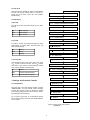
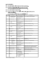
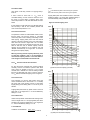
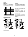
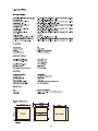
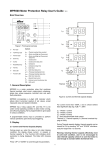
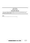
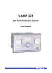
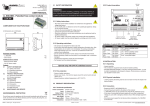
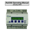
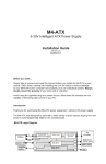
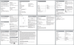
MPR500 Motor Protection Relay User's Guide
Brief Overview
h
i
Motor Protection Relay
a
b
c
t 6X
I>>
t >>
I <<
t <<
t
I o >>
t o >>
I S >>
t Start
t Stall
IB
CT
SW
IL1
d
e
f
g
IL2
IL3
I0
Thermal
1. General Description
MPR500 is a motor protection relay that combines
thermal overload, short circuit, undercurrent, unbalance,
phase loss, phase sequence, lock/stall rotor and earth
fault protections.
Figure 2: Current and thermal capacity display
MPR500 incorporates a 4-digit LED indicator which
allows direct numerical readout of set values, actual
measured value and system indication.
For current more than 1000A, a dot is shown behind
least significant digit. Eg: 1.25. = 1.25kA
MPR500 has 2 relay outputs (R1 and R2). R1 is On
under normal operating condition to allow motor running,
and off during tripping. R2 is programmable to give signal
in various conditions.
IL1 - Phase 1 current
IL2 - Phase 2 current
IL3 - Phase 3 current
I0 - Zero sequence/Earth fault current
Thermal % - Thermal capacity % (Thermal overload tripping at 100%)
A programmable binary input is provided to perform
various operations upon binary input triggering.
2. Display
During Thermal capacity display, thermal capacity can be
cleared to 0% by pressing "UP" and "DOWN" simultaneously for longer than 1.5 seconds.
2.1 Current and Thermal Capacity Display
During power up, when the relay is not under tripping
condition, the display shows current in ampere or
thermal capacity %. The Function LED indicates which
parameter is being displayed. The Data LED showing
value.
Warning: Clearing thermal capacity effectively reset
to cold start condition, user is not encouraged to
clear thermal capacity unless it is sure that motor is
cool enough to run/start within its thermal limit.
Press “UP” or “DOWN” to scroll through the parameters.
1
2.2 Auto Scroll
When auto scroll is enabled, the display scrolls between
currents and thermal reading every 10 seconds. To
toggle auto scroll mode, press "UP" and "DOWN"
simultaneously.
Current/Thermal Display
Tripping History
2.3 LED Display
a) Run LED
1 t6X Thermal overload time constant
Run LED shows the motor status. Refer to 3.2.1 Motor
Starting.
Off
Motor stopping
Blink
Motor starting
On
Motor running
2 I>> Short circuit
3 t>> Short circuit time delay
4 I<< Undercurrent
b) Trip LED
5 t<< Undercurrent time delay
Trip LED is normally off. During tripping pickup, where
tripping delay is counting down, Trip LED blinks. Trip
LED on during tripping.
Off
Normal
Blink
Pickup
On
Tripping
6
Unbalance
7 t
Unbalance time delay
8 I0 >> Earth fault
c) Thermal LED
9 t0 >> Earth fault delay
Thermal LED off when motor current is less than 105%
of IB. If motor current is more than 105% of IB, Thermal
LED blinks to give thermal overload warning. Thermal
LED on during thermal overload tripping.
A IS >> Prolonged starting / stalled rotor
Off
Normal
b t Start >> Prolonged starting time delay
Blink
Thermal overload warning
On
Thermal overload tripping
c t Stall >> Stalled rotor time delay
d IB Base/full load current
3. Settings and Protection Features
E External CT ratio
3.1 Setting Display
When the relay is not under tripping condition, pressing
"RESET/MODE" will scroll through various settings.
Function LED showing number or alphabet to indicate
which setting is being view as shown in Figure 3. Table 1
gives description of each setting.
F1 Auto/Manual Reset
Tip: To quickly jump back to current/thermal display
during setting display, press and hold "RESET/MODE"
for 1.5 second.
F3 Relay 2
F2 Binary input
Figure 3: Display mode when pressing
Reset/Mode
2
Setting
Function
Setting Range
1
t6X Thermal overload
time constant
1-40s. In steps of 0.1s
for 1-10s, in steps of
1s for 10-40s.
Time constant for thermal overload
2
I>> Short circuit
off, 2-12 x IB. In steps
of 1 x IB
Short circuit setting in multiples of IB
3
t>> Short circuit time
delay
0-25s. In steps of 0.1s
for 0-10s, in steps of
1s for 10-25s
Time delay for short circuit
4
I<< Undercurrent
off, 20-90% of IB . In
steps of 1%
Undercurrent setting in % of IB
5
t<< Undercurrent time
delay
0-60s. In steps of 0.1s
for 0-10s, in steps of
1s in 10-60s.
Time delay for undercurrent
Unbalance
off, 10-50%. In steps
of 1%
Phase unbalance setting in %
Unbalance time
delay
0-25s. In steps of 0.1s
for 0-10s, in steps of
1s for 10-25s.
Time delay for phase unbalance
6
Description
7
t
8
I0 > Earth fault
off, 10-60% of IB . In
steps of 1%
Earth fault setting in % of IB
9
t0 > Earth fault time
delay
0-25s. In steps of 0.1s
for 0-10s, in steps of
1s for 10-25s.
Time delay for earth fault
A
IS >> Prolonged starting
/stalled rotor
off, 2-12 x IB. In steps
of 0.1 x IB
Prolonged starting/stalled rotor setting in
multiples of IB
b
tStart>> Prolonged
starting time
delay
0-60s. In steps of 0.1s
for 0-10s, in steps of
1s for 10-60s.
Time delay for prolonged starting
c
tStall>> Stalled rotor
time delay
0-60s. In steps of 0.1s
for 0-10s, in steps of
1s for 10-60s.
Time delay for stalled rotor
d
IB Base/full load current 40-200% of IN
E
External CT ratio
1-200:1
External CT ratio. 1=direct.
F1
Auto/Manual Reset
0 - Manual reset
1- Auto reset
Manual or auto reset of tripping
Thermal overload is always auto reset
F2
Binary input
0 - Block relay 1
1 - Reset tripping
2 - Instant tripping
Setting for binary input
F3
Relay 2
0 - On any tripping
Relay 2 setting
1 - On thermal tripping
2 - On thermal
warning
Base/full load current of motor in % of relay
nominal current (IN is model dependent)
Table 1: Description of settings
3
3.2.1 Motor Status
where:
Upon power on the relay, if there is no tripping, Relay 1
turns on.
Imax is the maximum phase current among the 3 phases.
Imin is the minimum phase current among the 3 phases.
If motor current is more than 1.1 x IB, motor is
considered starting. If motor current is less than 1.05 x
IB, motor is running. Motor is stopping when motor
current drops below 0.1 x IB. RUN LED shows the motor
status.
Tripping takes place when unbalance value is more than
unbalance setting % for longer than unbalance delay. It
can be disabled by setting unbalance delay to 'off'.
Figure 4: Thermal tripping curve
If motor starts for longer than 60s, Run LED stop blinking
and off, Relay 1 also off. This condition persists until
motor current drops below 0.1 x IB.
time
2hour
3.2.2 Thermal Overload
1hour
The protection is based on mathematical model of motor
thermal image. The thermal capacity is calculated
continuously when motor is starting, overloading or even
after tripping. Tripping takes place when the thermal
capacity of the motor reaches 100%. This could happen
when the motor current is higher than 1.05 x IB. After
tripping a new start is not allowed until the motor cools
down to less than 40% of thermal capacity. Thermal
capacity can be cleared to 0% by pressing "UP" and
"DOWN" simultaneously for longer than 1.5 seconds
during thermal capacity display.
30min
20min
10min
5min
3min
2min
t6x
1min
40s
30s
Warning: Clearing thermal capacity effectively reset
to cold start condition, user is not encouraged to
clear thermal capacity unless it is sure that motor is
cool enough to run/start within its thermal limit.
40s
30s
20s
20s
10s
10s
5s
5s
3s
2s
2s
1.05
1s
3.2.3 t6X Thermal overload Time Constant
1s
1
t6X sets the themal overload time constant (heating
constant), which is the maximum period of time when
motor current is allowed to reach a 6 x IB. Cooling
constant time is defined as 4 times of heating constant
time and is applicable when motor current is less than
0.2 x IB. Refer to the thermal tripping curve on Figure 4.
2
3
4
5
6
(a) With 0% thermal capacity (cold start)
I/IB
time
2hour
1hour
3.2.4 Short Circuit
30min
This protection is to trip the relay quickly when high
current is detected due to short circuit. I>> is normally
set higher than motor starting current to avoid false
tripping during motor starting and t>> is set to very short
duration.
20min
10min
5min
3min
2min
Tripping takes place when any phase of motor current is
larger than I>> for longer than t>>. It can be disabled by
setting t>> to 'off'.
1min
40s
30s
3.2.5 Undercurrent
t6x
10s
40s
30s
20s
5s
10s
20s
Undercurrent protection is activated when average motor
current is larger than 0.1 x IB. Tripping takes place when
average motor current is smaller than I<< for longer than
t<<. It can be disabled by setting t<< to 'off'.
3s
5s
2s
3.2.6 Unbalance
1.05
1s
I
-I
Unbalance is calculated as: max min X 100 %
Imin
1
2s
1s
2
3
4
(b) With prior 50% thermal capacity
4
5
6
I/IB
3.2.7 Phase Loss
For example to use the relay that has nominal
current(IN) of 5A with motor that has full load current of
138A, using external CT of 150/5,
Phase loss fault is detected when average motor current
is larger than 0.28 x IB but any phase current is less than
0.1 x IB. Tripping takes place in less than 120ms when
phase loss is detected.
IB =
138
5
X
5
X 100 = 92 %
150
3.2.8 Phase Sequence
Phase sequence fault is detected when the phase
sequence in any 2 or all the phases are reversed.
Tripping takes place in less than 120ms when phase
sequence fault is detected.
3.2.12 External CT Ratio
If external CT is connected, the CT ratio shall be set
accordingly for the display to show correct current. For
example when using 150/5 CT, set the value to:
3.2.9 Prolonged Starting and Stalled Rotor
External CT ratio =
For prolonged starting and stalled rotor there is one IS>>
setting and separate time delay setting for each
protection. IS>> shall be set below the motor starting/
stalled current. These protections are useful when
thermal overload protection is not fast enough to protect
the motor during stalling.
Time delay for prolonged starting, tStart>> shall be set
longer than specified motor starting time. Tripping takes
place when any phase current is larger than IS> for
longer than tStart during motor starting.
Time delay for stalled rotor, tStall>> is activated upon
completing the motor starting. Tripping occurs when any
phase current is larger than IS>> for longer than tStall>>
during motor running.
Both protections can be disabled by setting IS>> to 'off'.
To disable only one of the protection, set the respective
time delay for the protection to be disabled to much
longer than specified.
3.2.10 Earth Fault
Earth fault protection is based on zero sequence current
calculation. Tripping takes place when the current is
larger than earth fault setting in % of IB for longer than
t0>. It can be disabled by setting t0>> to 'off'.
3.2.11 Base Current
Base current is the motor full load current. The range of
setting is model dependent. The formula is:
Motor full load current
IB =
Nominal relay current, IN
X 100 %
For example to use the relay that has nominal current
(IN) of 5A with motor that has full load current of 4.5A,
IB =
4.5
5
X 100 = 90 %
When external CT is used, the formula is:
IB =
Motor full load current
Nominal relay current, IN
X
1
X 100 %
CT ratio
5
150
= 30
5
4. Tripping
4.1 Tripping Display
4.2 Tripping Reset
During tripping, Trip LED on, Thermal LED also on
during thermal overload tripping. Function LED and Data
LED blinks showing tripping current or source as shown
below:
During tripping condition, press "RESET/MODE" to
reset, the relay will reset if condition permits. If relay is
set to auto reset, the relay will reset automatically if the
tripping condition is cleared with a 5% hysteresis.
Trip LED Thermal Function Data LED
LED
LED
4.3 Tripping Test
Description
On
On
t oL
On
Off
2 tripping current Short circuit tripping
On
Off
4 tripping current Undercurrent tripping
On
Off
6 Ub
Unbalance tripping
On
Off
6 PS
Phase sequence error
tripping
On
Off
6 PL
Phase loss tripping
On
Off
8 tripping current Earth fault tripping
On
Off
A tripping current Prolonged
starting/Stalled rotor
tripping
On
Off
t ESt
Trip Test
On
Off
t riP
Binary input tripping
Press "TEST" to simulate a tripping condition. "tESt" will
blink, R1 off and R2 on if set to "On any tripping". Press
"RESET/MODE" to reset.
Thermal Overload
tripping
4.4 Binary Input Tripping
When Binary input is set to 2 - Instant tripping, binary
input will generate a tripping condition. "triP" will blink,
R1 off and R2 on if set to "On any tripping". Press
"RESET/MODE" to reset. If relay is set to auto reset, the
relay will reset after the input is normal for 1s.
4.5 Tripping History Display
During Current/Thermal display, press "RESET/MODE"
to jump to Tripping History Display. Display shows the
previous tripping status with a 'dot' blinking at Function
LED. To clear tripping history, press "UP" and "DOWN"
simultaneously.
Table 2: Tripping display
5. Typical Application Diagram
L3 L2 L1
F1 F2
L3 L2 L1
F4
F1 F2
F3
MPR 500
K1
1
Aux
10
2
11
3
12
13
14
9
N
10
2
NO
11
3
NC
5
COM
6
COM
S2
8
M
2-10A
NC
13
5
14
6
COM
S2
Stop
Binary
input
K1
15
7
NC
16
8
NO
M
S1
Start
R2
NO
H1
NO
COM
K1
NC
Block R1/
Reset/
Trip
N
R1
S1
Start
L
4
12
Stop
7
1
Aux
4
R2
16
MPR 500
L
R1
15
F3
K1
9
Binary
input
F4
H1
K1
K1
Block R1/
Reset/
Trip
N
Motor with full load current of 2A to 10A
Motor with higher full load current using external CT
Figure 5: Example of application
6
N