1
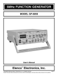
USER'S MANUAL
Sweep Function Generator
with Counter
SWF-8030
CIRCUIT-TEST ELECTRONICS
www.circuittest.com
TABLE OF CONTENTS
SAFETY INFORMATION ................................................................. page 3
INTRODUCTION....................................................................................... 4
SPECIFICATIONS .................................................................................... 5
FRONT PANEL DESCRIPTION . .............................................................. 8
OPERATING INSTRUCTIONS ............................................................... 10
MAINTENANCE . .................................................................................... 14
-2-
SAFETY INFORMATION
Caution and proper guidelines must be followed for personal and product safety. Read
this instruction manual carefully before using the instrument.
CAUTION:
This instrument can operate on 115VAC or 230VAC. Before connecting the AC power plug
to an AC line outlet, be sure to check that the voltage selector plug is set in the correct
position corresponding to the line voltage. The instrument may not operate properly or
may get damaged if it is connected to incorrect AC line voltage. Whenever line voltage
is changed, fuse must be replaced with appropriate correct value.
SELECTOR
LINE VOLTAGE
FUSE
230V
220~240V 50/60Hz
300mA
115V
100~125V 50/60Hz
600mA
This instrument has been designed for indoor use only. Operating temperature of this
instrument is 10°C to 40°C (50°F to 104°F). Operation outside of this temperature range
may cause damage to the circuits.
Do not use this instrument in a place where strong magnetic or electric fields exist. Such
fields may adversely affect the measurements.
If the instrument is used in a manner not specified by the manufacturer then protection
mechanisms built into the instrument may not function properly.
WARNING:
The following precautions must be observed to help prevent electric shock:
1. When the instrument is used to make measurements where high voltages are present, there is always a certain amount of danger from electrical shock. The person
using the instrument in such condition should be a qualified electronics technician
or otherwise trained and qualified to work in such circumstances.
2. The ground wire of the 3-wire AC power plug places the chassis and housing of the
instrument at earth ground. Use only a 3-wire outlet, and do not attempt to defeat
the ground wire connection or float the instrument, since doing so may pose a great
safety hazard.
3. Never apply external voltage to the output BNC of the instrument.
4. Excessive voltage applied to the input BNC may damage the instrument.
5. Do not operate the instrument with the cover removed unless by a qualified service
technician.
-3-
INTRODUCTION
DESCRIPTION
The SWF-8030 is a highly reliable 3 MHz sweep function generator combined with a
60MHz counter. Rugged and easy to use with many convenient features make it ideal
for the hobbyist, educational, manufacturing or R&D laboratories.
FEATURES:
Function Generator:
SWF-8030 provides 6 waveforms selected by rotary switch. Maximum output 20Vp-p
(No-load), and Minimum output 0.1Vp-p (No-load).
Pulse Generator:
SWF-8030 provides positive pulse and negative pulse output, Maximum output 20Vp-p
(No-load). Frequency is displayed by LEDs; pulse width is from 0.4s to 100ns ideal for
most Audio, Video and other basic electronic circuit applications.
Sweep Generator:
SWF-8030 provides linear sweep or log sweep selection switch to select the sweep
mode. Maximum sweep width is 1:100 and sweep speed is from 5sec to 10ms. The
SWF-8030 also provides VCF input and synchronous output function.
Frequency Counter:
The SWF-8030 has a 5-digit micro-controlled counter. SWF-8030 features auto ranging,
auto gate time, high resolution - 0.001Hz, high input impedance - 1MΩ, high bandwidth
- 0.2Hz ~ 60MHz. SWF-8030 also provides triggering features such as an adjustable
trigger ±2.5V with LED indicator, AC / DC selector, 100KHz filter, and input attenuator
- input x20 for 300Vrms high voltage signal. The unit will also display the frequency of
the signal produced by the function generator.
-4-
SPECIFICATIONS
1. GENERAL SPECIFICATIONS
Frequency:
Output Waveform:
Stability:
Power source:
Power Consumption:
0.5Hz ~ 3MHz with 5-digit LED display, Max. resolution
0.001Hz
Sine, Square, Triangle, Ramp, Positive Pulse and Negative
Pulse
0.1% ~ 15minutes after power on
0.2% ~ 24hrs after power on
AC 115V (±10%) 50/60HZ, FUSE: 600mA
AC 230V (±10%) 50/60HZ, FUSE: 300mA
25W
Operating Temperature: 0°C ~40°C, 10~80% R.H.
Storage Temperature:
-20°C ~70°C, 0~90% R.H.
Dimensions:
275 x 90 x 300 mm
Cooling:
Weight:
Accessories:
2. RAMP WAVE
DC 12V / 100mA Fan
2.5Kg Net
Power cord, Instruction Manual
Frequency:
0.5Hz ~ 2.5MHz, 5-digit LED display, Max. resolution 0.001Hz
Rise Wave Linearity:
< 2%, 1Hz - 100 KHz
Symmetry:
80% (Rise wave) to 20% (Fall wave), < 5%,
1Hz ~ 100 KHz
3. TRIANGLE WAVE
Frequency:
Symmetry:
4. SINE WAVE
0.5Hz ~ 3MHz, 5-digit LED display, Max. resolution 0.001Hz
50% (Rise wave) to 50% (Fall wave), < 2%,
1Hz ~ 100 KHz
Frequency:
0.5Hz ~ 3MHz, 5-digit LED display, Max. resolution 0.001Hz
Harmonic Ratio:
< 30dB, 100 KHz ~ 3MHz
Distortion:
Frequency Response:
< 2%, 1Hz ~ 100 KHz
< 0.1dB, up to 100 KHz
< 1dB, 100 KHz to 3MHz
-5-
SPECIFICATIONS
5. SQUARE WAVE
Frequency:
0.5Hz ~ 3MHz, 5-digit LED display, Max. resolution 0.001Hz
Rise Time:
< 60ns
Symmetry:
50% (Positive half) to 50% (Negative half). < 2%,
1Hz ~ 100 KHz
6. POSITIVE PULSE
Frequency:
0.5Hz ~ 2.5MHz, 5-digit LED display
Symmetry:
20% to 80%, < 5%, 1Hz ~ 100 KHz
Width:
Rise Time:
0.4sec ~ 100ns, continuous adjustment
< 60ns
7. NEGATIVE PULSE
Frequency:
0.5Hz ~ 2.5MHz, 5-digit LED display, Max. resolution 0.001Hz
Symmetry:
80% to 20%, < 5%, 1Hz ~ 100 KHz
Width:
Fall Time:
8. MAIN OUTPUT
Output Impedance:
Max. Output:
Min. output:
Attenuator:
0.4sec ~ 100ns
< 60ns
50Ω, < 2% Accuracy
20Vp-p (No load), ±1Vp-p
10Vp-p (50Ω load) ±0.5Vp-p
0.1Vp-p (No-load), or 0.05Vp-p (50Ω load)
One -20dB, < 2% Accuracy
9. SYNCHRONOUS OUTPUT
Output Impedance:
50Ω, < 2% Accuracy
Fan out:
> 20
Output Level:
Rise Time:
10. VCF INPUT
TTL level, > 3Vp-p fixed amplitude
< 30ns
Input Voltage:
0 ~ 10V
Input Frequency
Variance:
1:1 to 1:1000
Input Frequency:
DC ~ 1 KHz
-6-
SPECIFICATIONS
11. SWEEP SYNCHRONOUS OUTPUT
Output Impedance:
1 KHz, < 2%
Output Amplitude:
10Vp-p (No load) or 5Vp-p (1KΩ load)
Output Waveform:
Output Frequency:
Linear or Log Sweep Ramp Wave
0.2Hz ~ 100Hz, continuous adjustment
12. SWEEP GENERATOR
Sweep Form:
Linear or Log switchable
Sweep Width:
1:1 ~ 1:100
Sweep Speed:
13. COUNTER
5sec ~ 10ms, continuous adjustment
Display:
5 digits, 0.36" red LED display
Display unit:
Hz / KHz, Auto range
Max. Resolution:
0.001Hz
Time base:
20MHz
Accuracy:
< 0.002%
Temperature coefficient: < 10ppm / °C
Power Supply:
+5V, 160mA
INTERNAL COUNTER:
Range:
Display:
Gate time:
Min. display digits:
Auto range with 4 resolutions, 0.001Hz / 0.01Hz / 0.001
KHz/ 0.01KHz, auto controlled by CPU
0.500Hz ~ 3000.0 KHz, auto select by CPU
Variable, 0.25sec ~ 2sec, auto setting
4 digits
EXTERNAL COUNTER:
Max. Input Voltage:
< 250Vrms
Input Frequency:
0.2Hz ~ 60MHz
Input Impedance:
Coupling:
Min. display digits:
Gate Time:
Sensitivity:
1MΩ, < 2%
AC (HF) - For >100 KHz frequency
DC (LF) - With 100 KHz filter, for frequency <100 KHz
4 digits
0.25sec ~ 10sec, auto setting, depends on the input frequency
< 30mVrms (1MHz)
-7-
FRONT PANEL DESCRIPTION
1. POWER SWITCH - Push the switch "ON" and the LED digits (14) will light to indicate
power "ON".
2. FREQUENCY - Turn this knob to set the desired frequency generated. This knob is
for fine adjustment.
3. SYNC OUTPUT - Synchronous Output. A TTL level Square wave output with same
frequency as the Main output BNC.
4. SWEEP OUTPUT - Sweep signal output BNC. It will operate individually whether
the instrument was under sweep mode operation or not.
5. MAIN OUTPUT - Function wave output BNC. Output impedance is 50Ω, maximum
amplitude is 20Vp-p for no-load and 10Vp-p for 50Ω load.
6. AMPLITUDE - Turn the knob to adjust the output signal amplitude. Pull out the knob
to attenuate the output 10 times. This affects the Main output (5) signal only.
7. DC OFFSET - The knob controls the bias circuit, it is set at OFF position in normal
use. Pull "ON" and turn to adjust the DC offset voltage.
8. SWEEP RATE - Turn this knob to adjust the sweep rate from 5sec to 25ms, the sweep
output is BNC (4). If this knob is pulled out then the main output (5) and sweep output
(4) are synchronous.
9. SWEEP WIDTH - Turn this knob to adjust the sweep width. Push in for a linear sweep,
pull out for a log sweep. Knob (8) must be pulled out or this control is disabled.
10.FUNCTION WAVE SELECTOR - Turn this to select the output waveform.
11.FREQUENCY RANGE - Main adjustment of the frequency. The output frequency will
be 10 times on each step changed. The frequency of the output signal is the product
of the scale indicated by (2) and (11).
12.Hz - Lit LED means the display units are "Hz".
13.KHz – Lit LED means the display units are "KHz".
-8-
FRONT PANEL DESCRIPTION
14.LED DIGITS - 5 digits to indicate frequency generated or EXT input. The units will
be indicated by (12) or (13) selected by the CPU automatically.
15.EXT-TRIG - The green LED indicates trigger condition
LED Lit - Trigger level too high
LED Dark - Trigger level too low
LED Flashing - Triggering state
16.COUPLING - Indicates the source of the frequency display by (14).
INT - Displays the frequency of the signal generated.
EXT AC / HF - Displays the external input high frequency signal. Set at this position to strain out DC signal and low frequency harmonic signals. Input will be only
the expected high frequency signal.
EXT - DC / LF 100KHz Filter - Displays the external input low frequency signal.
Set at this position to strain out signals higher than 100 KHz and make the low
frequency signal more stable.
17.TRIGGER INPUT - Trigger level adjustment from +2V to -2V. When this knob is
pulled out the input signal will be attenuated 20 times, thus the input voltage can
be 250Vp-p Max.
18.EXT INPUT - External signal input BNC. Input frequency 0.2Hz to 60MHz and Max.
input voltage is 250Vp-p (when (17) is at "PULL" position).
19.VCF INPUT - External input DC signal used to control the frequency generated.
External input AC sweep signal to use it as an External sweep.
External input AC sine wave to use it as frequency modulation.
Input signal 0 ~ 10V, <1 KHz
Input impedance - 1KΩ.
-9-
OPERATING INSTRUCTIONS
WARNING:
Before applying power to SWF-8030, make sure correct input voltage has been
selected.
CAUTION:
All the knobs on the SWF-8030 are set at "push" position unless specially marked
"pull."
A. FUNCTION GENERATOR
1. Push the power switch on and make sure that the LEDs of the 5 digits are lit.
2. Connect OUTPUT BNC (4) of SWF-8030 to the CH1 input BNC of the oscilloscope,
and the SYNC OUTPUT BNC (5) to CH2, and set the trigger source of the oscilloscope at CH2.
3. Turn the FREQUENCY knob (6) from 0.05 to 3.0. The LED display and the oscilloscope waveform will change slightly on each step.
4. Turn the RANGE knob (7) from 10 to 1M. The LED display will change 10 times on
each step and the oscilloscope frequency will vary correspondingly.
5. Turn the FUNCTION knob (8) to select the waveform output to CH1 of the oscilloscope. CH2 will always be a TTL square wave.
6. Turn the AMPL knob (9) to adjust the amplitude of the signal output to CH1. Pull
out the knob, the amplitude of CH1 will be reduced 10 times (-20dB) but CH2 (Sync
output signal) will remain unchanged.
7. Turn the OFFSET knob (10), the display on the oscilloscope will be unchanged. Pull
out the knob. The display of CH1 on the oscilloscope will now be affected by the DC
offset voltage as controlled from +10V to -10V by turning the knob. The CH2 display
will be unaffected.
- 10 -
OPERATING INSTRUCTIONS
B. SWEEP GENERATOR
1. Switch on the SWF-8030 and the 5 digit LED display lights up.
2. Connect the main OUTPUT BNC (4) to the CH1 input BNC of the oscilloscope, the
SWEEP OUTPUT BNC (5) to CH2 input BNC of the oscilloscope and set the trigger
source of the oscilloscope at CH2.
3. Turn the SWEEP RATE (6), CH2 of the oscilloscope will display linear saw-tooth
wave, frequency can be varied from 5sec to 10mS. CH1 will display the wave according to the FUNCTION switch position. PULL out the knob to set "SWEEP ON". The
waveform of CH2 will remain unchanged, but the displayed frequency can be varied
by turning the frequency knobs. The display of CH1 will be a sweep wave, and the
sweep speed will depend on the sweep rate. NOTE: After "PULL SWEEP ON", the
trigger source of the oscilloscope must be changed from CH2 to CH1.
4. Turn the SWEEP WIDTH (7) to adjust the sweep width according to the display of
CH1. Set the FREQUENCY knob at 0.05 to have the maximum sweep width (>100
times). It is most commonly used when doing audio or circuit bandwidth testing.
PULL out knob, the sweep mode will change from linear sweep to Log sweep. The
waveform displayed on CH1 will be log form.
5. The AMPL (8) and FUNCTION (10) knobs will operate normally.
6. Before activating sweep mode the frequency displayed on the 5 LED digits is the
generator’s and this will be the start frequency. After "PULL SWEEP ON", the sweep
condition including frequency, waveform, and sweep mode etc. will be observed on
the CRT of the oscilloscope. The LED display on the SWF-8030 will vary continuously.
7. VCF INPUT (11) - Set the sweep rate switch at "PUSH" position to set SWF-8030 to
normal generator mode. Connect the sweep output BNC to VCF INPUT BNC and
check the waveform displayed on the scope CH1. The waveform displayed will be
the sweep wave. When the VCF input is a sine wave from another generator, the
SWF-8030 output will be frequency modulated. Be sure the frequency of the basic
wave (SWF-8030 output) is higher than the external input signal.
- 11 -
OPERATING INSTRUCTIONS
C. PULSE GENERATOR
1. Switch on the SWF-8030 and the 5 digit LED display lights up.
2. Connect the main OUTPUT BNC (3) to the CH1 input BNC of the Oscilloscope.
3. Connect the SYNC output (4) to CH2 and set the trigger source of the Oscilloscope
on CH2.
4. Set the "FUNCTION" knob (5) on a positive pulse position.
5. Set the FREQUENCY (7) and RANGE (6) to the desired frequency, displayed on
the LED (2).
6. Pulse width: the pulse width equals 15% of the total period of the output signal. If
the frequency is in Hz then the pulse width will be in sec. If the frequency is in KHz
then pulse width will be in mS etc.
EXAMPLE: If the frequency displayed is 1 KHz then the pulse width = 1/1 KHz *
15% = 0.15mS.
7. Set the FUNCTION knob on negative pulse position and similarly test the negative
pulse.
8. Turn the AMPL (9) to adjust the amplitude of the signal output from the main output
BNC (3). This signal will be -20dB when the knob (9) is pulled out. The signal output
from " SYNC " output BNC (4) will not be affected by this knob and will always be a
TTL level.
9. Set the DC offset voltage by pulling out the "OFFSET" knob (10) and turning it to
adjust the DC offset voltage from +10V to -10V as desired.
- 12 -
OPERATING INSTRUCTIONS
D. FREQUENCY COUNTER
1. Switch on the SWF-8030 and the 5 digit LED display lights up.
2. COUPLING (3): The frequency counter has 3 coupling options.
(a). INT - To be used with the internal function generator, 0.5Hz to 3MHz.
(b). EXT AC / HF: To be used with an external high frequency (100 KHz to 60MHz)
signal.
(c). EXT DC / LF: To be used with an external low frequency (0.2Hz to 100 KHz)
signal.
3. Connect the EXT INPUT BNC (4) to the external signal source.
4. Set the TRIG level (5) to meet the input signal. If the input signal is very large, pull
out the knob (PULL INPUT x20) to have stable counting. Max. input is 20Vp-p, or
600Vp-p with x20 engaged.
5. EXT TRIG'D (6) - The green LED will indicate the operating condition of the
SWF-8030.
LED LIT - the trigger level is higher than the input signal.
LED DARK - the trigger level is lower than the input signal.
LED FLASH - normal triggering.
Display unit (7): The SWF-8030 will be on Hz or KHz automatically controlled by the CPU.
- 13 -
MAINTENANCE
GENERAL MAINTENANCE
Clean and recalibrate the instrument on a regular basis to keep the instrument working well.
Never place heavy objects on the instrument.
Never place a hot soldering iron on or near the instrument.
Never insert wires, pins, or other metal objects into the ventilation fan.
Do not obstruct the ventilation holes in the rear panel, as this will increase the internal
temperature.
Never move or pull the instrument with the power cord or a probe cord. Never move
instrument when the power cord or a signal probe is connected to a circuit.
Remove any dirt, dust and grime whenever they become noticeable. Dirt on the outside
covers can be removed with a soft cloth moistened with a mild cleaning solution.
FUSE REPLACEMENT
If the fuse blows, the LED will not light and the instrument will not operate. Replace
only with the correct value fuse. The fuse is located on the rear panel adjacent to the
power cord receptacle.
Remove the fuse holder assembly as follows:
1. Unplug the AC power cord from rear of instrument.
2. Insert a small screwdriver in fuse holder slot (located between fuse holder and
receptacle) and pry the fuse holder away from receptacle.
3. When re-installing the fuse holder, make sure the fuse is installed so that the correct
line voltage is selected.
LIMITED WARRANTY
Circuit-Test Electronics warrants to the original purchaser that this product be free of
defect in material or workmanship for a period of 2 years from the date of purchase.
Any product which has been subjected to misuse or accidental damage is excluded
from the warranty. Except as stated above, Circuit-Test Electronics makes no promises
or warranties either expressed or implied including warranties of merchantability or the
fitness for any particular purpose.
M-SWF-8030 / 03R14
- 14 -