1
S950
PROGRAMMING MANUAL
PM94P01B
Copyright ©2005 by AC Technology Corporation.
All rights reserved. No part of this manual may be reproduced or transmitted in any form without written
permission from AC Technology Corporation. The information and technical data in this manual are subject to
change without notice. AC Tech makes no warranty of any kind with respect to this material, including, but not
limited to, the implied warranties of its merchantability and fitness for a given purpose. AC Tech assumes no
responsibility for any errors that may appear in this manual and makes no commitment to update or to keep
current the information in this manual.
MotionView®, PositionServo®, and all related indicia are either registered trademarks or trademarks of Lenze AG
in the United States and other countries.
This document printed in the United States of America
Table of Contents
1. Getting Started . . . . . . . . . . . . . . . . . . . . . . . . . . . . . . . . . . . . . . . . . . . . . . . . . . . . . . 3
1.1
1.2
1.3
1.4
1.5
1.6
1.7
1.8
1.9
1.10
1.11
1.12
Introduction . . . . . . . . . . . . . . . . . . . . . . . . . . . . . . . . . . . . . . . . . . . . . . . . . . . . . . . . . . . . . . . . . 3
Getting Started with the PositionServo . . . . . . . . . . . . . . . . . . . . . . . . . . . . . . . . . . . . . . . . . . . . 4
Programming Flowchart Overview . . . . . . . . . . . . . . . . . . . . . . . . . . . . . . . . . . . . . . . . . . . . . . . 5
MotionView / MotionView Studio . . . . . . . . . . . . . . . . . . . . . . . . . . . . . . . . . . . . . . . . . . . . . . . . 6
Programming Basics . . . . . . . . . . . . . . . . . . . . . . . . . . . . . . . . . . . . . . . . . . . . . . . . . . . . . . . . . .8
Using Advanced Debugging Features . . . . . . . . . . . . . . . . . . . . . . . . . . . . . . . . . . . . . . . . . . . 15
Inputs and Outputs . . . . . . . . . . . . . . . . . . . . . . . . . . . . . . . . . . . . . . . . . . . . . . . . . . . . . . . . . . 15
Events . . . . . . . . . . . . . . . . . . . . . . . . . . . . . . . . . . . . . . . . . . . . . . . . . . . . . . . . . . . . . . . . . . . . 20
Variables and Define Statement . . . . . . . . . . . . . . . . . . . . . . . . . . . . . . . . . . . . . . . . . . . . . . . . 22
IF/ELSE Statements . . . . . . . . . . . . . . . . . . . . . . . . . . . . . . . . . . . . . . . . . . . . . . . . . . . . . . . . . 23
Motion . . . . . . . . . . . . . . . . . . . . . . . . . . . . . . . . . . . . . . . . . . . . . . . . . . . . . . . . . . . . . . . . . . . . 23
Subroutines and Loops . . . . . . . . . . . . . . . . . . . . . . . . . . . . . . . . . . . . . . . . . . . . . . . . . . . . . . 28
2. Programming . . . . . . . . . . . . . . . . . . . . . . . . . . . . . . . . . . . . . . . . . . . . . . . . . . . . . . 29
2.1
2.2
2.3
2.4
2.5
2.6
2.7
2.8
2.9
2.10
2.11
2.12
2.13
2.14
2.15
2.16
2.17
Introduction . . . . . . . . . . . . . . . . . . . . . . . . . . . . . . . . . . . . . . . . . . . . . . . . . . . . . . . . . . . . . . . . 29
Variables . . . . . . . . . . . . . . . . . . . . . . . . . . . . . . . . . . . . . . . . . . . . . . . . . . . . . . . . . . . . . . . . . . 31
Arithmetic Expressions . . . . . . . . . . . . . . . . . . . . . . . . . . . . . . . . . . . . . . . . . . . . . . . . . . . . . . 32
Logical Expressions and Operators . . . . . . . . . . . . . . . . . . . . . . . . . . . . . . . . . . . . . . . . . . . . . 32
Bitwise Operators . . . . . . . . . . . . . . . . . . . . . . . . . . . . . . . . . . . . . . . . . . . . . . . . . . . . . . . . . . . 32
Boolean Operators . . . . . . . . . . . . . . . . . . . . . . . . . . . . . . . . . . . . . . . . . . . . . . . . . . . . . . . . . . 33
Comparison Operators . . . . . . . . . . . . . . . . . . . . . . . . . . . . . . . . . . . . . . . . . . . . . . . . . . . . . . . 33
System Variables and Flags . . . . . . . . . . . . . . . . . . . . . . . . . . . . . . . . . . . . . . . . . . . . . . . . . . . 33
System Variables Storage Organization . . . . . . . . . . . . . . . . . . . . . . . . . . . . . . . . . . . . . . . . . . 34
System Variables and Flags Summary . . . . . . . . . . . . . . . . . . . . . . . . . . . . . . . . . . . . . . . . . . .34
Control Structures . . . . . . . . . . . . . . . . . . . . . . . . . . . . . . . . . . . . . . . . . . . . . . . . . . . . . . . . . . 35
Scanned Event Statements . . . . . . . . . . . . . . . . . . . . . . . . . . . . . . . . . . . . . . . . . . . . . . . . . . . 38
Motion . . . . . . . . . . . . . . . . . . . . . . . . . . . . . . . . . . . . . . . . . . . . . . . . . . . . . . . . . . . . . . . . . . . . 39
System Status Register (DSTATUS register) . . . . . . . . . . . . . . . . . . . . . . . . . . . . . . . . . . . . . . 45
Fault Codes (DFAULTS register) . . . . . . . . . . . . . . . . . . . . . . . . . . . . . . . . . . . . . . . . . . . . . . . 46
Limitations and Restrictions . . . . . . . . . . . . . . . . . . . . . . . . . . . . . . . . . . . . . . . . . . . . . . . . . . . 47
Homing . . . . . . . . . . . . . . . . . . . . . . . . . . . . . . . . . . . . . . . . . . . . . . . . . . . . . . . . . . . . . . . . . . . 47
3. Language Reference . . . . . . . . . . . . . . . . . . . . . . . . . . . . . . . . . . . . . . . . . . . . . . . . 54
Appendix A. Complete list of variables. . . . . . . . . . . . . . . . . . . . . . . . . . . . . . . . . . . . . . 71
PM94P01B
Safety Information
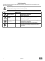
All safety information contained in these Operating Instructions is formatted with this layout including an icon,
signal word and description:
Signal Word! (Characterizes the severity of the danger)
Note (describes the danger and informs on how to proceed)
Signal Words
Icon
Warning of hazardous DANGER!
electrical voltage
Warns of impending danger.
Consequences if disregarded:
Death or severe injuries.
Warning of a general
danger
WARNING!
Warns of potential, very hazardous situations.
Warning of damage
to equipment
STOP!
Consequences if disregarded:
Death or severe injuries.
Warns of potential damage to material and equipment.
Information
Note
Consequences if disregarded:
Damage to the controller/drive or its environment.
Designates a general, useful note.
If you observe it, handling the controller/drive system is
made easier.
PM94P01B
1.
Getting Started
1.1
Introduction
Definitions
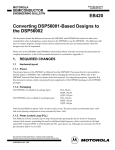
PositionServo: The PositionServo is a Programmable Digital Drive/Motion Controller, which can be configured
as a stand alone Programmable Motion Controller, or as a high performance Torque and Velocity Drive for
Centralized Control Systems. The PositionServo family of drives includes the 940 Encoder-based drive and the
941 Resolver-based drive.
MotionView: MotionView is a universal communication and configuration software package that is utilized by
the PositionServo drive family. It has an automatic self-configuration mechanism that recognizes what drive it is
connected to and configures the tool set accordingly. The MotionView platform is divided up into three sections
or windows, the “Parameter Tree Window”, the “Parameter View Window” and the “Message Window”. Refer to
Section 1.3 for more detail.
SimpleMotion Programming Language (SML): SML is the programming software utilized by MotionView. The
SML software provides a very flexible development environment for creating solutions to motion applications. The
software allows you to create complex and intelligent motion moves, process I/O, perform complex logic decision
making, do program branching, utilize timed event processes, as well as a number of other functions found in
PLC’s and high end motion controllers.
User Program (or Indexer Program): This is the SML program, developed by the user to describe the
programmatic behavior of the PositionServo drive. The User Program can be stored in a text file on your PC or in
the PositionServo’s EPM memory. The User Program needs to be compiled (translated) into binary form with the
aid of the MotionView Studio tools before the PositionServo can execute it.
MotionView Studio: MotionView Studio is a part of the MotionView software platform. It is a tool suite containing
all the software tools needed to program and debug a PositionServo. These tools include a full-screen text editor,
a program compiler, status and monitor utilities, an online oscilloscope and a debugger function that allows the
user to step through the program during program development.
WARNING!
•
•
Hazard of unexpected motor starting! When using the MotionView software, or otherwise
operating the PositionServo drive over RS-232/485 or Ethernet, the motor may start
unexpectedly, which may result in damage to equipment and/or injury to personnel. Make sure
the equipment is free to operate in this manner, and that all guards and covers are in place to
protect personnel.
Hazard of electrical shock! Circuit potentials are at 115 VAC or 230 VAC above earth ground.
Avoid direct contact with the printed circuit board or with circuit elements to prevent the risk of
serious injury or fatality. Disconnect incoming power and wait 60 seconds before servicing drive.
Capacitors retain charge after power is removed.
PM94P01B
1.2
Getting Started with the PositionServo
Before the PositionServo can execute a motion program the drive has to be properly installed and configured.
First time users are encouraged to read through the appropriate sections in this manual for the best configuration
of the PositionServo’s programmable features and parameters. They are also encouraged to reference the
PositionServo User’s Manual for the proper hardware installation.
The PositionServo drive has a number of features and parameters that can be programmed via the MotionView
Software. Below is a list of programmable features and parameters specific for operation under program control.
The features are listed in the order they appear in the ‘Parameter Tree Window” in MotionView. Please refer to
the PositionServo User’s Manual for details on parameters not covered herein.
Parameters
• Autoboot - Enable / Disable
If this option is Enabled, the drive will start executing the user program stored in the drive’s flash memory (i.e
EPM) at Power Up. If there is not a valid program existing in the flash memory, then the program must be started
manually via MotionView or a Host Interface.
DANGER!
Hazard of unexpected motor starting! When using the MotionView software, or otherwise operating
the PositionServo drive over RS-232/485 or Ethernet, the motor may start unexpectedly, which
may result in damage to equipment and/or injury to personnel. Make sure the equipment is free to
operate in this manner, and that all guards and covers are in place to protect personnel.
• Group ID
The Group ID feature allows the user to group PositionServo drives together via an Ethernet network. When
used with the SEND and SENDTO command, drives in the same group can share and update variables. Group
ID Numbers can be set between 0 and 32767. See statements SEND and SENDTO for further explanations.
Communication
• IP Setup - Displays properties and settings for Ethernet communication port (IP Address).
Digital I/O
• Inputs
- The PositionServo has 12 digital inputs. These inputs are grouped into three sets of four inputs, [A1 - A4 ],
[B1 - B4], and [C1 - C4]. Each group shares its own common, [Acom, Bcom, and Ccom].
- IN_A3 is dedicated as the ENABLE/DISABLE input for the drive.
- Inputs can be assigned individual debounce times via MotionView. Debounce times can be set between 0
and 1000ms. (1ms = 0.001 sec)
- Inputs can be monitored via the user program or via a host interface. Inputs can also be assigned Special
Purpose Functions. Refer to Section 1.6 for more detail.
• Outputs
- The PositionServo has 5 digital outputs. The first output is refered to as the ready output, RDY. This output
is a dedicated output and only comes on when the drive is enabled and in RUN mode. The remaining 4
outputs Out1, Out2, Out3 and Out4. can be activated via the user program or via a host interface. The se
outputs can also be assigned a Special Purpose Function. Refer to Section 1.6 for more detail.
Indexer Program
When the Indexer Program file is selected from the node tree, the Parameter View Window displays the
drive’s user program. This area can now be used to enter, edit and debug the user program. Also additional
programming features will be displayed in the menu and toolbar. Refer to Section 1.3 for more detail.
PM94P01B
1.3
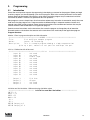
Programming Flowchart Overview
MotionView utilizes a BASIC-like programming structure referred to as SimpleMotion Programming Language
(SML). SML is a quick and easy way to create powerful motion applications.
With SML the programmer describes his system’s logistics, motion, I/O processing and user interaction using the
SML structured code. The program structure includes a full set of arithmetic and logical operator programming
statements, that allow the user to command motion, process I/O and control program flow.
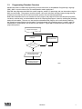
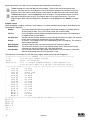
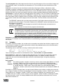
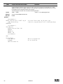
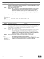
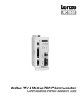
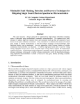
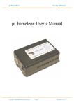
Before the PositionServo drive can execute the user’s program, the program must first be compiled (translated)
into binary machine code, and downloaded to the drive. Compiling the program is done by selecting the [Compile]
button from the toolbar. The user can also compile and download the program at the same time by selecting
the [Compile and Load] button from the toolbar. Once downloaded, the compiled program is stored in both the
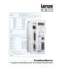
PositionServo’s EPM memory and the internal flash memory. Figure S801 illustrates the flow of the program
preparation process.
Prepare User Program
COMPILER
Fix program errors
Any Error?
YES
NO
Load compiled program
to PositionServo drive
Start Execution in
debugger environment
or at next power up
S801
PM94P01B
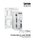
1.4
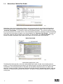
MotionView / MotionView Studio
mb802
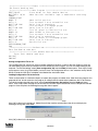
MotionView is the universal programming software used to communicate with and configure the SimpleServo
and PositionServo drives. The MotionView platform is segmented into three windows. The first window is the
“Parameter Tree Window”. This window is used much like Windows Explorer. The various parameters for the
drive are represented here as folders or files. Once the desired parameter file is selected, all of the corresponding
information for that parameter will appear in the second window, the “Parameter View Window”. The user can
then enable, disable or edit drive features or parameters. The third window is the “Message Window”. This
window is located at the bottom of the screen and will display all communication status and errors.
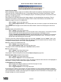
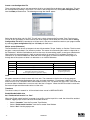
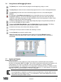
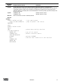
MotionView Studio
mb803
MotionView Studio Screen Layout
The MotionView Studio provides a tool suite used by MotionView to enter, compile, load and debug the user
program. To view and develop the user program, the “Indexer Program” file must be selected from the Parameter
Tree Window. Once selected the toolbar is expanded and two additional drop down menus are added to the
Menu Bar: “Indexer” and “Edit”. The program displayed in the View window is uploaded from the drive when the
connection is made between MotionView and the drive. This upload is always performed regardless of program
running state.
PM94P01B
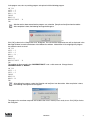
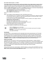
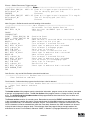
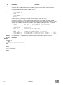
Studio Tool Suite Menu & Toolbar Options
mb804
Studio Tool Suite Menu
When developing or editing a program, the additional Menu option tabs [Indexer] and [Edit] become available.
These tabs are only available when the user is in the programming area (Parameter View Window). These
options are used to load, compile, save and debug the program. The following examples illustrate how to utilize
the Indexer and Edit option tabs.
Please note that to utilize these features the “Indexer program” must be selected from the node tree. This will
expand the menu options. Click the mouse anywhere in the Parameter View Window to activate Menu Tabs.
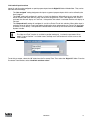
Load User program from the PC to MotionView
Select “Indexer” from the pull down menu.
Select “Import program from file” from the drop down menu and select a program from the folder where
it locates.
This procedure loads the program from the file to the editor window. It doesn’t load the program to the drive’s
memory.
-
-
Compile program and load to the drive
-
-
-
Select “Indexer” from the pull down menu.
Select “Compile and send to drive” from the drop down menu. If the program is successfully compiled
then the source code and the compiled bitstream will be loaded to the PositionServo drive.
or Select “Compile and load without source” from the drop down menu. If the program is successfully
compiled only the compiled bitstream will be loaded to the PositionServo drive. This feature is used to
prevent others from obtaining your source code.
To check syntax errors without loading the program to drive select “Compile” from the “Indexer” menu. If the
compiler finds any syntax error, compilation stops and program will not be loaded to the drive’s memory. Errors
are reported in bottom portion of the screen in Message Window.
Save User program from MotionView to PC .
- Select “Indexer” from the pull down menu.
- Select “Export program to file” from the drop down menu.
The program will be saved to the MotoinView “User Data” folder by default.
Run User program in drive.
-
-
Select “Indexer” from the pull down menu.
Select “Run” from the drop down menu.
If the program is already running, then you may need to Restart or Stop the program first.
Execute Program Step through the User program.
-
-
Select “Indexer” from the pull down menu.
Select “Step in / Step over” from the drop down menu.
The drive will execute the program one step at a time. The program statement under execution will be highlighted. If
the program is running, it will have to be either stopped or restarted.
Set Breakpoint(s) in the program
-
-
-
Select the point in the program where you would like the program to stop.
Select “Indexer” from the pull down menu.
Select “Toggle breakpoint” from the drop down menu.
A convenient way to debug a user program is to insert breakpoints at critical junctions throughout the program.
These breakpoints are marked by red dots and stop the drive from executing the program, but do not disable the
drive and the position variables. Once the program has stopped, the user can continue to run the program, step
through the program or restart the program.
PM94P01B
Stop program execution
-
-
Select “Indexer” from the pull down menu.
Select “Stop” from the drop down menu.
The program will stop after completing the current statement. Select Run to resume the program.
IMPORTANT!
The [STOP] button only stops the execution of the program code. It does not stop or disable the
motion.
Restart Program execution
-
-
Select “Indexer” from the pull down menu.
Select “Restart” from the drop down menu.
The program will be reset and the drive will be disabled. All the position variables will no longer be valid.
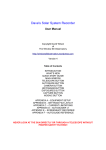
Studio Tool Suite Toolbar Options
When developing a User program, the MotionView Studio Toolbar becomes available. The toolbar provides
shortcuts to most of the options found in the Indexer Menu Option Tab. The toolbar is only available when you
are in the programming area (Parameter View Window). These options are used to load, compile, save and
debug the program.
Compile
Display Watch Window
Remove Breakpoint
Compile & Load with Source
Set Breakpoint
Run
Single Step (Step Into)
Reset Program
Stop Disable
Single Step (Step Over)
S805
MotionView Studio Toolbar Icons
1.5
Programming Basics
The user program consists of commands which when executed will not only initiate motion moves but also
process the drives I/O and make decisions based on drive parameters. Before motion can be initiated, certain
drive and I/O parameters must be configured. To configure these parameters perform the following procedure.
Parameter setup - Select “Parameter” from Parameter Tree Window and set the following parameters.
Set the “Drive” to “Position”.
- Select “Drive mode” from the Parameter View Window.
- Select “Position” from the pull down menu.
Set the “Reference” to “Internal”.
- Select “Reference” from the Parameter View Window.
- Select “Internal” from the pull down menu.
Set the “Enable switch function” to “Inhibit”.
- Select “Enable switch function” from the Parameter View Window.
- Select “Inhibit” from the menu.
I/O Configuration
Input A3 is the Inhibit/Enable special purpose input. Refer to section 4.1.7 for more information. Before executing
a program input A3 must be activated to enable the drive and take it out of Inhibit mode. Note: If the drive starts to
execute the user program and comes to an “Enable” command and input A3 is not made then the following fault
will occur “F_36”(“Drive Disable”).
Basic Motion Program
Select “Indexer program” from the Parameter Tree. The Parameter View Window will display the current User Program
stored in the drive. Note that if there is no valid program in the drive’s memory the program area will be empty.
PM94P01B
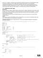
In the program area, clear any existing program and replace it with the following program:
UNITS=1
ACCEL = 5
DECEL = 5
MAXV = 10
ENABLE
MOVED 10
MOVEDISTANCE -10
END
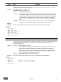
After the text has been entered into the program area, select the [Compile and load] icon from the toolbar.
After compilation is done, the following message should appear:
S806
Click [OK] to dismiss the “Compliation error” dialog box. The cause of the compilation error will be displayed in the
Message Window, located at the bottom of the MotionView window. MotionView will also highlight the program
line where the error occurred.
UNITS=1
ACCEL = 5
DECEL = 5
MAXV = 10 ;
ENABLE
;
MOVED 10
MOVEDISTANCE -10
END
The problem in this example is that “MOVEDISTANCE” is not a valid command. Change the text
“MOVEDISTANCE” to “MOVED”.
UNITS=1
ACCEL = 5
DECEL = 5
ENABLE
MOVED10
MOVED-10
END
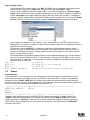
After editing the program, select the [Compile and load] icon from the toolbar. After compilation is done,
the following message box should appear.
S807
The program has now been compiled and loaded to the drive’s memory and is ready to run. Click [OK] to dismiss
the dialog box.
PM94P01B
Supose that the drive has been set up according to the PositionServo User Manual.
To Run the program, select the [Go] icon on the toolbar. The drive will start to execute the User
Program. The motor will spin 10 revolutions in the CCW direction and then 10 revolutions in the CW
direction. After all the code has been executed, the program will stop and the drive will stay enabled.
To Restart the program, select the [Restart] icon on the toolbar. This will disable the drive and reset
the program to execute from the start. The program does not run itself automatically. To run the
program again, either select the [Go] icon on the toolbar or select [Run] from the “Indexer” pull down
menu.
Program Layout
When developing a program, structure is very important. It is recommended that the program be divided up into
the following 7 segments:
Header:
I/O List:
Init & Set Var:
Events:
Main Program:
Sub-Routines:
Fault Handler:
The header defines the title of the program, who wrote the program and description of
what the program does. It may also include a date and revision number.
The I/O list defines what the inputs and outputs of the drive are used for. For example input
A1 might be used as a Start Switch.
Initialize and Set Variables defines the drives settings and system variables. For example
here is where acceleration, deceleration and max speed are set.
An Event is a small program that runs independently of the main program. This section is
used to define the Event.
The Main Program is the area where the process of the drive is defined.
This is the area where any and all sub-routines should reside. These routines will be
called out from the Main Program with a GO SUB command.
This is the area where the Fault Handler code resides. If a Fault handler is utilized this
code will be executed when the drive generates a fault.
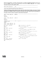
The following is an example of a Pick and Place program divided up into the above segments.
***************************** HEADER **************************************
;Title:
Pick and Place example program
;Author:
Lenze / AC Technology
;Description:
This is a sample program showing a simple sequence that
;
picks up a part moves to a set position and drops the part
;**************************** I/O List ************************************
;
Input A1 - not used
;
Input A2 - not used
;
Input A3 - Enable Input
;
Input A4 - not used
;
Input B1 - not used
;
Input B2 - not used
;
Input B3 - not used
;
Input B4 - not used
;
Input C1 - not used
;
Input C2 - not used
;
Input C3 - not used
;
Input C4 - not used
;
Output 1 - Pick Arm
;
Output 2 - Gripper
;
Output 3 - not used
;
Output 4 - not used
;********************** Initialize and Set Variables ***********************
UNITS = 1
ACCEL = 75
DECEL =75
MAXV = 10
;V1 =
;V2 =
10
PM94P01B
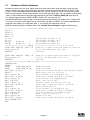
;********************** Events *********************************************
;Set Events handling here
;********************** Main Program **************************************
RESET_DRIVE:
;Place holder for Fault Handler Routine
WAIT UNTIL IN_3A: ;Make sure that the Enable input is made before continuing
ENABLE
PROGRAM_START:
;Move to Pick position
MOVEP 0
OUT1 = 1
;Turn on output 1 on to extend Pick arm
WAIT TIME 1000
;Delay 1 sec to extend arm
OUT2 = 1
;Turn on output 2 to Engage gripper
WAIT TIME 1000
;Delay 1 sec to Pick part
OUT1 = 0
;Turn off output 1 to Retract Pick arm
MOVED -10
;Move 10 REVs to Place position
OUT1 = 1
;Turn on output 1 on to extend Pick arm
WAIT TIME 1000
;Delay 1 sec to extend arm
OUT2 = 0
;Turn off output 2 to Disengage gripper
WAIT TIME 1000
;Delay 1 sec to Place part
OUT1 = 0
;Retract Pick arm
GOTO PROGRAM_START
END
;********************** Sub-Routines ***************************************
Enter Sub-Routine code here
;********************** Fault Handler Routine ********************
;
Enter Fault Handler code here
ON FAULT
ENDFAULT
Saving Configuration File to PC
The “Configuration File” consists of all the parameter settings for the drive, as well as the User Program. Once you
are done setting up the drive’s parameters and have written your User Program, you can save these setting to your
computer. To save the settings, select [Save configuration As] from the Node pull down menu. Then simply assign
your program a name, (e.g. Basic Motion), and click Save. The configuration file has a “dcf” extension and by default
will be saved to the “User Data” subfolder in the MotionView installation folder.
Loading Configuration File to the Drive There are times when it is desired to import (or export) the program to another drive. Other times the program was
prepared off-line. In both scenarios, the program or configuration file needs to be loaded from the PC to the drive.
To load the configuration file to the drive, select [Load configuration file to drive] from the Node pull down
menu. Then simply select the program you want to load and click Open. MotionView will first compile the selected
program. Once compiled, the following message box should appear.
S807
Click [OK] to dismiss this dialog box. MotionView will then load the selected file to the drive and display the
following message box when done.
S808
Click [OK] to dismiss the dialog box.
PM94P01B
11
Create a new Configuration File
There are times when you are not connected to the drive and would like to develop a new application. This may
be accomplished by loading a virtual drive. To create a new configuration file, select [New configuration file]
from the Node pull down menu. The following message box should appear.
S809
Select the desired drive and click [OK]. This will load a virtual drive onto the Parameter Tree. From here you
can set all your parameters as well as create your User Program. When done you can use the above “Saving
Configuration File to PC” procedure to save your work. Later you can continue to work on your program offline
by selecting [Open configuration file] from the Node pull down menu.
Motion source (Reference)
The PositionServo can be set up to operate in one of three modes: Torque, Velocity, or Position. The drive must
be given a command before it can initiate any motion. The source for commanding this motion is referred to as
the “Reference”. With the PositionServo you have two ways of commanding motion, or two types of References.
When the drive’s command signal is from an external source, for example a PLC or Motion Controller, it is
referred to as an External Reference. When the drive is being given its command from the User program or
through one of the system variables it is referred to as an Internal Reference.
“Reference” Parameter Setting
Mode
External
Internal
Torque
Analog input AIN1
System variable “IREF”
Velocity
Analog input AIN1
System variable “IREF”
Position
Step/Direction Inputs
Master Encoder Pulse Train Inputs
User Program (Trajectory generator output)
User Program/Interface
(Trajectory generator)
Units
All motion statements in the drive work with User units. The statement on the first line of the test program,
UNITS=1, sets the relationship between User units and motor revolutions. For example, if UNITS=0.5 the
motor will turn 1/2 of a revolution when commanded to move 1 Unit. By default the “User Units” value under the
parameter folder in MotionView is used, not set in the User’s Program. When the UNITS variable is set to zero,
the motor will operate with encoder counts as User units.
Time base
Time base is always in seconds i.e. all time-related values are set in USER UNITS/SEC.
Enable/Disable/Inhibit drive
Set “Enable switch function” to “Run”.
When the “Enable switch function” parameter is set to Run, and the Input A3 is made, the drive will be enabled.
Likewise, toggling input A3 to the off state will disable the drive.
-
-
-
12
Select “Parameter” from the Parameter Tree Window.
Select “Enable switch function” from the Parameter View Window.
Select “Run” from the popup menu.
PM94P01B
Set “Enable switch function” to “Inhibit”.
In the above example the decision on when to enable and disable the drive is determined by an external device,
PLC or Motion controller. The PositionServo’s User Program allows the programmer to take that decision and
incorporate it into the drive’s program. By default the drive will execute the User Program whether the drive is
enabled or disabled, however if a motion statement is executed while the drive is disabled, the F36 fault will occur.
When the “Enable switch function” parameter is set to Inhibit, and Input A3 is on, the drive will be disabled and
remain disabled until the ENABLE statement is executed by the User Program.
-
-
-
Select “Parameter” from the Parameter Tree Window.
Select “Enable switch function” from the Parameter View Window.
Select “Inhibit” from the popup menu.
Faults
When a fault condition has been detected by the drive, the following events occur:
-
-
-
-
-
-
-
If the PositionServo drive is running the user program, the program execution will be stopped immediately.
If a fault handler routine was defined, its code starts executing. Refer to Fault Handler section. If there is
no fault handler, the user program will be terminated
A fault code will be written in the DFAULTS register and will be available to user’s program. Refer to
section 2.15 for a list of fault codes.
Dedicated “Ready” output will turn OFF.
Any output with assigned special function “fault” will turn ON.
Any output with assigned special function “ready/enabled” will turn OFF.
Enable LED located on drive’s front panel will turn OFF:
The fault code will be displayed on the front LED.
Clearing a fault condition can be done in one of the following ways:
-
-
-
-
Select the [Restart] icon from the toolbar.
Execute the RESUME statement at the end of the Fault Handler routine (see Fault Handler
Example ).
Send “Reset” command over the Host Interface.
Cycle power (hard reset).
Fault Handler
The Fault Handler is a code segment that will be executed when the drive is experiencing a fault. This allows
the program to recover from a fault rather than just disabling the drive. While the drive is executing the Fault
Handler Routine the drive is disabled and therefore will not be able to detect any additional faults that might
occur. Because of this and due to the limited number of executable commands which can be used within the
Fault Handler Routine, it is highly recommended that the user exits the Fault Handler Routine by executing a
“RESUME” statement and jumps to a code segment designated to recover the drive from the fault.
Without Fault Handler
To simulate a fault, restart the Pick and Place example program. While the program is running, switch the
ENABLE input IN_A3 to the off state. This will cause the drive to generate an F_36 fault (Drive Disabled) and put
the drive into Fault Mode. While the drive is in Fault Mode, any output on will remain on and any off output will
remain off. The program execution will stop and any motion moves will be terminated. In this example the Pick
and Place arm may not be in a desired location when the program goes into the fault mode.
With Fault Handler
Add the following code to your sample program. While the program is running, switch the ENABLE input IN_A3,
to the off state. This will cause the drive to generate an F_36 fault (Drive Disabled) and put the drive into a Fault
Mode. From this point the Fault Handler Routine will take over.
PM94P01B
13
F_PROCESS:
WAIT UNTIL IN_A4==1 ;Wait until reset switch is made
WAIT UNTIL IN_A4==0 ;and then released before
GOTO RESET_DRIVE
;returning to the beginning of the program
END
;*********************** Sub-Routines *****************************
Enter Sub-Routines here;
;*********************** Fault Handler Routine *****************************
;Statement starts fault handler routine
ON FAULT
;Motion stopped, drive disabled, and events no longer
;scanned while executing the fault handler routine.
OUT2 = 0
;Output 1 off to Disengage gripper.
;This will drop the part in the gripper
OUT1 = 0
;Retract Pick arm to make sure it is up and out of the way
RESUME F_PROCESS
;program restarts from label F_PROCESS
ENDFAULT ;fault handler MUST end with this statement
Note
The following statements can not be used inside the Fault Handler Routine:
- ENABLE
- WAIT UNTIL
- MOVE
- MOVED
- MOVEP
- MOVEDR
- MOVEPR
- MDV
- MOTION SUSPEND
- MOTION RESUME
- GOTO, GOSUB
- JUMP
- ENABLE
- VELOCITY ON/OFF
See section 2.1 for additional details and the Language Reference section for the statement
“ON FAULT/ENDFAULT”.
14
PM94P01B
1.6
Using Advanced Debugging Features
The [Restart] icon is used to restart the program from the beginning, acting as a reset.
The [Step into] icon allows the user to execute the program one line at a time, including Sub-Routines
The [Step over] icon allows the user to execute the program one line at a time, excluding SubRoutines.
By selecting the [Insert/Remove breakpoints] icon on the toolbar the user can insert breakpoints
throughout the program. The drive will execute the program line by line until it comes to one of the
breakpoints. At this point the program will stop, allowing the user to evaluate program variables, check
program branching or just check code execution.
To continue code processing, you can either Step through the program using the above procedure or
you can select the [Go] icon from the toolbar.
To open the Variable Debug Window, select the [Debug View] icon from the toolbar. The Debug
Window allows you to view the drive’s system and user variable as well as I/O status.
Use the left arrow key to add variables after selecting a variable.
Use the right arrow key to remove variables after selecting a variable.
Use the [Refresh] key to refresh variable values.
Note that variable values are refreshed manually when you click on the [Refresh] button or
automatically when the program stops, when a single step is completed or when a breakpoint is
encountered.
S810
1.7
Inputs and Outputs
Analog Input and Output
-
-
The PositionServo has two analog inputs. These analog inputs are utilized by the drive as System
Variables and are labeled “AIN1” and “AIN2”. Their values can be directly read by the User Program or via
a Host Interface. This value can range from -10 to +10 and correlates to ± 10 volts analog input.
The PositionServo has one analog output. This analog output is utilized by the drive as a System Variable
and is labeled “AOUT”. It can be directly written by the User Program or via a Host Interface. Its value can
range from -10 to +10 which correlates to ± 10 volts analog input.
Note
If an analog output is assigned to any special function from MotionView, writing to AOUT from the
User Program will not change its value. If an analog output is set to “Not assigned” then it can be
controlled by writing to the AOUT variable.
PM94P01B
15
Digital Inputs
-
-
-
-
-
The PositionServo has twelve digital inputs. These digital inputs are utilized by the drive for decision
making in the User Program. Some examples would be travel limit switches, proximity sensors, push
buttons and hand shaking with other devices.
Each input can be assigned an individual debounce time via MotionView. From the Parameter Tree,
select [IO]. Then select the [Digital Input] folder. The debounce times will be displayed in the Parameter
View Window. Debounce times can be set between 0 and 1000 ms (1ms = 0.001 sec).
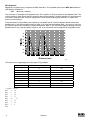
The twelve inputs are separated into three groups: A, B and C. Each group has four inputs and share
one common: Acom, Bcom and Ccom respectfully. The inputs are labeled individually as IN_A1 - IN_A4,
IN_B1 - IN_B4 and IN_C1 - IN_C4.
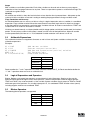
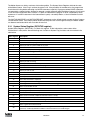
In addition to monitoring each input individually, the status of all twelve inputs can be represented as one
binary number. Each input corresponds to 1 bit in the INPUTS system variable. It is suggested that the
following format be used:
System Variable
INPUTS Bit #
11
10
9
8
7
6
5
4
3
2
1
0
Input Name
C4
C3
C2
C1
B4
B3
B2
B1
A4
A3
A2
A1
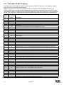
Some inputs can have additional special functionality such as Travel Limit switch, Enable input,
and Registration input. Configuration of these inputs is done from MotionView. Input functionality is
summarized in the table below and in the following sections. The status of the current state of the drive’s
inputs is available to the programmer through dedicated System Flags or as bits of the System Variable
INPUTS. The table below summarizes the serial functions for the inputs:
Function
Special function
Input A1
negative limit switch(1)
Input A2
positive limit switch(1)
Input A3
Inhibit/Enable input
Input A4
N/A
Input B1
N/A
Input B2
N/A
Input B3
N/A
Input B4
N/A
Input C1
N/A
Input C2
N/A
Input C3
Registration sensor input
Input C4
N/A
(1) Assume A1 is connected to the negative limit switch and A2 is connected tio the positive limit switch
16
PM94P01B
Read Digital Inputs
The Pick and Place example program has been modified below to utilize the “WAIT UNTIL” inputs statements in
place of the “WAIT TIME” statements. IN_A1 and IN_A4 will be used as proximity sensors to detect when the pick
and place arm is extended and when it is retracted. When the arm is extended, IN_A1 will be in an ON state and
will equal “1”. When the arm is retracted, IN_A4 will be in an ON state and will equal “1”.
;********************* Main Program ****************************************
RESET_DRIBVE:
;Place holder for Fault Handler Routine
WAIT UNTIL IN_3A
;Make sure that the Enable input is made before continuing
ENABLE
PROGRAM_START:
;Make sure Arm is retracted
WAIT UNTIL IN_A4==1 MOVEP 0
;Move to Pick position
OUT1 = 1
;Turn on output 1 to extend Pick arm
WAIT UNTIL IN_A1==1
; Arm extend
OUT2 = 1
;Turn on output 2 to Engage gripper
WAIT TIME 1000
;Delay 1 sec to Pick part
OUT1 = 0
;Turn off output 1 to Retract Pick arm
WAIT UNTIL IN_A4==1
;Make sure Arm is retracted
MOVED -10
;Move 10 REVs to Place position
OUT1 = 1
;Turn on output 1 on to extend Pick arm
WAIT UNTIL IN_A1==1
; Arm is extended
OUT2 = 0
;Turn off output 2 to Disengage gripper
WAIT TIME 1000
;Delay 1 sec to Place part
OUT1 = 0
;Retract Pick arm
WAIT UNTIL IN_A4==1
;Arm is retracted
GOTO PROGRAM_START
END
Once the above modifications have been made, export the program to file and save it as “Pick and Place with
I/O”, then compile, download and test the program.
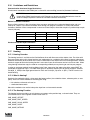
ASSIGN & INDEX - Using inputs to generate predefined indexes
“INDEX” is a variable on the drive that can be configured to represent a certain group of inputs as a binary
number. “ASSIGN” is the command that designates which inputs are utilized and how they are configured.
Below the Pick and Place program has been modified to utilize this “INDEX” function. The previous example
program simply picked up a part and moved it to a place location. For demonstration purposes we will add
seven different place locations. These locations will be referred to as Bins. What Bin the part is placed in will be
determined by the state of three inputs, B1, B2 and B3.
Bin 1
Bin 2
Bin 3
Bin 4
Bin 5
Bin 6
Bin 7
-
-
-
-
-
-
-
Input B1 is made
Input B2 is made
Inputs B1 and B2 are made
Input B3 is made
Inputs B1 and B3 are made
Inputs B2 and B3 are made
Inputs B1, B2 and B3 are made
The “ASSIGN” command is used to assign the individual input to a bit in the “INDEX” variable. ASSIGN INPUT
<input name> AS BIT <bit #>
;*********************** Initialize and
ASSIGN INPUT IN_B1 AS BIT 0
;Assign
ASSIGN INPUT IN_B2 AS BIT 1
;Assign
ASSIGN INPUT IN_B3 AS BIT 2
;Assign
Bin Location
Bin 1
Bin 2
Bin 3
Bin 4
Bin 5
Bin 6
Bin 7
Set
the
the
the
Variables *******************
Variable INDEX to equal 1 when IN_B1 is made
Variable INDEX to equal 2 when IN_B2 is made
Variable INDEX to equal 4 when IN_B4 is made
Input state
Input B1 is made
Input B2 is made
Inputs B1 and B2 are made
Input B3 is made
Inputs B1 and B3 are made
Inputs B2 and B3 are made
Inputs B1, B2 and B3 are made
PM94P01B
INDEX Value
1
2
3
4
5
6
7
17
The Main program has been modified to change the end place position based on the value of the “INDEX”
variable.
;************************** Main Program **********************************
ENABLE
PROGRAM_START:
WAIT UNTIL IN_A4==1
;Make sure Arm is retracted
MOVEP 0
;Move to (ABS) to Pick position
OUT1 = 1
;Turn on output 1 to extend Pick arm
WAIT UNTIL IN_A1==1
;Arm extends
OUT2 = 1
;Turn on output 2 to Engage gripper
WAIT TIME 1000
;Delay 1 sec to Pick part
OUT1 = 0
;Turn off output 1 to Retract Pick arm
WAIT UNTIL IN_A4==0
;Make sure Arm is retracted
IF INDEX==1
GOTO BIN_1
ENDIF
IF INDEX==2
GOTO BIN_2
ENDIF
.
.
.
IF INDEX==7
GOTO BIN_7
ENDIF
;In this area we use the If statement to
;check and see what state inputs B1, B2 & B3
;are in.
;
INDEX = 1 when input B1 is made
;
INDEX = 2 when input B2 is made
;
INDEX = 3 when input B1 & B2 are made.
;
INDEX = 4 when input B3 is made
;
INDEX = 5 when input B1 & B3 are made.
;
INDEX = 6 when input B2 & B3 are made.
;
INDEX = 7 when input B1, B2 & B3 are made
;We can now direct the program to one of seven
;locations based on three inputs.
BIN_1:
MOVEP 10
GOTO PLACE_PART
BIN_2:
MOVEP 20
GOTO PLACE_PART
BIN_7:
MOVEP 70
GOTO PLACE_PART
PLACE_PART:
OUT1 = 1
WAIT UNTIL IN_A4 == 1
OUT2 = 0
WAIT TIME 1000
OUT1 = 0
WAIT UNTIL IN_A4 == 0
GOTO PROGRAM_START
END
;Set up for Bin 1
;Move to Bin 1 location
;Jump to place part routine
;Set up for Bin 2
;Move to Bin 2 location
;Jump to place part routine
;Set up for Bin 7
;Move to Bin 7 location
;Jump to place part routine
;Turn on output 1 to extend Pick arm
;Arm extends
;Turn off output 2 to Disengage gripper
;Delay 1 sec to Place part
;Retract Pick arm
;Arm is retracted
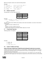
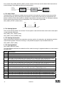
Note
Note: Any one of the 12 inputs can be assigned as a bit position within the INDEX variable. Only
bits 0 through 7 can be used with the INDEX variable. Bits 8-31 are not used and are always set to
0. Unassigned bits in the INDEX variable are set to 0.
BITS 8-31 (not used)
18
A1
0
A2
PM94P01B
A4
0
0
0
0
Limit switch input functions
Inputs A1 and A2 can be configured as special purpose inputs from the Digital I/O folder in MotionView. They can be
set to one of three settings:
-
-
-
The “Not assigned” setting designates the inputs as general purpose inputs which can be utilized by the
User Program.
The “Fault” setting will configure A1 and A2 as Hard Limit Switches. When either input is made the drive
will be disabled, the motor will hard stop, and the drive will generate a fault. If the negative limit switch is
activated, the drive will display an F-33 fault. If the positive limit switch is activated the drive will display an
F32 fault.
The “Stop and fault” setting will configure A1 and A2 as End of Travel limit switches. When either input is
made the drive will initiate a rapid stop before disabling the drive and generating an F34 or F35 fault (refer
to section 2.15 for details). The speed of the deceleration will be set by the value stored in the “QDECEL”
System Variable.
Note
The “Stop and Fault” function is available in position mode only, i.e. when the parameter “Drive
mode” is set to “Position”. In all other cases, the Stop and Fault function will act the same as the
Fault function.
S811
To set this parameter, select the “IO” folder from the Parameter Tree. Then select the “Digital IO” folder. From the
Parameter View Window, select “Hard limit switches action”.
PM94P01B
19
Digital Outputs Control
-
-
The PositionServo has 5 digital outputs. The “RDY” or READY output is dedicated and will only come on
when the drive is enabled, i.e. in RUN mode. The other outputs are labeled OUT1 - OUT4.
Outputs can be configured as Special Purpose Outputs. If an output is configured as a Special Purpose
Output it will activate when the state assigned to it becomes true. For example, if an output is assigned the
function “Zero speed”, the assigned output will come on when the motor is not in motion. To configure an
output as a Special Purpose Output, select the “IO” folder from the Parameter Tree. Then select the “Digital
IO” folder. From the Parameter View Window, select the “Output function” parameter you wish to set:
S812
-
-
-
OUT1
OUT2
OUT3
OUT2
1.8
Outputs which are configured as “Not assigned” can be activated either via the User Program or from a
host interface. If an output is assigned as a Special Purpose Output, neither the user program nor the host
interface can overwrite its status.
The Systems Variable “OUTPUTS” is a read/write variable which allows the User Program, or host
interface, to monitor and set the status of all four outputs. Each output allocates 1 bit in the OUTPUTS
variable. For example, if you set this variable equal to 15 in the User Program,i.e. 1111 in binary format,
then all 4 outputs will be turned on.
The example below summarizes the output functions and corresponding System Flags. To set the output,
write any non-0 value (TRUE) to its flag. To clear the output, write a 0 value (FALSE) to its flag. You can
also use flags in an expression. If an expression is evaluated as TRUE then the output will be turned ON.
Otherwise, it will be turned OFF.
= 1
;turn OUT1 ON
= 10
;any value but 0 turns output ON
= 0
;turn OUT3 OFF
= APOS>3 && APOS<10
;ON when position within window, otherwise OFF
Events
Scanned Events
A Scanned Event is a small program that runs independently of the main program. Scanned Events are very
useful when it is necessary to trigger an action, e.g. handle I/O, while the motor is in motion. In the following
example the Event “SPRAY_GUNS_ON” will be setup to turn Output 3 on when the drive’s position becomes
greater than 25. Note: the event will be triggered only at the instant when the drive position becomes greater than
25. It will not continue to execute while the position is greater than 25.
;*********************** EVENT SETUP ***************************************
EVENT SPRAY_GUNS_ON
APOS>25
OUT3=1
ENDEVENT
;***************************************************************************
The Event code should be entered in the EVENT SETUP section of the program. To Setup an Event, the
“EVENT” command must be entered. This is followed by the Event Name “SPRAY_GUNS_ON” and the
triggering mechanism, “APOS>25”. After that you can addd a sequence of programming events you wish to
occur once the event is triggered. In our case, we will turn on output 3. To end the Event, the “ENDEVENT”
command ust be used.
20
PM94P01B
Events can be activated, i.e. turned on, and deactivated, i.e. turned off, throughout the program. To turn on an
Event, the “EVENT” command is entered, followed by the Event Name “SPRAY_GUNS_ON”. This is trailed by
the desired state of the Event, “ON” or “OFF”.
;***************************************************************************
EVENT SPRAY_GUNS_ON
ON
;***************************************************************************
To learn more about Scanned Events refer to Section 2.12.
Two Scanned Events have been added to the Pick and Place program below to trigger a spray gun on and off.
The Event will be triggered after the part has been picked up and is passing in front of the spray guns (POS 25).
Once the part is in position, output 3 is turned on to activate the spray guns. When the part has passed by the
spray guns, (POS 75), output 3 is turned off, deactivating the spray guns.
;*********************** Events ********************************************
EVENT SPRAY_GUNS_ON
APOS>25
OUT3=1
ENDEVENT
EVENT SPRAY_GUNS_OFF APOS>75
OUT3=0
ENDEVENT
;*********************** Main Program **************************************
PROGRAM_START:
ENABLE
EVENT SPRAY_GUNS_ON ON
EVENT SPRAY_GUNS_OFF ON
WAIT UNTIL IN_A4==1
;Make sure Arm is retracted
MOVEP 0
;Move to Pick position
OUT1 = 1 ;Turn on output 1 to extend Pick arm
WAIT UNTIL IN_A1==1
;Arm extends
OUT2 = 1 ;Turn on output 2 to Engage gripper
WAIT TIME 1000
;Delay 1 sec to Pick part
OUT1 = 0 ;Turn off output 1 to Retract Pick arm
WAIT UNTIL IN_A4==1 ;Make sure Arm is retracted
MOVEP 100
;Move to Place position
OUT1 = 1 ;Turn on output 1 to extend Pick arm
WAIT UNTIL IN_A1==1
;Arm extends
OUT2 = 0 ;Turn off output 2 to Disengage gripper
WAIT TIME 1000
;Delay 1 sec to Place part
OUT1 = 0 ;Retract Pick arm
WAIT UNTIL IN_A4==1
;Arm is retracted
GOTO PROGRAM_START
END
PM94P01B
21
1.9
Variables and Define Statement
Variables are resources in the drive. Some of these variables can be read / write and some can be read only.
Certain variables are used to set the operating parameters of the drive, e.g. ACCEL, DECEL, or MAXV. Other
variables can be used to determine the status of the drive, e.g. AIN, INPUTS, or APOS. Variables can also be
used as system registers. These system registers can be local to the drive, (V01- V31), or network variables (NV0
- NV31). In the example below we set the trigger position for the EVENT “SPRAY_GUNS_ON” to be equal to
“V1”, and the trigger position for EVENT “SPRAY_GUNS_OFF” to be equal to “V2”.
The DEFINE command is used to assign a name to the state of a drive variable, e.g. Output_ON = 1, Output_OFF
= 0. You can also assign a meaningful name to a set number, e.g. MIN = 25, MAX = 75. In the example below we
assign the name “Output_On” to equal the value “1”, and “Output_Off” to equal the value “0”.
Defining and setting variables should be done in the “Initialize and set Variables” segment of the program.
;*********************** Initialize and Set Variables **********************
UNITS = 1
ACCEL = 5
DECEL = 5
MAXV = 10
;Set Variable V1 equal to 25
V1 = 25
V2 = 75
;Set Variable V2 euqal to 75
DEFINE
Output_On
1
;Define Name for output On
DEFINE
Output_Off
0
;Define Name for output Off
;*********************** EVENTS *******************************************
EVENT SPRAY_GUNS_ON
APOS > V1 ;Event will trigger as position passes 25 in pos dir.
OUT3= Output_On
;Turn on the spray guns (out 3 on)
ENDEVENT
;End event
EVENT SPRAY_GUNS_OFF APOS > V2 ;Event will trigger as position passes 75 in neg dir.
OUT3= Output_Off
;Turn off the spray guns (out 3 off)
ENDEVENT
;End even
;*********************** Main Program *************************************
PROGRAM_START:
ENABLE
EVENT
SPRAY_GUNS_ON ON
;Enable the Event
EVENT
SPRAY_GUNS_OFF ON
;Enable the Event
WAIT UNTIL IN_A4==1
;Ensure Arm is retracted before running the program
MOVEP 0
;Move to position 0 to pick part
OUT1 = Output_On
;Turn on output 1 to extend Pick arm
WAIT UNTIL IN_A1==1
;Check input to make sure Arm is extended
OUT2 = Output_On
;Turn on output 2 to Engage gripper
WAIT TIME 1000
;Delay 1 sec to Pick part
OUT1 = Output_Off
;Turn off output 1 to Retract Pick arm
WAIT UNTIL IN_A4==1
;Check input to make sure Arm is retracted
MOVED 100
;Move to Place position
OUT1 = Output_On
;Turn on output 1 to extend Pick arm
WAIT UNTIL IN_A1==1
;Check input to make sure Arm is extended
OUT2 = Output_Off
;Turn off output 2 to Disengage gripper
WAIT TIME 1000
;Delay 1 sec to Place part
OUT1 = Output_Off
;Retract Pick arm
WAIT UNTIL IN_A4==1
;Check input to make sure Arm is retracted
GOTO PROGRAM_START
END
22
PM94P01B
1.10 IF/ELSE Statements
An IF/ELSE statement allows the user to execute one or more statements conditionally. The programmer can use
an IF or IF/ELSE construct:
Single IF example:
This example increments a counter, Variable “V1”, until the Variable, “V1”, is greater than 10.
Again:
V1=V1+1
IF
V1>10
V1=0
ENDIF
GOTO Again
END
IF/ELSE example:
This example checks the value of Variable V1. If V1 is greater than 3, then V2 is set to 1. If V1 is not greater than
3, then V2 is set to 0.
IF V1>3
V2=1
ELSE
V2=0
ENDIF
Whether you are using an IF or IF/ELSE statement the construct must end with ENDIF keyword.
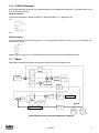
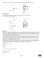
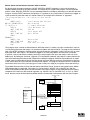
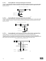
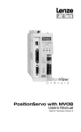
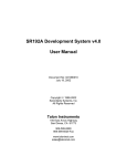
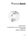
1.11 Motion
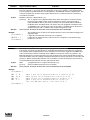
Figure S813 ilustrates the Position and Velocity regulator of the PositionServo drive.
Position Feedback
Kff term
P term
Position
Command
Current
limiter
D term
Biquad
covergence
filter
I term Limit and
unti wind-up
I term
Second
encoder Iterm
Current
limiter
P term
Biquad
convergence
filter
To Torque amplifier
Velocity
window
I term
I term Limit and
unti wind-up
Velocity
estimator
Mechanical Velocity feedback
Secondary
encoder
Primary
encoder
S813
PositionServo Position and Velocity Regulator’s Diagram
PM94P01B
23
The “Position Command”, as shown in the regulator’s diagram (S813), is produced by a Trajectory Generator.
The Trajectory Generator processes the motion commands produced by the User’s program to calculate the
position increment or decrement, also referred to as the “index” value, for every servo loop. This calculated target
(or theoretical) position is then supplied to the Regulator input.
The main purpose of the Regulator is to set the motors position to match the target position created by the
Trajectory Generator. This is done by comparing the input from the Trajectory Generator with the position
feedback from the encoder or resolver, to control the torque and velocity of the motor. Of course there will always
be some error in the position following. Such error is referred to as “Position Error” and is expressed as follows:
Position Error = Target Position - Actual Position
When the actual Position Error exceeds a certain threshold value a “Position Error limit”, fault (F_PE) will be
generated. The Position Error limit and Position Error time can be set under the Node Tree “Limits”/ “Position
Limits” in MotionView. The Position Error time specifies how long the actual position error can exceed the Position
Error limit before the fault is generated.
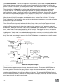
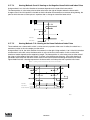
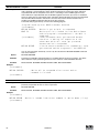
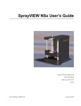
Drive Operating Modes
There are three modes of operation for the PositionServo, Torque, Velocity and Position. Torque and Velocity
modes are generally used when the command reference is from an external device, (Ain). Position mode is used
when the command comes from the drives User Program, or from an external device, encoder or a step and
direction pulse. Setting the drive’s mode is done from the “Parameter” folder in MotionView. To command motion
from the User Program the drive must be configured to Position Mode. Even though the drive is setup in position
mode, velocity mode can be turned on and off from the User Program. Executing the VELOCITY ON statement
is used to activate this mode while VELOCITY OFF will deactivate this mode. This mode is used for special case
indexing moves. Velocity mode is the mode when the target position is constantly advanced with a rate set in the
VEL system variable. Gear mode is the mode when the target position reference is fed from MA/MB inputs scaled
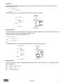
by the Gear Ratio (gear ratio set by statement Gear Ratio). The Reference arrangements for the different modes
of operation are illustrated in Figure S814.
#37, Reference
"INTERNAL"
MA/MB inputs
#214,#189 TPOS
Gearing
+
#79,#80
Master to System
ratio
+
POSITION
REGULATOR
+
Trajectory
Generator
User's program
Phase Correction
0 Torque
1 Velocity
#35,VELOCITY SCALE
#34, DRIVEMODE
2 Position
#89
Dead Band
Analog input #1
"INTERNAL"
1
1
#90, Offset
2
"INTERNAL"
3
VELOCITY
REGULATOR
2
3
CURRENT
REGULATOR
TO MODULAT
#36,CURRENT SCALE
IREF
S814
Reference Arrangement Diagram
Point To Point Moves
The PositionServo supports two types of moves, absolute and incremental. The statement MOVEP (Move to
Position) is used to make an absolute move. When executing an absolute move, the motor is instructed to move
to a known position. The move to this known position is always referenced from the motors “home” or “zero”
location. For example, the statement (MOVEP 0) will cause the motor to move to its zero or home position,
regardless of where the motor is located at the beginning of the move. The statement MOVED (Move Distance)
makes incremental, (or relative), moves from its current position. For example, MOVED 10, will cause the motor to
move forward 10 user units from it current location.
24
PM94P01B
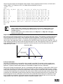
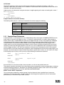
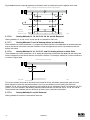
MOVEP and MOVED statements generate what is called a trapezoidal point to point motion profile. A trapezoidal
move is when the motor accelerates, using the current acceleration setting, (ACCEL), to a default top speed,
(MAXV), it then maintains that speed for a period of time before decelerating to the end position using the
deceleration setting, (DECEL). If the distance to be moved is fairly small, a triangular move profile will be used. A
triangular move is a move that starts to accelerate toward the Max Velocity setting but has to decelerate before
ever achieving the max velocity in order to reach the desired end point.
Trapezoidal Move Profile
Current accel value
Top Velocity
Triangular Move Profile
Velocity
Time
S815
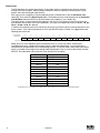
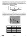
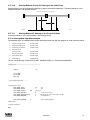
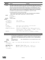
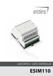
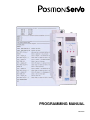
Segment moves
MOVED and MOVEP commands are simple and useful, but if the required move profile is more complex than a
simple trapezoidal move, then the segment move MDV can be used.
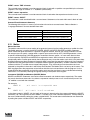
The profile shown below is divided up into 8 segments or 8 MDV moves. An MDV move (Move Distance Velocity)
has two arguments. The first argument is the distance moved in that segment. This distance is referenced from
the motors current position and is in User Units. The second argument is the desired target velocity for the end of
the segment move. That is the velocity at which the motor will run at the moment when the specified distance in
this segment is moved.
Velocity (RPS)
70
60
50
40
30
20
10
Segment
1
Segment
2
5
Segment
3
Segment
5
Segment
4
10
Segment
6
15
Segment
7
20
Segment
8
25
30
Distance (CM)
S816
Segment Number
Distance moved
during segment
Velocity at the end of
segment
1
3
56
2
3
12
3
4
16
4
2
57
5
2.5
57
6
3
11
7
5
20
8
5
0
-
-
-
PM94P01B
25
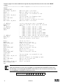
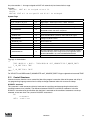
Here is the user program for the segment move example. The last segment move must have a “0” for the end
velocity, (MDV 5 , 0). Otherwise, fault F_24 (Motion Queue Underflow), will occur.
;Segment moves
LOOP:
WAIT UNTIL IN_A4==0 ;Wait until input A4 is off before starting the move
MDV 3 , 56
;Move 3 units accelerating to 56 User Units per sec
MDV 3 , 12
;Move 3 units decelerating to 12 User Units per sec
MDV 4 , 16
;Move 4 units accelerating to 16 User Units per sec
MDV 2 , 57
;Move 2 units accelerating to 57 User Units per sec
MDV 2.5 , 57
;Move 2.5 units maintaining 57 User Units per sec
MDV 3 , 11
;Move 3 units decelerating to 11 User Units per sec
MDV 5 , 20
;Move 5 units accelerating to 20 User Units per sec
MDV 5 , 0
;Move 5 units decelerating to 0 User Units per sec
WAIT UNTIL IN_A4==1 ;Wait until input A4 is on before looping
GOTO LOOP
END
Note
•
•
When an MDV move is executed, the segment moves are stored to a Motion Queue. If the
program loops on itself, then the queue will become full and an F_23 Fault Motion Queue
Overflow will occur.
Since the MDV moves utilize a Motion Queue, the “Step into” or “Step over” debugging
features can not be used.
Registration
Both absolute and incremental moves can be used for registration moves. The statements associated with these
moves are MOVEPR and MOVEDR. These statements have two arguments. The first argument specifies the
commanded move distance or position. The second argument specifies the move made after the registration
input is seen. If the registration move is an absolute move, (MOVEPR 10,30), then the second argument, “30”, will
simply define the position to move to after the registration input is made. If the registration move is an incremental
move, (MOVEDR 10,30), then the second argument will be the distance to move from the point where the
registration input is seen.
Registration Move
Position Registration
Input is made
Commanded
Move
Registration
Move
S817
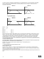
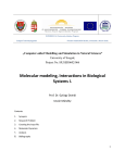
S-Curve Acceleration
Very often it is important for a move profile to be as smooth as possible. For example, using a smooth move
profile could minimize the wear and tear on a machine tool, proving critical to the successful completion of an
operation. To perform smooth motion profiles, the PositionServo supports S-curve acceleration.
With normal straight line acceleration, the axis is accelerated to the target velocity in a linear fashion. With S-curve
acceleration, the motor accelerates slowly at the first, then twice as fast as the middle straight line area, and then
slowly stops accelerating as it reaches the target velocity. With straight line acceleration, the acceleration changes
are abrupt at the beginning of the acceleration and again once the motor reaches the target velocity. With S-curve
acceleration, the acceleration gradually builds to the peak value then gradually decreases to no acceleration. The
disadvantage with S-curve acceleration is that for the same acceleration distance the peak acceleration is twice
that of straight line acceleration, which often requires twice the peak torque. Note that the axis will arrive at the
target position at the same time regardless of which acceleration method is used.
26
PM94P01B
T2
T1
T2
Velocity (RMS)
T1
Distance (Units)
S818
To use S-curve acceleration in a MOVED, MOVEP or MDV statement requires only the additional “,S” at the end
of the statement.
Examples:
MOVED 10 , S
MOVEP 10 , S
MDV
10,20,S
MDV
10,0,S
Motion Queue
The PositionServo drive executes the User Program one statement at a time. When a move statement (MOVED
or MOVEP) is executed, the move profile is stored to the Motion Queue. The program will, by default, wait or
hang on that statement until the Motion Queue has executed the move. Once the move is completed, the next
statement in the program will be executed. This will effectively suspend the program until the motion is complete.
A standard move (MOVED or MOVEP) is only followed by one argument. This argument references the distance
or position to move the motor to. By adding the second argument “C”, (MOVEP 0,C) or (MOVED 100,C), the drive
is allowed to continue executing the user program during the move. At this point, multiple move profiles can be
stored to the queue. The Motion Queue can hold up to 32 profiles. Like the EVENT command, the Continue “C”
argument is very useful when it is necessary to trigger an action, e.g. handle I/O, while the motor is in motion.
Below the Pick and Place Example Program has been modified to utilize the Continue, “C”, argument.
;**************************** Main Program ********************************
PROGRAM_START:
ENABLE
WAIT UNTIL IN_A4==1
;Make sure Arm is retracted before starting the program
MOVEP 0
;Move to position 0 to pick part
OUT1 = 1
;Turn on output 1 to extend Pick arm
WAIT UNTIL IN_A1==1
;Check input to make sure Arm is extended
OUT2 = 1
;Turn on output 2 to Engage gripper
WAIT TIME 1000
;Delay 1 sec to Pick part
OUT1 = 0
;Turn off output 1 to Retract Pick arm
WAIT UNTIL IN_A4==1
;Check input to make sure Arm is retracted
MOVED 100,C
;Move to Place position and continue code execution
WAIT UNTIL APOS >25
;Wait until pos is greater than 25
OUT3 = 1
;Turn on output 3 to spray part
WAIT UNTIL APOS >=75
;Wait until pos is greater than or equal to 75
OUT3 = 0
;Turn off output 3 to shut off spray guns
WAIT UNTIL APOS >=95
;Wait until move is almost done before extending arm
OUT1 = 1
;Turn on output 1 to extend Pick arm
WAIT UNTIL IN_A1==1
;Check input to make sure Arm is extended
OUT2 =0
;Turn off output 2 to Disengage gripper
WAIT TIME 1000
;Delay 1 sec to Place part
OUT1 = 0
;Retract Pick arm
WAIT UNTIL IN_A4==1
;Check input to make sure Arm is retracted
GOTO PROGRAM_START
END
PM94P01B
27
When the “C” argument is added to the standard MOVED and MOVEP statements, the generated motion profile
is treated like an MDV move. With an MDV move the execution of the program is never suspended.
The generated motion profiles are stored directly to the Motion Queue and are then executed one by one. If
the MOVED and MOVEP statements don’t have the “C” modifier, then the motion profiles generated by these
statements go to the motion stack and the program is suspended until each profile has been executed.
1.12 Subroutines and Loops
Subroutines
Often it is necessary to repeat a series of steps in several places in a program. Subroutines can be useful in such
situations. The syntax of a subroutine is simple. Subroutines must be placed after the main program, i.e. after the
END statement, and must start with the subname: label (where subname is the name of subroutine), and must
end with a statement RETURN.
Note that there can be more than one RETURN statement in a subroutine. Subroutines are called using the
GOSUB statement.
Loops
SML language supports WHILE/ENDWHILE block statement which can be used to create repetition loops. Note
that IF-GOTO statements can also be used to create loops.
The following example illustrates calling subroutines as well as how to implement looping by utilizing WHILE /
ENDWHILE statements.
;*************************** Initialize and Set Variables ******************
UNITS = 1
ACCEL = 15
DECEL = 15
MAXV = 100
APOS = 0
DEFINE LOOPCOUNT V1
DEFINE LOOPS
10
DEFINE DIST
V2
DEFINE REPETITIONS
V3
REPETITIONS = 0
;******************************* Main Program ********************************
PROGRAM_START:
ENABLE
MAINLOOP:
LOOPCOUNT=LOOPS
;Set up the loopcount to loop 10 times
DIST=10
;Set distance to 10
WHILE LOOPCOUNT
;Loop while loopcount is greater than zero
DIST=DIST/2
;decrease dist by 1/2
GOSUB
MDS
;Call to subroutine
WAIT TIME 100 ;Delay executes after returned from the subroutine
LOOPCOUNT=LOOPCOUNT-1 ;decrement loop counter
ENDWHILE
REPETITIONS=REPETITIONS+1 ;outer loop
IF
REPETITIONS < 5
GOTO MAINLOOP
ENDIF
END
;****************************** Sub-Routines ******************************
MDS:
V4=dist/3
MDV
V4,10
MDV
V4,10
MDV
V4,0
RETURN
28
PM94P01B
2.
Programming
2.1
Introduction
One of the most important aspects of programming is developing a structure for the program. Before you begin
to write a program, you should develop a plan for that program. What tasks must be performed? In what order
do they need to be performed? What things can be done to make the program easy to understand and to be
maintained by others? Are there any procedures that are repetitive?
Most programs are not a simple linear list of instructions where every instruction is executed in exactly the same
order each time the program runs. Programs need to do different things in response to external events and
operator input. SML contains program control structure instructions and scanned event functions that may be
used to control the flow of execution in an application program.
Control structure instructions are the instructions that cause the program to change the path of execution.
Scanned events are instructions that execute at the same time as the main body of the application program.
Program Structure
Header - Enter in program description and title information
;********************************* HEADER *********************************
;Title:
Pick and Place example program
;Author:
Lenze / AC Technology
;Description:
This is a sample program showing a simple sequence that
;
picks up a part, moves to a set position and drops the part
I/O List - Define what I/O will be used
;********************************* I/O List
Input A1
-
not used
;
;
Input A2
-
not used
;
Input A3
-
Enable Input
;
Input A4
-
not used
;
Input B1
-
not used
;
Input B2
-
not used
;
Input B3
-
not used
;
Input B4
-
not used
;
Input C1
-
not used
;
Input C2
-
not used
;
Input C3
-
not used
;
Input C4
-
not used
;
;
Output 1
-
Pick Arm
;
Output 2
-
Gripper
;
Output 3
-
not used
;
Output 4
-
not used
******************************
Initialize and Set Variables - Define and assign Variables values
;**************************** Initialize and Set Variables *****************
UNITS = 1
ACCEL = 75
DECEL =75
MAXV = 10
;V1 =
;V2 =
DEFINE Output_on 1
DEFINE Output_off 0
PM94P01B
29
Events - Define Event name, Trigger and pgm
;***************************** Events **************************************
EVENT SPRAY_GUNS_ON
APOS > V1;Event will trigger as position passes 25 in pos dir.
OUT3= Output_On
;Turn on the spray guns (out 3 on)
ENDEVENT
;End event
EVENT SPRAY_GUNS_OFF APOS > V2;Event will trigger as position passes 75 in neg dir.
OUT3= Output_Off
;Turn off the spray guns (out 3 off)
ENDEVENT
;End even
Main Program - Define the motion and I/O handling of the machine
;***************************** Main Program ********************************
;Palce holder for Fault Handler Routine
RESET_DRIVE:
WAIT UNTIL IN_3A
;Make sure that the ENABLE input is made before continuing
ENABLE
PROGRAM_START:
SPRAY_GUNS_ON ON ;Enable the Event
EVENT
EVENT
SPRAY_GUNS_OFF ON ;Enable the Event
WAIT UNTIL IN_A4==1
;Make sure Arm is retracted before starting the program
MOVEP 0
;Move to position 0 to pick part
OUT1 = Output_On
;Turn on output 1 to extend Pick arm
WAIT UNTIL IN_A1==1
;Check input to make sure Arm is extended
OUT2 = Output_On
;Turn on output 2 to Engage gripper
WAIT TIME 1000
;Delay 1 sec to Pick part
OUT1 = Output_Off
;Turn off output 1 to Retract Pick arm
WAIT UNTIL IN_A4==1
;Check input to make sure Arm is retracted
MOVED 100
;Move to Place position
OUT1 = Output_On
;Turn on output 1 to extend Pick arm
WAIT UNTIL IN_A1==1
;Check input to make sure Arm is extended
OUT2 = Output_Off
;Turn off output 2 to Disengage gripper
WAIT TIME 1000
;Delay 1 sec to Place part
OUT1 = Output_Off
;Retract Pick arm
WAIT UNTIL IN_A4==1
;Check input to make sure Arm is retracted
GOTO PROGRAM_START
END
Sub-Routine - Any and all Sub-Routine code should reside here
;************************* Sub-Routines ***********************************
;
Enter Sub-Routine code here
Fault Handler - Define what the program should do when a fault is detected
;************************* Fault Handler Routine **************************
;
Enter Fault Handler code here
ON FAULT
ENDFAULT
The header section of the program contains description information, program name, version number, description
of process and programmers name. The I/O List section of the program contains a listing of all the I/O on the
drive. The Initialize and Set Variables section of the program defines the names for the user variables and
constants used in the program.
The Events section contains all scanned events. Remember to execute the EVENT <eventname> ON statement
in the main program to enable the events. Please note that not all of the SML statements are executable from
within the EVENT body. For more detail, reference “EVENT” and “ENDEVENT” in Section 3 of the manual. The
GOTO statement can not be executed from within the Event body. However, the JUMP statement can be used
to jump to code in the main program body. This technique allows the program flow to change based on the
execution of an event. For more detail, reference “JUMP”, in Section 3 (Language Reference) of this manual.
30
PM94P01B
The main program body of the program contains the main part of the program, which can include all motion and
math statements, labels, I/O commands and subroutine calls. The main body has to be finished with an END
statement.
Subroutines are routines that are called from the main body of the program. When a subroutine is called,
(GOSUB), the program’s execution is transferred from the main program to the called subroutine. It will then
process the subroutine until a RETURN statement occurs. Once a RETURN statement is executed, the program’s
execution will return back to the main program to the line of code immediately following the GOSUB statement.
Fault handler is a section of code that is executed when the drive detects a fault. This section of code begins with
the “ON FAULT” statement and ends with an “ENDFAULT” statement. When a fault occurs, the normal program
flow is interrupted, motion is stopped, the drive is disabled, Event scanning is stopped and the statements in the
Fault Handler are executed, until the program exits the fault handler. The Fault handler can be exited in three
ways:
-
-
-
The “RESUME” statement will cause the program to end the Fault Handler routine and resume the
execution of the main program. The location called out in the “RESUME” command will determine where
the program will commence.
The “RESET” statement will cause the program to end the Fault Handler routine and reset the main
program to its first statement.
The “ENDFAULT” statement will cause the user program to be terminated.
While the Fault Handler is being executed, Events are not being processed and detection
of additional faults is not possible. Because of this, the Fault Handler code should be kept
as short as possible. If extensive code must be written to process the fault, then this code
should be placed in the main program and the “RESUME” statement should be utilized.
Not all of SML statements can be utilized by the Fault Handler. For more details reference
“ON FAULT/ENDFAULT”, in Section 3 (Language Reference) of this manual.
Comments are allowed in any section of the program and are preceded by a semicolon. They may occur on the
same line as an instruction or on a line by themselves. Any text following a semicolon in a line will be ignored by
the compiler.
2.2
Variables
All variables are ordinal numbers. Any variable can be accessed by that number from the User’s program or from
a Host Interface. In addition to numbers some of the variables have predefined names and can be accessed by
that name from the User’s program.
The following syntax is used when accessing variables by their ordinal number:
@102 = 20
@23=@100
; set variable #102 to 20
; copy value of variable #100 to variable #23
There are two types of variables in the PositionServo drive - User Variables and System Variables.
User Variables are a fixed set of variables that the programmer can use to store data and perform arithmetic
manipulations. All variables are of a single type. Single type variables, i.e. typeless variables, relieve the
programmer of the task of remembering to apply conversion rules between types, thus greatly simplifying
programming.
User Variables
V0-V31
User defined variables. Variables can hold any numeric value including logic (Boolean 0 - FALSE
and non 0 - TRUE) values. They can be used in any valid arithmetic or logical expressions.
NV0-NV31 User defined network variables. Variables can hold any numeric value including logic (Boolean
0 - FALSE and non 0 - TRUE) values. They can be used in any valid arithmetic or logical
expressions. Variables can be shared across Ethernet network with use of statements SEND and
SENDTO.
Since SML is a typeless language, there is no special type for Boolean type variables (variables that can be only
0 or 1). Regular variables are used to facilitate Boolean variables. Assigning a variable a “FALSE” state is done by
setting it equal to “0”. Assigning a variable a “TRUE” state is done by assigning it any value other than “0”.
In addition to the user variables, system variables are also supported. System variables are dedicated variables
that contain particular values. For example, APOS variable holds actual position of the motor shaft. For more
details refer to Section 2.9.
PM94P01B
31
Scope
SML variables are available system wide. Each of the variables can be read and set from any user program,
subroutine or Host Language Command at any time. There is no provision to protect a variable from change. This
is referred to as global scope.
Volatility
All variables are volatile i.e. they don’t maintain their values after the drive is powered down. After power up the
values of all of the variables are set to 0. Loading or resetting the program doesn’t change variables values.
Flags, Resolution and Accuracy
As mentioned before you can use any variable as a flag in a logical expression and as a condition in a conditional
expression. Flags are often used to indicate that some event has occurred, logic state of an input has changed
or that the program has executed to a particular point. Variables with non ‘0’ values are evaluated as “TRUE” and
variables with a “0” values are evaluated as “FALSE”.
Variables are stored internally as 4 bytes (double word) for integer portion and 4 bytes (double word) for fractional
portion. This way every variable in the system is stored as 64 bit in 32.32 fixed point format. Maximum number
can be represented by this format is +/- 2,147,483,648. Variable resolution in this format is 2.3E-10.
2.3
Arithmetic Expressions
Four arithmetic functions are supported. Constants as well as User and System variables can be part of the
arithmetic expressions.
Examples.
V1 =
V1 =
V2 =
APOS
V5 =
V1+V2
V1-1
V1+APOS
= 20
V1*(V2+V3*5/2+1) ;Add two user variables
;Subtract constant from variable
;Add User and System (actual position) variables
;Set System variable
;Complicated expression
Operator
Symbol
Addition
+
Subtraction
-
Multiplication
*
Division
/
Result overflow for “*” and “/” operations will cause arithmetic overflow fault F_19. Result overflow/underflow for
“+” and “-” operations does not cause an arithmetic fault.
2.4
Logical Expressions and Operators
Bitwise, Boolean, and comparison operators are considered as Logical Operators. Simply put, they are the
operators which operate on logical values of the operands. There are two possible values for logical operand:
TRUE and FALSE. Any value contained in a User variable, System variable or flag is treated as TRUE or FALSE
with these types of the operators. If a variable value equals “0”, it is considered FALSE. All other values (non-0)
including negative numbers are considered TRUE.
2.5
Bitwise Operators
The following bitwise operators are supported
32
Operator
Symbol
AND
&
OR
|
XOR
^
NOT
!
PM94P01B
Both User or System variables can be used with these operators.
Examples:
V1
IF
V1
V1
V1
= V2 & 0xF
(INPUTS & 0x3)
= V1 | 0xff
= INPUTS ^ 0xF
= !IN_A1
2.6
;clear all bits but lowest 4
;check inputs 0 and 1
;set lowest 8 bits
;invert inputs 0-3
;invert input 0
Boolean Operators
These operators are used in logical expressions.
Operator
Symbol
AND
&&
OR
||
NOT
!
Examples:
IF APOS >2 && APOS <6 || APOS >10 && APOS <20
{statements if true}
ENDIF
The above example checks if APOS (actual position) is within one of two windows; 2 to 6 units or 10 to 20 units.
In other words:
If (APOS is more than 2 AND less than 6)
OR
If (APOS is more than 10 AND less then 20)
THEN the logical expression is evaluated to TRUE. Otherwise it is FALSE
2.7
Comparison Operators
Following operators are supported:
Operator
Symbol
More
>
Less
<
Equal or more
>=
Equal or less
=<
Not Equal
<>
Equal
==
Examples:
IF APOS <=10
IF APOS > 20
IF APOS ==5
IF V1<2 && V2 <>4
2.8
System Variables and Flags
System variables are variables that have a predefined meaning. They give the programmer / user access to
certain drive parameters. Most of these variables can be set in MotionView. In most cases the value of these
variables can be read and set in your program or via a Host Interface. Variables are either read only, write only
or read and write. Read only variables can only be read and can’t be set. For example, INPUT = 5, is an illegal
action because you can not set an input.
System Flags are System Variables that can only have values of 0 or 1. For example, IN_A1 is the system flag
that reflects the state of digital input1. Since inputs can only be ON or OFF, then the value of IN_A1 can only be 0
or 1.
PM94P01B
33
2.9
System Variables Storage Organization
All system variables are located in drive’s RAM memory and therefore are volatile. However, values for some
of these system variables are also stored in EPM. When a system variable is changed in MotionView, its value
changes in both RAM and EPM. When a system variable is changed from the user’s program, its value is
changed in RAM only.
Host interfaces have the capability to change the variable value in both the EPM and in memory so the user has a
choice to change a variable in RAM and EPM or in RAM only.
2.10 System Variables and Flags Summary
A full list of system variables is available in Appendix “A”. Every aspect of the PositionServo can be controlled by
the manipulation of the values stored in the System Variables. All System Variables start with a “VAR_” followed
by the variable name. Alternatively, System Variables can be addressed as an @NUMBER where the number is
the variable Index. The most frequently used variables also have alternative names as listed below. Variables can
be Read-Only (R) or Read/Write (R/W) types. System Flags are always Read Only (R).
Flags don’t have an Index number assigned to them. They are the product of a BIT mask applied to a particular
system variable by the drive and are available to the user only from the User’s program.
Index
Variable
Access Variable Description
Units
186
UNITS
R/W
User Units scale.
215
APOS
R/W
Actual motor position
214
TPOS
R/W
Theoretical/commanded position
217
TV
R
213
RPOS
R
Registration position. Valid when system flag F_REGISTRATION set
218
TA
R
Commanded acceleration
184
INPOSLIM
R/W
Maximum deviation of position for INPOSITION Flag to remain set
180
MAXV
R/W
Maximum velocity for motion commands
User Units/Sec
181
ACCEL
R/W
Acceleration for motion commands
User Units/Sec2
182
DECEL
R/W
Deceleration for motion commands
User Units/Sec2
183
QDECEL
Quick Deceleration for STOP MOTION QUICK statement
User Units/Sec2
User Units/Sec
UserUnits/Rev
(1)
User Units
Commanded velocity in
User Units
User Units/Sec
User Units
User units/Sec2
User Units
185
VEL
R/W
Set Velocity when in velocity mode
46
PGAIN_P
R/W
Position loop P-gain
-
47
PGAIN_I
R/W
Position loop I-gain
-
48
PGAIN_D
R/W
Position loop D-gain
-
49
PGAIN_ILIM
R/W
Position loop I gain limit
-
44
VGAIN_P
R/W
Velocity loop P-gain
-
45
VGAIN_I
R/W
65
INPUTS
R
66
OUTPUTS
INDEX
188
PHCUR
R
Motor phase current
A(mpere)
54
DSTATUS
R
Status flags register
-
DFAULTS
R
Fault code register
-
71
AIN
R
Analog input. Scaled in volts. Range from -10 to +10 volts
72
AIN2
R
Analog input 2. Scaled in Volts. Range from -10 to +10 volts
88
AOUT
R/W
Velocity loop I-gain
-
Digital Inputs states. The first 12 bits correspond to the 12 drive inputs
-
R/W
Digital outputs. Bits #0 to #4 represent outputs 1 through 5
-
R/W
Lower 8 bits are used. See ASSIGN statement for details.
-
Analog output. Value in Volts. Valid range from -10 to +10 (V)(2)
V(olt)
V(olt)
(1) When a “0”, (Zero), value is assigned to the variable “UNITS”, then “USER UNITS” is set to QUAD ENCODER COUNTS. This is the default
setting at the start of the program before UNITS=<value> is executed.
(2) Any value outside +/- 10 range assigned to AOUT will be automatically trimmed to that range
34
PM94P01B
Any value outside +/- 10 range assigned to AOUT will automatically be trimmed to that range.
Example:
AOUT=100 , AOUT will be assigned value of 10.
V0=236
VOUT=V0, VOUT will be assigned 10 and V0 will be unchanged.
System Flags
Name
Access
Description
IN_A1-4, IN_B1-4, IN_C1-4
R
Digital inputs . TRUE if input active, FALSE otherwise
OUT1, OUT2, OUT3, OUT4, OUT5
W
Digital outputs OUTPUT1- OUTPUT5
F_ICONTROL OFF
R
Interface Control Status (ON/OFF) #27 in DSTATUS register
F_IN_POSITION
R
TRUE when Actual Position (APOS) is within limits set by
INPOSLIM variable and motion completed
F_ENABLED
R
Set when drive is enabled
F_EVENTS OFF
R
Events Disabled Status (ON/OFF) #30 in DSTATUS register
F_MCOMPLETE
R
Set when motion is completed and there is no motion commands
waiting in the Motion Queue
F_MQUEUE_FULL
R
Motion Queue full
F_MQUEUE_EMPTY
R
Motion Queue empty
F_FAULT
R
Set if any fault detected
F_ARITHMETIC_FLT
R
Arithmetic fault
F_REGISTRATION
R
Set when registration mark was detected. Content RPOS variable is
valid when this flag is active. Flag resets by any registration moves
MOVEPR,MOVEDR or by command REGISTRATION ON
F_MSUSPENDED
R
Set if motion suspended by statement MOTION SUSPEND
Flag logic is shown below:
IF
TPOS-INPOSLIM < APOS <
F_IN_POSITION = TRUE
ELSE
F_IN_POSITION = FALSE
ENDIF
TPOS+INPOSLIM
&& F_MCOMPLETE && F_MQUEUE_EMPTY
For VELOCITY and GEAR mode F_MCOMPLETE and F_MQUEUE_EMPTY flags are ignored and assumed TRUE.
2.11 Control Structures
Control structures allow the user to control the flow of the program’s execution. Most of the power and utility of
any programming language comes from its ability to change statement order with structure and loops.
DO/UNTIL structures
This statement is used to execute a block of code one time and then continue executing that block until a
condition becomes true (satisfied). The difference between DO/UNTIL and WHILE statements is that the
DO/UNTIL instruction tests the condition after the block is executed so the conditional statements are always
executed at least one time. The syntax for DO/UNTIL statement is:
DO
…statements
UNTIL <condition>
PM94P01B
35
The flowchart and code segment in Figure S819 illustrate the use of the DO/UNTIL statement.
Start
… statements
Move DIstance 3
inches Delay 2
seconds
DO
MOVED 3
WAIT TIME 2000
UNTIL IN_A3
…statements
NO
Is input 2 ON?
YES
End
S819
WHILE Structure
This statement is used if you want a block of code to execute while a condition is true.
The syntax for the WHILE instruction is:
WHILE
<condition>
…statements
Start
ENDWHILE
NO
Is input ON?
…statements
YES
WHILE
IN_A3
MOVED3
WAIT TIME
ENDWHILE
Move DIstance 3
inches Delay 2
seconds
End
2000
S820
…statements
Subroutines
A subroutine is a group of SML statements that is located at the end of the main body of the program. It starts with
a label which is used by the GOSUB statement to call the subroutine and ends with a RETURN statement. The
subroutine is executed by using the GOSUB statement in the main body of the program. Subroutines can not be
called from an EVENT or from the FAULT handlers.
When a GOSUB statement is executed, execution is transferred to the first line of the subroutine. The subroutine
is then executed until a RETURN statement is met. When the RETURN statement is executed, the program’s
execution returns to the program line, in the main program, following the GOSUB statement. Subroutines may
have more than one RETURN statement in its body.
Subroutines may be nested up to 16 times. Only the remaining body of the program may contain a GOSUB
statement. Refer to Section 3 (Language Reference) for more detailed information on the GOSUB and RETURN
statements. The following flowchart and code segment illustrate the use of subroutines.
…statements
GOSUBCalcMotionParam
MOVEDV1
OUT2=1
…statements
END
;Subs usually located after END
;statement of main program
;
CalcMotionParam:
V1 = (V3*2)/V4
RETURN
36
PM94P01B
IF Structure
The “IF” statement is used to execute an instruction or block of instructions one time if a condition is true. The
simplified syntax for IF is:
IF condition
…statement(s)
ENDIF
The following flowchart and code segment illustrate the use of the IF statement.
Start
…statements
IF IN_A2
OUT2 = 1
MOVED 3
ENDIF
Input1 ON?
Yes
Set Output 2 ON
Move Distance 3
inches
NO
..statements
End
s821
IF/ELSE Structure
The IF/ELSE statement is used to execute a statement or a block of statements one time if a condition is true and
a different statement or block of statements if condition is false.
The simplified syntax for the IF/ELSE statement is:
IF <condition>
…statement(s)
ELSE
…statement(s)
ENDIF
The following flowchart and code segment illustrate the use of the IF/ELSE instruction.
…statements
Start
IF IN_A2
OUT2=1
MOVED 3
ELSE
OUT2=0
MOVED 5
ENDIF
Input1 ON?
No
Yes
Set Output 2 ON
Move Distance 3
inches
Set Output 2 OFF
Move Distance 5
inches
End
s822
..statements
WAIT Statement
The WAIT statement is used to suspend program execution until or while a condition is true. The simplified syntax
for this statement is:
WAIT
WAIT
WAIT
WAIT
UNTIL <condition>
WHILE <condition>
TIME <time>
MOTION COMPLETE
PM94P01B
37
GOTO/Label
The GOTO statement can be used to transfer program execution to a new point marked by a label. This
statement is often used as the action of an IF statement. The destination label may be above or below the GOTO
statement in the application program.
Labels may be any alphanumeric string 64 characters in length beginning with a letter and ending with a colon “:”.
GOTO TestInputs
…statements
TestInputs:
…statements
IF (IN_A1) GOTO TestInputs
Program Structure Instruction Summary
The following table contains a summary of instructions that relate to program branching.
Name
Description
GOTO
Transfer code execution to a new line marked by a label
DO/UNTIL
Do once and keep doing until conditions becomes true
IF and IF/ELSE
Execute if condition is true
RETURN
Return from subroutine
WAIT
Wait fixed time or until condition is true
WHILE
Execute while a condition is true
2.12 Scanned Event Statements
A Scanned Event is a small program that runs independently of the main program. SCANNED EVENTS are very
useful when it is necessary to trigger an action , i.e. handle I/O, while the motor is in motion. When setting up
Events, the first step is to define both the action that will trigger the event as well as the sequence of statements
to be executed once the event has been triggered. Events are scanned every 256µs. Before an Event can be
scanned however it must first be enabled. Events can be enabled or disabled from the user program, from
another event or from itself (see explanations below). Once the Event is defined and enabled, the Event will be
constantly scanned until the trigger condition is met, this scan rate is independent of the main program’s timing.
Once the trigger condition is met, the Event statements will be executed simultaneously with the user program.
Scanned events are used to record events and perform actions independent of the main body of the program. For
example, if you want output 3 to come ON when the position is greater then 4 inches, or if you need to turn output
4 ON whenever input 2 and 3 are ON, you may use the following scanned event statements.
EVENT
ENDEVENT
EVENT
ENDEVENT
…statements
PositionIndicatorAPOS > 4
OUT3=1
Inputs3and4
OUT4=1
IN_A4 & IN_B1
Scanned events may also be used with a timer to perform an action on the periodic time basis.
The program statements contained in the action portion of the scanned event can be any legal program statement
except the following statements: Subroutine calls (GOSUB), DO/WHILE, WHILE, WAIT, GOTO and also motion
commands: MOVED,MOVEP, MDV, STOP, MOTION SUSPEND/RESUME.
EVENT <name> INPUT <inputname>
This scanned event statement is used to execute a block of code each time a specified input <inputname>
changes its state from low to high. To trigger when the state changes from high to low, place an exclamation
point symbol (!) in front of the <inputname>, (!IN_A4).
38
PM94P01B
EVENT <name> TIME <timeout>
This scanned event statement is used to execute a block of code with a repetition rate specified by the <timeout>
argument. The range for “timeout” is 1 - 50,000ms (milliseconds).
EVENT <name> expression
This scanned event statement is used to execute a block of code when the expression evaluates as true.
EVENT <name> ON/OFF
This statement is used to enable/disable a scanned event. Statement can be used within event’s block of code.
Scanned Event Statements Summary
The following table contains a summary of instructions that relate to scanned events. Refer to Section 3
“Language Reference” for more detailed information.
Name
Description
EVENT <name> ON/OFF
enable / disable event
EVENT <name> INPUT <inputname>
Scanned event on input <#>
EVENT <name> TIME <value>
Periodic event with <value> repetition rate.
EVENT <name> expression
Scanned event on expression = true
2.13 Motion
Moves Overview
The position command that causes motion to be generated comes from the profile generator or profiler for short.
The profile generator is used by the MOVE, MOVED, MOVEP, MOVEPR, MOVEDR and MDV statements.
MOVE commands generate motion in a positive or negative direction, while or until certain conditions are met.
For example you can specify a motion while a specific input remains ON (or OFF). MOVEP generates a move
to specific absolute position. MOVED generates incremental distance moves, i.e. move some distance from
its current position. MOVEPR and MOVEDR are registration moves. MDV commands are used to generate
complicated profiles. Profiles generated by these commands are put into the motion stack which is 32 levels deep.
By default when one of these statements except for MDV is executed, the execution of the main User Program is
suspended until the generated motion is completed. Motion requests generated by an MDV statement or MOVE
statement with the “C” modifier do not suspend the program. They are merely put into the motion stack and
executed by the profiler in the order in which they where loaded. The Motion Stack can hold up to 32 moves. The
SML language allows the programmer to load moves into the stack and continue on with the program. It is the
responsibility of the programmer to check the motion stack to make sure there is room available before loading
new moves. This is done by checking the appropriate flag in the System status register.
Incremental (MOVED) and Absolute (MOVEP) Motion
MOVED and MOVEP statements are used to create incremental and absolute moves respectively. The motion
that results from these commands is by default a trapezoidal velocity move or an S-curved velocity move if the
“,S” modifier is used with the statement,
For example:
MOVEP 10
;will result in a trapezoidal move
But
MOVEP 10,S
;will result in an S-curved move
In the above example, (MOVEP 10), the length of the move is determined by the argument following the MOVEP
command, (10). This argument can be a number, a variable or any valid arithmetic expression. The top velocity of
the move is determined by setting the system variable MAXV. The acceleration and deceleration are determined
by setting the system variables ACCEL and DECEL respectively.
PM94P01B
39
If values for velocity, acceleration and deceleration, for a specified distance, are such that there is not enough
time to accelerate to the specified velocity, the motion profile will result in triangular or double S profile as
illustrated in Figure S823.
MOVE 1
MOVE 2
Velocity
Velocity
Velocity = 20
max velocity < 20
Time
Move1- 4 inches
Move2 - 2 inches
Time
Trapezoidal moves
MOVE 3
MOVE 4
Velocity
Velocity
Velocity = 20
max velocity < 20
Time
Move3- 4 inches
Move4 - 2 inches
Time
S823
ACCEL
DECEL
MAXV
MOVED
MOVED
MOVED
MOVED
= 200
= 200
= 20
4
2
4 , S
2 , S
;Move
;Move
;Move
;Move
1
2
3
4
All four of the moves shown in Figure S823 have the same Acceleration, Deceleration and Max Velocity values.
Moves 1 and 3 have a larger value for the move distance than Moves 2 and 4. In Moves 1 and 3 the distance
is long enough to allow the motor to accelerate to the profiled max velocity and maintain that velocity before
decelerating down to a stop. In Moves 2 and 4 the distance is so small that while the motor is accelerating
towards the profiled Max Velocity it has to decelerate to a stop before it can ever obtain the profiled Max Velocity.
Incremental (MOVED) motion
Incremental motion is defined as a move of some distance from the current position. ‘Move four revolutions from
the current position’ is an example of an incremental move.
MOVED is the statement used to create incremental moves. The simplified syntax is:
MOVED <+/-distance>
+/- sign will tell the motor shaft what direction to move.
Absolute (MOVEP) move
Absolute motion is defined as a motion to some fixed position from the current position. The fixed position is
defined as a position relative to a fixed zero point. The zero point for a system is established during the homing
cycle, typically performed immediately after power-up.
During a homing cycle, the motor will make incremental moves while checking for a physical input, index mark, or
both.
40
PM94P01B
Registration (MOVEDR MOVEPR) moves
MOVEPR and MOVEDR are used to move to position or distance respectively just like MOVEP and MOVED. The
difference is that while the statements are being executed they are looking for a registration signal or registration
input. If during the motion a registration signal is detected, then a new end position is generated. If the move is a
MOVEDR, then the drive will increment the distance called out in the registration statement. This increment will
be referenced from the position where the registration input has seen. If the move is a MOVEPR, then the new
position will be the absolute position called out in the registration statement.
Example:
MOVEDR
5, 1 ;Statement move a distance of 5 user units or registration position +
;1 user units if registration input is activated during motion.
There are two exceptions to this behavior:
Exception one:
The move will not be modified to “Registration position +displacement” if the registration was detected while
system was decelerating to complete the motion.
Exception two:
Once the registration input is seen, there must be enough room for the motor to decelerate to a stop using
the profiled Decel Value. If the new registration move is larger than the distance necessary to come to a stop,
then the motor will overshoot the new registration position.
Segment moves
In addition to the simple moves that can be generated by MOVED and MOVEP statements, complex profiles can
be generated using segment moves. A segment move represents one portion of a complete move. A complete
move is constructed out of two or more segments, starting and ending at zero velocity.
PM94P01B
41
MDV Segments
Segments are created using a sequence of MDV statements. The simplified syntax for the MDV (Move Distance
with Velocity) statement is:
MDV
<distance>,<velocity>
The <distance> is the length of the segment move. The <velocity> is the final velocity for the segment move. The
starting velocity is either zero or the final velocity of the previous segment. The final segment in a complete move
must have a velocity of zero. If the final segment has a final velocity anything other than zero, a motion stack
under run fault will occur.
The profile shown in Figure S824 can be broken up into 8 MDV moves. The first segment defines the distance
between point 1 and point 2 and the velocity at point 2. So, if the distance between point 1 and 2 was 3 units and
the velocity at point 2 was 56 RPM, the command would be: MDV 3 , 56. The second segment gives the distance
between point 2 and 3 and the velocity at point 3, and so on. Any profile can be programmed using MDV moves.
70
Point
5
Point
2
60
Point
6
50
40
30
Point
3
20
10
Point
8
Point
4
Point
7
Point
9
Point
1
5
10
15
20
30
25
Distance (cm)
S824
This table lists the supporting data for the graph in Figure S824.
Segment Number
Distance moved during segment
Velocity at the end of segment
1
3
56
2
3
12
3
4
16
4
2
57
5
2.5
57
6
3
11
7
5
20
8
5
0
-
-
-
;Segment moves
MDV 3 , 56
MDV 3 , 12
MDV 4 , 16
MDV 2 , 57
MDV 2.5 , 57
MDV 3 , 11
MDV 5 , 20
MDV 5 , 0
END
42
PM94P01B
The following equation can be used to calculate the acceleration that results from a segment move.
Accel
Vf
V0
D
= (Vf2 - V02) / [2*D]
= Final velocity
= Starting velocity
= Distance
S-curve Acceleration
Instead of using a linear acceleration, the motion created using segment moves (MDV statements) can use Scurve acceleration. The syntax for MDV move with S-curve acceleration is:
MDV
<distance>,<velocity>,S
Segment moves using S-curve acceleration will take the same amount of time as linear acceleration segment
moves. S-curve acceleration is useful because it is much smoother at the beginning and end of the segment,
however, the peak acceleration of the segment will be twice as high as the acceleration used in the linear
acceleration segment.
Motion SUSPEND/RESUME.
At times it is necessary to control the motion by preloading the motion stack with motion profiles. Then, based
on the User Program, execute those motion profiles at some predetermined instance. The statement “MOTION
SUSPEND” will suspend motion until the statement “MOTION RESUME” is executed. While motion is suspended,
any motion statement executed by the User Program will be loaded into the motion stack. When the “MOTION
RESUME” statement is executed, the preloaded motion profiles will be executed in the order that they were
loaded.
Example:
MOTION SUSPEND
MDV 10,2
MDV 20,2
MDV 2,0
MOVED
3,C
MOTION RESUME
;placed in stack
;placed in stack
;placed in stack
;must use “,C “modifier. Otherwise program will hang.
Caution should be taken when using MOVED,MOVEP and MOVE statements. If any of the MOVE instructions
are written without the “C” modifier, the program will hang or lock up. The “MOTION SUSPEND” command
effectively halts all execution of motion. As the program executes the “MDV” and “MOVED” statements, those
move profiles are loaded into the motion stack. If the final “MOVED” is missing the “C” modifier then the User
Program will wait until that move profile is complete before continuing on. Because motion has been suspended,
the move will never be complete and the program will hang there forever.
Conditional moves (MOVE WHILE/UNTIL)
The statements “MOVE UNTIL <expression>” and “MOVE WHILE <expression>” will both start their motion
profiles based on their acceleration and max velocity profile settings. The “MOVE UNTIL <expression> statement
will continue the move until the <expression> becomes true. The “MOVE WHILE <expression>” will also continue
its move while it’s <expression> is true. Expression can be any valid arithmetic or logical expressions or their
combination.
Examples:
MOVE WHILE APOS<20
;Move while the position is less then 20, then
;stop with current deceleration rate.
MOVE UNTIL APOS>V1
;Move positive until the position is greater than
;the value in variable V1
MOVE BACK UNTIL APOS<V1
;Move negative until the position is less than the
;value in variable V!
MOVE WHILE IN_A1
;Move positive while input A1 is activated.
MOVE WHILE !IN_A1
;Move positive while input A1 is not activated.
;The exclamation mark (!) in front of IN_A1 inverts
;(or negates) the value of IN_A1.
This last example is a convenient way to find a sensor or switch.
PM94P01B
43
Motion Queue and statements execution while in motion
By default when the program executes a MOVE, MOVED or MOVEP statement, it waits until the motion is
complete before going on to the next statement. This effectively will suspend the program until the requested
motion is done. Note that “EVENTS” are not suspended however and keep on executing in parallel with the User
Program. Like the EVENT command, the Continue “C” argument is very useful when it is necessary to trigger an
action (handle I/O) while the motor is in motion. Below is an example of the Continue “C” argument.
;This program monitors I/O in parallel with motion:
START:
MOVED 100,C
;start moving max 100 revs
WHILE F_MCOMPLETE=0
;while moving
IF IN_A2 == 1
;if sensor detected
OUT1=1
;turn ON output for
WAIT TIME 500
;500 mS
OUT1=0
;turn output OFF
WAIT TIME 500
;wait 500 ms
ENDIF
ENDWHILE
MOVED -100
;Return back
;wait time
WAIT TIME 1000
GOTO START
;and start all over
END
This program starts a motion of 100 revolutions. While the motor is in motion, input A2 is monitored. If Input A2
is made during the move, then output 1 is turned on for 500ms and then turned off. The program will continue to
loop in the WHILE statement, monitoring input A2, until the move is completed. If input 2 remains ON, or made,
during the move, then Output 1 will continue to toggle On and Off every 500ms until the move is complete.
If input A2 is only made while the motion passes by a sensor wired to the input, then output 1 will stay on for
500ms only. By adding the “Continue” argument “C” to the MOVE statement, the program is able to monitor the
input while executing the motion profile. Without this modifier the program would be suspended until all motion
is done making it impossible to look for the input during the move. After the motor has traveled the full distance
it then returns back to its initial position and the process repeats. This program could be used for a simple paint
mechanism which turns ON a paint spray gun as soon as the part’s edge (or part guide) crosses the sensor(s).
Figure S825 illustrates the structure and operation of the Motion Queue. All moves are loaded into the Motion
Queue before they are executed. If the move is a standard move, “MOVEP 10” or “MOVED 10”, then the
move will be loaded into the queue and the execution of the User Program will be suspended until the move is
completed. If the move has the continue argument, e.g. “MOVEP 10,C” or “MOVED 10,C”, or if it is an “MDV”
move, then the moves will be loaded into Motion Queue and executed simultaneously with the User Program.
To Motion Profiler
Queue
Empty flag
User Program
{...Statements}
......
MOVED 20,C
MDV 10,5
MDV 20,5
MDV 10,0
MOVEP 0,C
.......
{statements}
Queue INPUT po nter
Queue locations
1
MOVED 20
2
MDV 10,5
3
MDV 20,5
4
MDV 10,0
5
MOVEP 0
6
EMPTY
Pointer alwayes positions to next
avalable location
15
EMPTY
16
EMPTY
Queue Full
flag
S825
44
PM94P01B
The Motion Queue can hold a maximum of 32 motion profiles. The System Status Registers indicate the state
of the Motion Queue. If the Flag is set then the queue is full. If the possibility of overflow exists, the programmer
should check this flag before executing any MOVE statements, especially in programs where MOVE statements
are executed in a looped fashion. Attempts to execute a motion statement while the Motion Queue is full will result
in fault #23. MDV statements don’t have the “C” option and therefore the program is never suspended by these
statements. If last MDV statement in the Queue doesn’t specify a 0 velocity Motion, a Stack Underflow fault #24
will occur.
The “MOTION SUSPEND” and “MOTION RESUME” statements can be utilized to help manage the User Program
and the Motion Queue. If the motion profiles loaded into the queue are not managed correctly, the Motion Queue
can become overloaded which will cause the drive to fault.
2.14 System Status Register (DSTATUS register)
System Status Register, (DSTATUS), is a Read Only register. Its bits indicate the various states of the
PositionServo’s subsystems. Some of the flags are available as System Flag Variables and summarized in the
table below:
Bit in register
Description
0
Set when drive enabled
1
Set if DSP subsystem at any fault
2
Set if drive has a valid program
3
Set if byte-code or system or DSP at any fault
4
Set if drive has a valid source code
5
Set if motion completed and target position is within specified limits
6
Set when scope is triggered and data collected
7
Set if motion stack is full
8
Set if motion stack is empty
9
Set if byte-code halted
10
Set if byte-code is running
11
Set if byte-code is set to run in step mode
12
Set if byte-code is reached the end of program
13
Set if current limit is reached
14
Set if byte-code at fault
15
Set if no valid motor selected
16
Set if byte-code at arithmetic fault
17
Set if byte-code at user fault
18
Set if DSP initialization completed
19
Set if registration has been triggered
20
Set if registration variable was updated from DSP after last trigger
21
Set if motion module at fault
22
Set if motion suspended
23
Set if program requested to suspend motion
24
Set if system waits completion of motion
25
Set if motion command completed and motion Queue is empty
26
Set if byte-code task requested reset
27
If set interface control is disabled. This flag is set/clear by ICONTROL ON/OFF statement.
28
Set if positive limit switch reached
29
Set if negative limit switch reached
30
Events disabled. All events disabled when this flag is set. After executing EVENTS ON all events
previously enabled by EVENT EventName ON statements become enabled again
PM94P01B
45
2.15 Fault Codes (DFAULTS register)
Faults in the drive are recorded in a special variable called the “DFAULTS” register or “Fault Register”. Specific
flags are also set in the System Status Register.
Whenever a fault occurs in the drive, a record of that fault is recorded in the Fault Register (DFAULTS). In
addition, specific flags in the System Status Register will be set helping to indicate what class of fault the current
fault belongs to. Below is a table that summarizes the possible fault codes. Note: Codes from 1 to 16 are reserved
for DSP subsystem errors. Codes above that range are generated by various subsystems of the PositionServo.
Fault
ID
Associated
flags in status
register
Description
1
1, 3
Over voltage
2
1, 3
Invalid Hall sensors code
3
1, 3
Over current
4
1, 3
Over temperature
5
1, 3
Reserved
6
1, 3
Over speed. (Over speed limit set by motor capability in motor file)
7
1, 3
Position error excess.
8
1, 3
Attempt to enable while motor data array invalid or motor was not selected.
9
1,3
Motor over temperature switch activated
Sub processor error
10
1,3
11-13
-
14
1,3
Under voltage
15
1,3
Hardware current trip protection
46
Reserved
16
-
Reserved
17
3
Unrecoverable error.
18
16
Division by zero
19
16
Arithmetic overflow
20
3
Subroutine stack overflow. Exceeded 16 levels subroutines stack depth.
21
3
Subroutine stack underflow. Executing RETURN statement without preceding call to subroutine.
22
3
Variable evaluation stack overflow. Expression too complicated for compiler to process.
23
21
Motion Queue overflow. 32 levels depth exceeded
24
21
Motion Queue underflow. Last queued MDV statement has non 0 target velocity
25
3
Unknown opcode. Byte code interpreter error
26
3
Unknown byte code. Byte code interpreter error
27
21
Drive disabled. Attempt to execute motion while drive is disabled.
28
16, 21
Accel too high. Motion statement parameters calculate an Accel value above the system capability.
29
16, 21
Accel too low. Motion statement parameters calculate an Accel value below the system capability.
30
16, 21
Velocity too high. Motion statement parameters calculate a velocity above the system capability.
31
16, 21
Velocity too low. Motion statement parameters calculate a velocity below the system capability.
32
3,21
Positive limit switch engaged
33
3,21
Negative limit switch engaged
34
3,21
Attempt at positive motion with engaged positive limit switch
35
3,21
Attempt at negative motion with engaged negative limit switch
36
3
Hardware disable (enable input not active when attempting to enable drive from program or interface)
37
3
Undervoltage
38
3
EPM loss
39
3,21
Positive soft limit reached
40
3,21
Negative soft limit reached
41
3
Attempt to use variable with unknown ID from user program
PM94P01B
2.16 Limitations and Restrictions
Communication Interfaces Usage Restrictions
Simultaneous connection to the RS485 port is allowed for retransmitting (conversion) between interfaces.
WARNING!
Usage of the RS485 simultaneously with Ethernet may lead to unpredictable behavior since the
drive will attempt to perform commands from both interfaces concurrently.
Motion Parameters Limitation
Due to a finite precision in the calculations there are some restrictions for acceleration/deceleration and max
velocity for a move. If you receive arithmetic faults during your programs execution, it is likely due to these
limitations. Min/Max values are expressed in counts or counts/sample, where the sample is a position loop sample
interval (256msec).
Parameter
MIN
MAX
Units
Accel / Decel
65/(2^32)
512
counts/sample^2
MaxV (maximum velocity)
0
2048
counts/sample
Max move distance
0
+/- 2^31
counts
Stacks and Queues Depth Limitations
Stack/Queue
Motion Queue
Subroutines Stack
Number of Events
Depth
32
32
32
2.17 Homing
2.17.1 Homing Overview
The homing function is available on the PositionServo drives with firmware revision 3.03 or later. For drives with
firmware revision prior to this, home functions are implemented as a collection of the User’s program subroutines.
However functionality of the routines is the same as described in this section for built-in homing functions. Contact
technical support to obtain the homing function’s user code if your drive firmware version is less then 3.03. When
using homing subroutines copy the code for corresponding method you are planning to use into your program.
In order to use home methods involving Motor Index Pulse (zero pulse) the index pulse of the motor MUST be
connected to registration input. The motor index pulse is located on terminal BZ+ of the P3 connector. Connect
P3-36(IN_C_COM) to the digital ground terminal P3-5 and P3-39 (IN_C3) to P3-11 (BZ+). The BZ- terminal can
be left floating.
2.17.2 What is Homing?
Homing is the method by which a drive seeks the home position (also called the datum, reference point, or zero
point). There are various methods of achieving this using:
• limit switches at the ends of travel, or
• a dedicated home switch.
Most of the methods also use the index pulse input from an incremental encoder.
2.17.2 The Homing Function
The homing function provides a set of trajectory parameters to the position loop, as shown below. They are
calculated based on user supplied variable values such as:
VAR_HOME_OFFSET
VAR_HOME_FAST_SPEED
VAR_HOME_SLOW_SPEED
VAR_HOME_ACCEL
VAR_HOME_METHOD
PM94P01B
47
Also variable VAR_HOME_SWITCH_INPUT provides selection of the input used for Home Switch connection (if
used for homing). Figure H001 describes the homing process.
Home Offset
Homing Method
Homing Speeds
Home Velocity Fast/Slow
Homing Acceleration
Trajectory
Parameter
Homing
Function
Trajectory
Generator
Position
Demand
Position
Loop
H001
2.17.3 Home Offset
The home offset is the difference between the zero position for the application and the machine home position
(found during homing). During homing the home position is found and once the homing is completed the zero
position is offset from the home position by adding the home offset to the home position. All subsequent absolute
moves shall be taken relative to this new zero position. This is illustrated in Figure H002.
VAR_HOME_OFFSET (#240 or #241)
Home
Position
Zero
Position
home_offset
H002
2.17.4 Homing Speeds
There are two homing speeds: fast and slow. The fast speed is used to find the home switch and the slow speed
is used to find the index pulse.
VAR_HOME_FAST_SPEED (#242)
VAR_HOME_SLOW_SPEED (#243)
2.17.5 Homing Acceleration
Homing acceleration establishes the acceleration rate to be used for all accelerations and decelerations with the
standard homing modes. Note that in homing, it is not possible to program a separate deceleration rate.
VAR_HOME_ACCEL (#239)
2.17.6 Homing Method
VAR_HOME_METHOD (#244)
The Home Method establishes the method that will be used for homing. All supported methods are summarized in
the table herein.
Mode
48
Home Position
0
The current position
1
The location of the first encoder index pulse on the positive side of the negative limit switch.
2
The location of the first encoder index pulse on the negative side of the positive limit switch.
3
The location of the first index pulse on the negative side of a positive home switch. A positive home switch
is one that goes active at some position, and remains active for all positions greater then that one.
4
The location of the first index pulse on the positive side of a positive home switch.
5
The location of the first index pulse on the positive side of a negative home switch. A negative home switch
is one that goes active at some position, and remains active for all positions less then that one.
6
The location of the first index pulse on the negative side of a negative home switch.
7
The location of the first index pulse on the negative side of the negative edge of an intermittent home
switch. An intermittent home switch is one that is only active for a limited range of travel.
8
The location of the first index pulse on the positive side of the negative edge of an intermittent home switch..
9
The location of the first index pulse on the negative side of the positive edge of an intermittent home switch.
10
The location of the first index pulse on the positive side of the positive edge of an intermittent home switch.
11
The location of the first index pulse on the positive side of the positive edge of an intermittent home switch.
12
The location of the first index pulse on the negative side of the positive edge of an intermittent home switch
13
The location of the first index pulse on the positive side of the negative edge of an intermittent home switch
PM94P01B
14
The location of the first index pulse on the negative side of the negative edge of an intermittent home switch
15
Reserved for future use.
16
Reserved for future use
17
The edge of a negative limit switch.
18
The edge of a positive limit switch.
19
The edge of a positive home switch.
20
Reserved for future use.
21
The edge of a negative home switch.
22
Reserved for future use.
23
The negative edge of an intermittent home switch.
24
Reserved for future use.
25
Positive edge of an intermittent home switch.
26
Reserved for future use.
27
The positive edge of an intermittent home switch.
28
Reserved for future use.
29
Negative edge of an intermittent home switch.
30
Reserved for future use.
31
Reserved for future use.
32
Reserved for future use.
33
The first index pulse on the negative side of the current position.
34
The first index pulse on the positive side of the current position.
35
Set current position to home and move to new zero position (including home offset). This is the same as
mode 0 except that mode 0 does not do the final move to the home position
These homing methods only define the location of the home position. The zero position is always the home position adjusted
by the homing offset. Refer to the Homing Methods section.
2.17.7 Homing Methods
There are several types of homing methods but each method establishes the:
• Homing signal (positive limit switch, negative limit switch, home switch)
• Direction of actuation and, where appropriate, the position of the index pulse.
The homing method descriptions and diagrams in this manual are based on those in the CANopen Profile for
Drives and Motion Control (DSP 402). As illustrated in Figure H003, each homing method diagram shows the
motor in the starting position on a mechanical stage. The arrow line indicates direction of motion and the circled
number indicates the homing method (the mode selected by the Homing Method variable).
The location of the circled method number indicates the home position reached with that method. The blue
rectangular blocks on the index pulse line indicate index pulse locations. Longer dashed lines overlay these
stems as a visual aid. Finally, the relevant limit switch is represented, showing the active and inactive zones and
transition.
Mechanical Stage Limits
Starting Position
1
Direction of Motion
Index Pulse Locations
Index Pulse
Negative Limit Switch
1
Number = Homing Method Number Refers to Homing Method Object 0x6098
Position of the number indicates the home position
Switch inactive (low)
Switch active (high)
Switch transition
H003
Note that in the homing method descriptions, negative motion is leftward and positive motion is rightward.
PM94P01B
49
2.17.7.1
Homing Method 1: Homing on the Negative Limit Switch
Using this method, the initial direction of movement is leftward if the negative limit switch is inactive (here shown
as low). The home position is at the first index pulse to the right of the position where the negative limit switch
becomes inactive.
Method 1: Homing on the Negative Limit Switch
1
Index Pulse Locations
Index Pulse
Negative Limit Switch
H004
2.17.7.2
Homing Method 2: Homing on the Positive Limit Switch
Using this method the initial direction of movement is rightward if the positive limit switch is inactive (here shown
as low). The position of home is at the first index pulse to the left of the position where the positive limit switch
becomes inactive.
Method 2: Homing on the Positive Limit Switch
2
Index Pulse
Positive Limit Switch
H005
2.17.7.3
Homing Method 3 and 4: Homing on the Positive Home Switch and Index Pulse
Using methods 3 or 4, the initial direction of movement depends on the state of the home switch.
The home position is at the index pulse to either to the left or the right of the point where the home switch
changes state. If the initial position is located so that the direction of movement must reverse during homing, the
point at which the reversal takes place is anywhere after a change of state of the home switch.
Method 3 & 4: Homing on the Positive Home Switch & Index Pulse
3
3
4
4
Index Pulse
Home Switch
50
H006
PM94P01B
2.17.7.4
Homing Methods 5 and 6: Homing on the Negative Home Switch and Index Pulse
Using methods 5 or 6, the initial direction of movement depends on the state of the home switch.
The home position is at the index pulse to either to the left or the right of the point where the home switch
changes state. If the initial position is located so that the direction of movement must reverse during homing, the
point at which the reversal takes place is anywhere after a change of state of the home switch.
Method 5 & 6: Homing on the Negative Home Switch & Index Pulse
5
5
6
6
Index Pulse
Home Switch
2.17.7.5
H007
Homing Methods 7-14: Homing on the Home Switch and Index Pulse
These methods use a home switch, which is active over only a portion of the travel. In effect, the switch has a
momentary action as the axis sweeps past the switch.
Using methods 7 to 10, the initial direction of movement is to the right. Using methods 11 to 14 the initial direction
of movement is to the left, unless the home switch is active at the start of the motion. In this case the initial
direction of motion depends on the edge being sought. The home position is at the index pulse on either side of
the rising or falling edges of the home switch, as shown in the following two diagrams. If the initial direction of
movement leads away from the home switch, the drive must reverse on encountering the relevant limit switch.
Figure H008 Illustrates a homing sequence on the home switch and index pulse with a positive initial move.
Method 7 - 10: Homing on the Home Switch & Index Pulse with a Positive Initial Move
10
8
7
9
10
7
8
9
9
7
10
8
Index Pulse
Home Switch
Positive Limit Switch
H008
PM94P01B
51
Figure H009 illustrates a homing sequence on the home switch and index pulse with a negative initial move.
Method 11 - 14: Homing on the Home Switch & Index Pulse with a Negative Initial Move
14
12
11
13
11
14
13
12
13
11
14
12
Index Pulse
Home Switch
Negative Limit Switch
2.17.7.6
H009
Homing Methods 15, 16, 20, 22, 24, 26, 28, and 30: Reserved
Homing methods 15, 16, 20, 22, 24, 26, 28 and 30 are reserved for future use.
2.17.7.7
Homing Methods 17 and 18: Homing without an Index Pulse
These methods are similar to methods 1-2, except that the home position is not dependent on the index pulse but
only on the relevant limit switch translation. Method 17 uses the negative limit switch, and method 18 uses the
positive limit switch.
2.17.7.8
Homing Methods 19, 21, 23, 25, 27, and 29: Homing without an Index Pulse
These methods are similar to methods 1 to 14, except that the home position does not depend on the index pulse.
Instead, it depends on the relevant home or limit switch transitions. For example, method 19 is similar to method 3
as shown in Figure H010.
Method 19: Homing without Index Pulse
19
19
Home Switch
H010
This means method 19 and 20 (as described in the Profile for Drives and Motion Control) both imply the same
home algorithm and location, because methods 3 and 4 are only different in which index pulse the locate.
Likewise, 22, 24, 26, 28, and 30 (as described in the Profile for Drives and Motion Control) are redundant. For this
reason, in AC Tech amplifiers, the following redundant home methods are reserved: 20, 22, 24, 26, 28, and 30.
The equivalent home method (one less then each of these values) should be used instead.
2.17.7.9
Homing Methods 31 and 32: Reserved
Homing methods 31 and 32 are reserved for future use.
52
PM94P01B
2.17.7.10
Homing Methods 33 and 34: Homing on the Index Pulse
Using methods 33 or 34 the direction of homing is negative or positive respectively. The home position is at the
index pulse found in the selected direction.
Method 33 and 34: Homing on the Index Pulse
33
34
Index Pulse
2.17.7.11
H011
Homing Method 35: Homing on the Current Position
In homing method 35, the current position is the homing position.
2.17.8 Homing Mode Operation example.
The following steps are needed to execute the homing operation from the user program or under interface control.
1.
Set Fast homing speed: Variable #242
2.
Set Slow homing speed: Variable #243
3.
Set Homing accel/decel: Variable #239
4.
Set home offset:
a.In User Units
Variable #240
b.In encoder pulses
Variable #241
5.
Home Switch input
Variable #246
6.
Home Method
Variable #244
To start, set the homing variable VAR_START_HOMING (#245) to 1. Consider example below:
;Program start-----------------------------------------------------------;
;
UNITS=1
;rps
Accel =1000
Decel=1000
MaxV =20
; some program statements…………
;
;
;Homing specific set up..
VAR_HOME_FAST = VAR_HOME_SLOW=
VAR_HOME_ACCEL= 100 VAR_HOME_OFFSET=
VAR_HOME_SWITCH_INPUT
VAR_HOME_METHOD
VAR_START_HOMING
;Drive homed
10 ;rps
1
;rps
;rps/sec^2
0
;no offset from sensor
4
;input B1 (0-A1, 1-A2…3-A4, 4-B1,…11-C4)
4
;see table below
=1
;starts homing sequence
; Program statements….
END
PM94P01B
53
3.
Language Reference
Format
Each statement, system variable or operand is documented using the format shown below. If there is no
information in one of the fields the label is still shown.
KEYWORD
Long Name
Type
Purpose
Syntax
KEYWORD=value
Variable=KEYWORD
Arguments
Remarks
See Also
Example
KEYWORD:
The KEYWORD is the name of the statement, system variable or system flag as it would appear
in a program.
Long Name:
The long name is an interpretation of the keyword. For example: MOVEP is the keyword and
Move to Position would be a long name. The long name is provided only as an aid to the reader
and may not be used in a program.
Type:
Purpose:
This field identifies what type of statement or system variable the keyword is.
Purpose of the keyword.
Syntax:
This field shows proper usage of the keyword. Optional arguments will be contained within
square brackets [ ]. Arguments will be written in italics.
Arguments:
The data that is supplied with a statement that modifies the behavior of the statement. For
example, MOVED=100. MOVED is the statement and 100 is the argument.
Remarks:
The remark field contains additional information about the usage of the statement or system
variable.
See Also:
This field contains a list of statements or system variables that are related to the purpose of the
keyword.
Example:
The example field contains a code segment that illustrates the usage of the keyword
Reference
ASSIGN
Assign Input As Index Bit
Purpose
Assign keyword causes specific input to act as a particular bit of system variable INDEX. After such
assignments changes in input state will cause changes in a particular bit to which the input is assigned.
Syntax
Input name
Statement
ASSIGN INPUT <input name> AS BIT <bit #>
Input name (IN_A1..IN_A2 etc.)
Bit# INDEX variable bit number from 0 to 7
Remarks
See Also
Example:
ASSIGN INPUT IN_B4 AS
54
BIT 0
;index bit 0 state matches state of input B4
PM94P01B
DEFINE
Define name
Purpose
DEFINE is used to define symbolic names for variables and constants for programming convenience. It is
a pseudo-statement, i.e., it is not executable.
DEFINE can be used also to substitute a symbolic string.
Syntax
Remarks:
Pseudo-statement
DEFINE <name> <string>
name
any symbolic string
string
any symbolic string
DEFINE must be located before any executable statement
See Also
Example:
DEFINE
DEFINE
DEFINE
DEFINE
Five
5
Three
3
Result V1
SUMM Five + Three
ProgramStart:
Result = Five + Three
Result = SUMM
End
;Is same as V1 = 5+3
;same result as above
DISABLE
Turns drive OFF
Purpose
DISABLE turns OFF the power to the motor and disables the drive.
Syntax
Statement
DISABLE
Remarks
Once the DISABLE statement is executed, power to the drive is turned off and the motor can move freely.
APOS will continue to display the current position of the motor. Even though TPOS will be updated to the
value of APOS once the ENABLE statement is executed, it is recommended that the motor be re-homed.
See Also
ENABLE
Example:
DISABLE
DO UNTIL
Purpose
Syntax
Do/Until
Statement
DO <statement(s)> UNTIL <condition> executes the statement(s) between the DO and the UNTIL
repeatedly until the <condition> specified becomes TRUE.
DO <statement(s)> UNTIL <condition>
<statement(s)> any valid statement(s)
<condition>
The condition to be tested.
The condition may be a comparison, an input being TRUE or FALSE (H or L) system flag or a variable
used as a flag (if 0 - false, else - true ). Comparisons compare the values of two operands and determine
if the condition is TRUE or FALSE. A comparison may be greater (>), less than (<), less than or equal
(<=), or greater than or equal to (>=). The operands of a comparison may be user variable, system
variables, analog input values, or constants.
IN_A1
V1
INPOSITION
V1 > V2
V1 > APOS
APOS < 8.4
;an input is evaluated to true if active
;user variable. True when non 0, false when 0
;System flag
;user variable comparison
;comparison user and system variables
;compare system variable to constant
Remarks
Unlike the WHILE statement, the loop body will always be executed at least once because the DO/UNTIL
statement tests the <condition> AFTER the loop body is executed.
See Also
WHILE, IF
Example:
DO MOVED V1
UNTIL IN_B4
WHILE IN_A2
;Keep looping through the Do Move statements
;Until the input is made
;IN_A2 is activated (TRUE)
PM94P01B
55
ENABLE
Enables the drive
Statement
Purpose
Turns ON power to the motor and enables the drive
Syntax
ENABLE
Remarks
See Also
DISABLE
Example:
ENABLE
END
END program
Purpose
This statement is used to terminate (finish) user program and its events.
Syntax
END
Remarks
END can be used anywhere in program
See Also
DISABLE
;drive turns on after this statement
Statement
Example:
ENABLE
;servo turns on after this statement
EVENT
Starts Event handler
Purpose
Syntax
Statement
EVENT keyword creates scanned event handler.
Statement also sets one of 4 types of events possible.
EVENT <name> INPUT <inputname>
1.
Or
2.
EVENT <name> INPUT !<inputname>
Or
3.
EVENT <name> TIME <period >
Or
4.
EVENT <name> <expression>
name
any valid alphanumeric string
inputname
any valid input “IN_A1 - IN_C4”
period
any integer number. Expressed in ms
expression
any arithmetic or logical expression
The following statements can not be used within event’s handler:
MOVE,MOVED,MOVEP,MOVEDR,MOVEPR,MDV
MOTION SUSPEND
MOTION RESUME
STOP MOTION
DO UNTIL
GOTO
GOSUB
HALT
VELOCITY ON/OFF
WAIT
WHILE
While GOTO or GOSUB are restricted, a special JUMP statement can be used for program flow change
from within event handler. See JUMP statement description in Language Reference section.
Remarks
For syntax 1 and 2:
The Event will occur when the input with the <name/number> transition from L(Low) to H (High), for syntax 1 and from H
(High) to L(Low) for syntax 2.
For syntax 3:
The Event will occur when the specified , <period>, period of time has expired. This event can be used as periodic event
to check for some conditions.
For syntax 4
The Event will occur when the expression, <expression>, evaluates to be true. The expression can be any valid
arithmetic or logical expression or combination of the two. This event can be used when implementing soft limit switches
or when changing the program flow based on some conditions. Any variable, (user and system), or constants can be
used in the expression.
See Also
56
ENDEVENT, EVENT ON, EVENT OFF
PM94P01B
Example:
V0=0
V1=0
EVENT InEvent IN_A1
V0 = V0+1
;count
ENDEVENT
EVENT period TIME 1000 ;1000 ms = 1Sec
V3=V0-V1
;new count - old count = number of pulses per second
V0=V1
;save as old count
;--------------------------------------------------------------------------------
EVENT InEvent ON
EVENT period
ON
{program statements}
END
ENDEVENT
Purpose
Syntax
END of Event handler
Statement
Indicates end of the event handler
ENDEVENT
Remarks
See Also
EVENT, EVENT ON, EVENT OFF
Example:
EVENTInputRise IN_B4
V0=V+1
ENDEVENT
EVENT ON/OFF
Purpose
Syntax
Turn events on or off
Statement
turns ON or OFF events created by an EVENT handler statement
EVENT <name> ON
EVENT <name> OFF
<name>Event handler name
Remarks
See Also
EVENT
Example:
EVENT
EVENT
InputRise ON
InputRise OFF
PM94P01B
57
EVENT ON/OFF
Globally Enables/disables events
Purpose
Statement
Enables/Disables events execution previously enabled by EVENT Eventname ON statement. This is a
global ON/OF control. Effects flag #30 in DSTATUS register - F_EVENTSOFF. After executing EVENTS
ON individual event’s on/off states restored.
Syntax
EVENTS ON
EVENTS OFF
Restores execution of previously enabled events.
Disables all execution of all events
Remarks
Events are globally enabled after reset and controlled by individual
Event Eventname ON statements.
See Also
EVENT ON/OFF
Example:
**********************************************************************************
EVENT SKIPOUT IN_B4
;check for rising edge of input B4
JUMP TOGGLE
;redirect code execution to TOGGLE
ENDEVENT
;end the event
EVENT OVERSHOOT IN_B3 ;check for rising edge of input B3
JUMP SHUTDOWN
;redirect code execution to SHUTDOWN
ENDEVENT
;end the event
*********************************************************************************
EVENT SKIPOUT ON
EVENT OVERSHOOOT ON
*********************************************************************************
……….…User code……………..
;turns off all events
EVENTS OFF
……….…User code……………..
EVENTS ON
;turns on any event previously activated
FAULT
Purpose
Syntax
User generated fault
Statement
Allows the user program to set a custom system fault. This is useful when the custom program needs a
standard fault process for custom conditions like data supplied by interface out of range etc. Custom fault
numbers must be in region of 128 to 240 (decimal)
FAULT FaultNumber
Sets system fault.
Faultnumber - constant in range 128-240
Variables are not allowed in this statement.
Remarks
Custom fault will be processed as any regular fault. There will be a record in the fault log.
See Also
ON FAULT
Example:
FAULT 200
;Sets fault #200
V0=200
FAULT V0
;Not valid. Variables are not allowed here
GOTO
Purpose
Syntax
Go To
Statement
Transfer program execution to the instruction following the label.
GOTO <label>
Remarks
See Also
GOSUB, JUMP
Example:
GOTO Label2
{Statements…}
Label2:
58
{Statements…}
PM94P01B
GOSUB
Go To subroutine
Purpose
GOSUB transfers control to <subname> subroutine.
Syntax
Statement
GOSUB <subname>
<subname>
a valid subroutine name
Remarks
After return from subroutine program resumes from next statement after GOSUB
See Also
GOTO, JUMP, RETURN
Example:
DO
GOSUB CALCMOVE
V1
MOVED
WHILE 1
END
CALCMOVE
SUB
V1=(V2+V3)/2
RETURN
HALT
Purpose
Syntax
Halt the program execution
Statement
Used to halt main program execution. Events are not halted by the HALT statement. Execution will be
resumed by the RESET statement or by executing the JUMP to code from EVENT handler.
HALT
Remarks
This statement is convenient when writing event driven programs.
See Also
RESET
Example:
{Statements…}
HALT
PM94P01B
59
JUMP
Purpose
Jump to label from Event handler
Statement
This is a special purpose statement to be used only in the Event Handler code. When the EVENT is
triggered and this statement is processed, execution of the user’s program is transferred to the <label>
argument called out in the “JUMP” statement. This statement is particularly useful when there is a need
for program’s flow to change based on some event(s).
Transfer program execution to the instruction following the label.
Syntax
JUMP
<label>
Remarks
Can be used in EVENT handler only.
See Also
EVENT
<label> is any valid program label
Example:
{Statements…}
EVENT ExternalFault INPUT IN_A3
JUMP ExecuteStop
ENDEVENT
;activate Event when IN_A3 goes high
;redirect program execution to <ExeceuteStop>
{statements…}
StartMotion:
EVENT ExternalFault ON
ENABLE
MOVED 20
MOVED -100
{statements}
END
ExecuteStop:
STOP MOTION
DISABLE
GOTO StartMotion
60
;Motion stopped here
;drive disabled
PM94P01B
ICONTROL
ON/OFF
Purpose
Syntax
Remarks
Enables interface control
Statement
Enables/Disables interface control. Effects flag #27 in DSTATUS register F_ICONTROLOFF.
All interface motion commands and commands changing any outputs will be disabled. See Host interface
commands manual for details. This command is useful when the program is processing critical states
(like limit switches for example) and can’t be disturbed by the interface (usually asynchronous body to the
program state/event)
ICONTROL ON
ICONTROL OFF
Enables Interface control
Disables interface control
After reset interface control is enabled by default.
See Also
Example:
EVENT LimitSwitch IN_A1
Jump LimitSwitchHandler
ENDEVENT
V0=0
EVENT LimitSwitch ON
Again:
HALT
LimitSwitchHandler:
EVENTS OFF
ICONTROL OFF
STOP MOTION QUICK
DISABLE
V0=1
ICONTROL ON
EVENTS ON
GOTO AGAIN
;limit switch event
;jump to process limit switch
;system controlled by interface
;turn off all events
;disable interface control
;optional DISABLE
;indicate fault condition to the interface
PM94P01B
61
IF
Purpose
Syntax
If/Then/Else
Statement
The IF statement tests for a condition and then executes the specific action(s) between the IF and ENDIF
statements if the condition is satisfied. If the condition is false, no action is taken and the instructions
following the ENDIF statement are executed. Optionally, using the ELSE statement, a second action(s)
may be specified to be executed if the condition is false.
IF <condition>
{statements 1}
ELSE
{statements 2}
ENDIF
The, <condition>, is the condition to be tested. This condition may be a comparison, an input being TRUE
or FALSE (H or L), system flag or a variable used as a flag (if 0 - false, else - true ).
Comparisons compare the values of two operands and determine if the condition is TRUE or FALSE. A
comparison may be greater (>), less than (<), less than or equal (<=), or greater than or equal to (>=). The
operands of a comparison may be a user variable, system variables, analog input values, or constants.
IN_A1
;an input is evaluated to true if active
V1
;user variable. True when non 0, false when 0
INPOSITION
;system flag
V1 > V2
;user variable comparison
V1 > APOS
;comparison user and system variables
APOS < 8.4
;compare system variable to constant
{Statements 1} ;statements will be performed if condition is TRUE
{Statements 2} ;statements will be performed if condition is FALSE
Remarks
Only {Statements 1} or {Statements 2} will be performed. It is impossible for both to take place.
See Also
WHILE, DO
Example:
IF APOS > 4
V0=2
;---------------------------------------------------------ELSE
V0=0
ENDIF
;---------------------------------------------------------If V1 <> V2 && V3>V4
V2=9
ENDIF
62
PM94P01B
MOVE
Move
Purpose
Syntax
Statement
MOVE UNTIL performs motion until condition becomes TRUE. MOVE WHILE performs motion while
conditions stays TRUE. The statement suspends the programs execution until the motion is completed,
unless the statement is used with C modifier.
MOVE [BACK] UNTIL <condition> [,C]
MOVE [BACK] WHILE <condition> [,C]
BACK
Changes direction of the move.
C (optional)
C[ontinue] - modifier allows the program to continue while motion is being performed. If a
second motion profile is executed while the first profile is still in motion, the second profile
will be loaded into the Motion Stack. The Motion Stack is 32 entries deep. The programmer
should check the “F_MQUEUE_FULL” system flag to make sure that there is available
space in the queue. If the queue becomes full, or overflows, then the drive will generate a
fault.
<condition> The condition to be tested. The condition may be a comparison, an input being TRUE or
FALSE (H or L) system flag or a variable is used as flag (if 0 - false, else - true ).
Remarks
See Also
MOVEP, MOVED, MOVEPR, MOVEDR, MDV, MOTION SUSPEND, MOTION RESUME
Example:
{Statements…}
MOVE
MOVE
MOVE
MOVE
MOVE
UNTIL V0<3
BACK UNTIL V0>4
WHILE V0<3
BACK WHILE V0>4
WHILE V0<3,C
MOVED
Move Distance
Purpose
MOVED performs incremental motion (distance) specified in User Units. The commanded distance can
range from -231 to 231. This statement will suspend the programs execution until the motion is completed,
unless the statement is used with the “C” modifier. If the “S” modifier is used then S-curve accel is
performed during the move.
Syntax
C[ontinue]
Statement
MOVED <distance>[,S] [,C]
The “C” argument is an optional modifier which allows the program to continue executing
while the motion profile is being executed. If the drive is in the process of executing a
previous motion profile the new motion profile will be loaded into the Motion Stack. The
Motion Stack is 32 entries deep. The programmer should check the “F_MQUEUE_FULL”
system flag to make sure that there is available space in the queue. If the queue becomes
full, or overflows, then the drive will generate a fault.
S[-curve]
See Also
optional modifier specifies S-curve acceleration.
MOVE, MOVEP, MOVEPR, MOVEDR, MDV, MOTION SUSPEND, MOTION RESUME
Example:
{Statements…}
MOVED 3
MOVED BACK 3 ;moves 3 user units forward
;moves 3 user units backward
{Statements…}
PM94P01B
63
MOVEP
Move to Position
Purpose
MOVEP performs motion to a specified absolute position in User Units. The command range for an
Absolute move is from -231 to 231 User Units. This statement will suspend the program’s execution until
the motion is completed unless the statement is used with the “C” modifier. If the “S” modifier is used then
an S-curve accel is performed during the move.
Syntax
See Also
Statement
MOVEP <absolute position>[,S] [,C]
C[ontinue]
The “C” argument is an optional modifier which allows the program to continue executing
while the motion profile is being executed. If the drive is in the process of executing a
previous motion profile the new motion profile will be loaded into the Motion Stack. The
Motion Stack is 32 entries deep. The programmer should check the “F_MQUEUE_FULL”
system flag to make sure that there is available space in the queue. If the queue becomes
full, or overflows, then the drive will generate a fault.
S[-curve]
optional modifier specifies S-curve acceleration.
MOVE, MOVEP, MOVEPR, MOVEDR, MDV, MOTION SUSPEND, MOTION RESUME
Example:
{Statements…}
MOVEP 3
;moves to 3 user units absolute position
{Statements…}
MOVEDR
Registered Distance Move
Purpose
MOVEDR performs incremental motion, specified in User Units. If during the move the registration input
becomes activated (goes high) then the current position is recorded, and the displacement value (the
second argument in the MOVEPR statement) is added to this position to form a new target position. The
end of the move is then altered to this new target position. This statement suspends execution of the
program until the move is completed, unless the statement is used with the “C” modifier.
Syntax
MOVEDR <distance>,<displacement> [,C]
C[ontinue]
See Also
Statement
The “C” argument is an optional modifier which allows the program to continue executing
the User Program while a motion profile is being processed. If a new motion profile is
requested while the drive is processing a move the new motion profile will be loaded into
the Motion Stack. The Motion Stack is 32 entries deep. The programmer should check the
“F_MQUEUE_FULL” system flag to make sure that there is available space in the queue. If
the queue becomes full, or overflows, then the drive will generate a fault.
MOVE, MOVEP, MOVEPR, MOVED, MDV, MOTION SUSPEND, MOTION RESUME
Example:
{Statements…}
MOVEDR 3, 2
This example moves the motor 3 user units and checks for the registration input.
If registration isn’t detected then the move is completed.
If registration is detected, the registration position is recorded and a displacement value of 2
is added to the recorded registration position to calculate the new end position.
{Statements…}
64
PM94P01B
MOVEPR
Registered Distance Move
Purpose
MOVEPR performs absolute position moves specified in User Units. If during a move the registration input
becomes activated, i.e., goes high, then the end position of the move is altered to a new target position.
The new position is generated from the second argument in the MOVEPR statement, (displacement). This
statement suspends the execution of the program until the move is completed, unless the statement is
used with the C modifier.
Syntax
MOVEPR <distance>,<displacement> [,C]
C[ontinue]
See Also
{Statements…}
MOVEPR 3, 2
{Statements…}
MDV
Syntax
See Also
The “C” argument is an optional modifier which allows the program to continue executing
the User Program while a motion profile is being processed. If a new motion profile is
requested while the drive is processing a move the new motion profile will be loaded into
the Motion Stack. The Motion Stack is 32 entries deep. The programmer should check the
“F_MQUEUE_FULL” system flag to make sure that there is available space in the queue. If
the queue becomes full, or overflows, then the drive will generate a fault.
MOVE, MOVEP, MOVEPR, MOVED, MDV, MOTION SUSPEND, MOTION RESUME
Example:
Purpose
Statement
This example moves the motor to the absolute position of 3 user units while checking for the
registration input.
If registration isn’t detected, then the move is completed .
If registration is detected, then the end of the move is changed to a new absolute target
position of 2 user units.
Segment Move
Statement
MDV defines incremental motion segment by specifying distance and final velocity (for each segment)
in User Units. Acceleration (or deceleration) is calculated automatically based on these two parameters.
This technique allows complicated moves to be created that consist of many segments. Each MDV move
starts and ends with a velocity of 0. Based on this a MDV move must have at least two segments. The
MDV statement doesn’t suspend execution of the main program. Each segment is loaded into the Motion
Queue immediately. If the last segment in the Motion Queue doesn’t have a final velocity of 0, the drive will
generate a “Motion Queue Empty” fault #24. If the “S” modifier is used in the statement, then the velocity
acceleration/deceleration will be S-curved as opposed to be linear.
MDV
<[-]segment distance>,<segment final velocity> [,S]
S[-curve]
optional modifier specifies S-curve acceleration.
MOVE, MOVEP, MOVEPR, MOVED, MDV, MOTION SUSPEND, MOTION RESUME
Example:
{Statements…}
MDV 5, 10
MDV 10,10
MDV 10,5
MDV 5,;0
{Statements…}
;Move 5 user units and accelerate to a velocity of 10 ;Move 10 user units and maintain a velocity of 10
;Move 10 user units and decelerate to velocity of 5
;Move 5 user units and decelerate to velocity 0.
;The last MDV must have a final velocity of 0.
PM94P01B
65
MOTION SUSPEND Suspend
Purpose
Statement
This statement is used to temporarily suspend motion without flashing the Motion Queue’s contents.
If this statement is executed while a motion profile is being processed, then the motion will not be
suspended until after the completion of the move. If executing a series of MDV segment moves,
motion will not be suspended until after the all MDV segments have been processed. If the Motion
Queue is empty then any subsequent motion statement will be loaded into the queue and will remain
there until the “Motion Resume” statement is executed. Any motion statements without the “C”
modifier (except MDV statements) will lock-up the User Program.
To illustrate this program lock-up, reference the following program:
;Program locked-up after MOVE statement executed
…{statements}
MOTION SUSPEND ;Motion is put on hold, or suspended
MOVE 20
;Motion profile is loaded into the Motion Queue
;and the program is suspended until the move is
;completed.
…{statements}
;These statements never get executed because
;the drive is waiting for completion of the
;above move which will never get processed
;because motion is suspended.
MOTION RESUME
;Like the above statements this command will never
;get executed and the program will be LOCKED-UP.
You can only unlock this situation by a reset or by the execution the MOTION RESUME command
from a Host Interface.
Syntax
MOTION SUSPEND
Remarks
Performing any MOVEx commands without “C” modifier will lock-up the user program. You will be
able to unlock it only by performing the Reset or Host Interface command “Motion Resume”
See Also
MOVE, MOVEP, MOVEDR, MOVED, MOVEPR ,MDV, MOTION RESUME
Example:
…{statements}
MOTION SUSPEND
;Motion will be suspended after current motion
;command is finished.
…{statements}
MOTION RESUME
Purpose
Syntax
See Also
Resume
Statement
Statement resumes motion previously suspended by MOTION SUSPEND. If motion was not
previously suspended, this has no effect on operation.
MOTION RESUME
MOVE, MOVEP, MOVEDR, MOVED, MOVEPR ,MDV, MOTION RESUME
Example:
…{statements}
MOTION RESUME ;Motion is resumed from current command in
…{statements}
66
PM94P01B
motion Queue (if any)
ON FAULT/
ENDFAULT
Resume
Purpose
Statement
This statement initiates the Fault Handler section of the User Program. The Fault Handler is a piece of
code which is executed when a fault occurs in the drive. The Fault Handler program must begin with the
“ON FAULT” statement and end with the “ENDFAULT” statement. If a Fault Handler routine is not defined,
then the User Program will be terminated anytime the drive detects a fault. Subsequently, if a Fault
Handler is defined and a fault is detected, the drive will be disabled, all scanned events will be disabled,
and the Fault Handler routine will be executed. The RESUME and RESET statements can be used to
redirect the program execution from the Fault Handler back to the main program. If these statements are
not utilized then the program will terminate once the ENDFAULT statement is executed.
The following statements can’t be used in fault handler:
MOVE, MOVED, MOVEP,MOVEDR, MOVEPR, MDV, MOTION SUSPEND, MOTION RESUME,
GOTO, GOSUB, JUMP, ENABLE, GEAR ON/OFF, and VELOCITY ON/OFF
Syntax
ON FAULT
{…statements}
ENDFAULT
See Also
RESUME, RESET
Example:
…{statements}
FaultRecovery:
;User program
;Recovery procedure
…{statements}
END
ON FAULT
;Once fault occurs program is directed here
…{statements}
;Any code to deal with fault
RESUME FaultRecovery
;Execution of RESUME ends Fault Handler and directs
;execution back to User Program. If RESUME is omitted
;the program will terminate here
ENDFAULT
;Fault routine must end with a ENDFAULT statement
REGISTRATION ON Registration On
Purpose
Statement
This statement arms the registration input, (input IN_C3). When the registration input is activated,
the Flag Variable “F_REGISTRATION” is set and the current position is captured and stored to the
“RPOS” System Variable. Both of these variables are available to the User Program for decision
making purposes. The “REGISTRATION ON” statement will also resets the “F_REGISTRATION”
flag.
Syntax
REGISTRATION ON
See Also
MOVEDR, MOVEPR
Flag “F_REGISTRATION” is reset and registration input is armed
Example:
; Moves until input is activated and then come back to the sensor position.
…{statements}
REGISTRATION ON
MOVE UNTIL IN_C3
MOVEP RPOS
;Arm registration input
;Move until input is activated, (sensor hit)
;Absolute move to the position of the sensor
…{statements}
PM94P01B
67
RESUME Resume
Purpose
This statement redirects the code execution form the Fault Handler routine back to in the User Program.
The specific line in the User Program to be directed to is called out in the argument <label> in the
“RESUME” statement. This statement is only allowed in fault handler routine.
Syntax
See Also
Statement
<label> Label address in User Program to be sent to
RESUME <label>
ON FAULT
Example:
…{statements}
FaultRecovery:
…{statements}
END
ON FAULT
…{statements}
RESUME FaultRecovery
ENDFAULT
;Once fault occurs program is directed here
;Any code to deal with fault
;Execution of RESUME ends Fault Handler and directs
;execution back the “FaultRecovery” label in the User
;Program.
;If RESUME is omitted the program will terminate here.
;Fault routine must end with a ENDFAULT statement
RETURN
Return from subroutine
Purpose
This statement will return the code execution back from a subroutine to the point in the program from
where the subroutine was called. If this statement is executed without a previous call to subroutine,
(GOSUB), fault #21 “Subroutine stack underflow” will result.
Syntax
See Also
Statement
RETURN
GOTO, GOSUB
Example:
…{statements}…
68
GOSUB MySub MOVED 10
…{statements}
;Program jumps to Subroutine “MySub”
;Move to be executed once the Subroutine has executed
;the RETURN statement.
END
MySub:
;main program end
;Subroutine called out from User Program
…{statements}
;Code to be executed in subroutine
RETURN
;Returns execution to the line of code under the “GOSUB”
;command, (MOVED 10 statement).
PM94P01B
SEND/SEND TO
Purpose
Syntax
See Also
Send network variable(s) value
Statement
This statement is used to share the value of Network Variables between drives on an Ethernet
network. Network Variables are variables N0 through N31. The variables to be sent out or
synchronized with, are called out in the “SEND” statement. For example, “SEND [N5]” will take
the current value of variable N5 and load it into the N5 variable of every drive on the network. The
SENDTO statement only updates network variables of the drives with the same group ID listed in the
command.
SEND [ Na,Nb, Nx-Ny],
a,b,x,y
Any number from 0 to 31
SENDTO GroupID [Na,Nb, Nx-Ny]
GroupID
GroupID of the drives who’s variables
will be affected (synchronized)
Network variables
Example:
…{statements}…
N1=12 SEND [N1]
SEND [N5-N10]
N20=25
SENDTO 2 [N20]
;Set N1 equal to 12
;Set the N1 variable to 12 in every drive in the Network.
;Sets the N5 through N10 variable in all drives on the Network.
;Set N20 equal to 25
;Set the N20 variable to 25 only in drives with GroupID = 2.
…{statements}
;End main program
END
STOP MOTION
[Quick]
Stop Motion
Purpose
Syntax
See Also
Statement
This statement is used to stop all motion. When the “STOP MOTION” statement is executed all motion
profiles stored in the Motion Queue are cleared, and motion will immediately be stopped via the
deceleration parameter set in the “DCEL” variable. If the “QUICK” modifier is used, then the deceleration
value will come from the “QDECEL” variable. The main use for this command is to control an emergency
stops or when the End Of Travel sensor is detected. Note that the current position will not be lost after this
statement is executed.
STOP MOTION
Stops using DECEL deceleration rate
STOP MOTION QUICK
Stops using QDECEL deceleration rate
MOTION SUSPEND
Example:
…{statements}…
DECEL = 100
QDECEL = 10000
…{statements}
STOP MOTION QUICK
PM94P01B
69
VELOCITY
ON/OFF
Purpose
Syntax
Remarks
Velocity Mode
Statement
The VELOCITY ON statement enables velocity mode in the drive. The VELOCITY OFF statement disables
velocity mode and returns drive to its default mode. (Default mode is Positioning). The velocity value for
this mode is set by setting the System Variable “VEL”. All position related variables are valid in this mode.
VELOCITY ON
VELOCITY OFF
The “VELOCITY ON” statement is considered one of the motion related commands. It has to be
implemented when the drive is enabled. If the “VELOCITY ON” statement is executed while the drive is
disabled, fault # 27-”Drive disabled” will occur.
Execution of any motion related profiles while the drive is in Velocity mode will be loaded into the Motion
Queue. When the “VELOCITY OFF” statement is executed the drive defaults back to Position mode and
immediately begins to execute the motion profiles stored in the Motion Queue. Please note that the “VEL”
variable can be set on the fly, allowing dynamic control of the velocity.
See Also
Example:
VEL=0
VELOCITY ON
VEL = 10
…{statements}
VELOCITY OFF
WAIT
Purpose
Syntax
;Set velocity to 0
;Turn on Velocity Mode
;Set velocity
;Turn off Velocity Mode
Wait
Statement
This statement suspend the execution of the program until some condition(s) is(are) met. Conditions
include Expressions TRUE or FALSE, Preset TIME expiration, MOTION COMPLETE.
WAIT UNTIL <expression>
wait until expression becomes TRUE
WAIT WHILE <expression>
wait while expression is TRUE
WAIT TIME <time delay>
wait until <time delay> in mS is ;expired
WAIT MOTION COMPLETE
wait until last motion in Motion Queue completes
Remarks
See Also
DSTATUS System Variable, User Variables and Flags section
Example:
WAIT UNTIL (APOS>2 && APOS WAIT WHILE (APOS <2 && APOS>1)
WAIT TIME 1000
MDV 20, 20
MDV 20,0
WAIT MOTION COMPLETE
WHILE/
ENDWHILE
Purpose
Syntax
;Wait until Apos is > 2 and <3 APOS>1)
;Wait while Apos is <2 and >1
;Wait 1 Sec (1 Sec=1000mS)
;Start MDV moves
;Start MDV moves
;Waits until motion is done
While
Statement
The WHILE <expression> executes statement(s) between keywords WHILE and ENDWHILE repeatedly
while the expression evaluates to TRUE.
WHILE <expression>
{statement(s)}…
ENDWHILE
Remarks
WHILE block of statements has to end with ENDWHILE keyword.
See Also
DO/UNTIL
Example:
WHILE APOS<3
{statement(s)}..
ENDWHILE
70
;Execute the statements until Apos is <3
PM94P01B
Appendix A. Complete list of variables.
A complete list of the PositionServo accessible variables is given in the table herein. These variables can be
accessed from the user’s program or any supported interface protocol like RPC over Ethernet, PPP over RS232,
MODBUS-RTU over RS485, MODBUS over TCP/IP or CANopen. Any variable can be accessed by its name
from the user’s program or by index value using the syntax: @<VARINDEX> , where <VARINDEX> is the variable
index from the table herein. Any interface variable can be accessed by its index value. The column “Format”
gives native format of the variable:
W: 32 bit integer
F: float (real)
When setting a variable via an external device the value can be addressed as floating or integer. The value will
automatically adjusted to fit it’s given form.
The column “EPM” shows if a variable has a non-volatile storage space in the EPM memory. The user’s program
uses a RAM (volatile) copy of the variables stored on the EPM. The EMP’s values are not affected by changing
the variables in the user’s program. Interface functions however could change both the volatile and non-volatile
copy of the variable. If the host interface request a change to the EPM (non-volatile) value, this change is done
both in the user program’s RAM memory as well as in the EPM. When the user’s program reads a variable it
always reads from the RAM (volatile) copy of the variable. Interface functions have the choice of reading from the
RAM (volatile) or from the EPM (non-volatile) copy of the variable. At power up all RAM copies of the variables
are initialized with the EPM values.
The column “Access” shows if a variable is R-read only, W-write only or R/W - read/write. Writing to a R-only
variable or reading from a W-only variable will not work.
The column “Units” shows units of the variable. Units unique to this manual that are used for motion are:
UU - user units
EC - encoder counts
S - seconds
PPS - pulses per sample. Sample time is 255ms - servo loop rate
PPSS - pulses per sample per sample. Sample time is 255ms - servo loop rate
Index Name
1
2
10
11
12
13
14
15
16
17
18
19
20
21
22
23
24
25
26
27
28
VAR IDSTRING
VAR NAME
VAR M ID
VAR_M_MODEL
VAR M VENDOR
VAR M ESET
VAR M HALLCODE
VAR_M_HOFFSET
VAR M ZOFFSET
VAR M ICTRL
VAR M JM
VAR_M_KE
VAR M KT
VAR M LS
VAR_M_RS
VAR M MAXCURRENT
VAR M MAXVELOCITY
VAR M NPOLES
VAR_M_ENCODER
VAR M TERMVOLTAGE
VAR M FEEDBACK
29
VAR_ENABLE_SWITCH_TYPE
30
VAR CURRENTLIMIT
Format EPM Access Description
N
Y
Y
Y
Y
Y
Y
Y
Y
Y
Y
Y
Y
Y
Y
Y
Y
Y
Y
Y
Y
R
R/W
R
R
R
R
R
R
R
R
R
R
R
R
R
R
R
R
R
R
R
W
Y
R/W
F
Y
R/W
PM94P01B
Drive’s identification string
Drive’s symbolic name
Motor ID
Motor model
Motor vendor
Reserved
Hallcode index
Reserved
Reserved
Reserved
Motor Jm
Motor Ke
Motor Kt
Motor Ls
Motor Rs
Motor’s max current(RMS)
Motor’s max velocity
Motor’s poles number
Encoder resolution
Nominal Motor’s terminal voltage
Feedback type
Enable switch function
0-inhibit only
1- Run
Current limit
Units
Bit
[A]mp
71
Index Name
72
Format EPM Access Description
31
32
33
VAR_PEAKCURRENTLIMIT16
VAR PEAKCURRENTLIMIT
VAR PWMFREQUENCY
F
F
W
Y
Y
Y
R/W
R/W
R/W
34
VAR_DRIVEMODE
W
Y
R/W
35
VAR CURRENT SCALE
F
Y
R/W
36
VAR_VELOCITY_SCALE
F
Y
R/W
37
VAR_REFERENCE
W
Y
R/W
38
VAR_STEPINPUTTYPE
W
Y
R/W
39
VAR_MOTORTHERMALPROTECT
W
Y
R/W
40
VAR_MOTORPTCRESISTANCE
F
Y
R/W
41
VAR_SECONDENCODER
W
Y
R/W
42
VAR_REGENDUTY
W
Y
R/W
43
VAR_ENCODERREPEATSRC
W
Y
R/W
44
VAR_VP_GAIN
W
Y
R/W
45
VAR_VI_GAIN
W
Y
R/W
46
VAR_PP_GAIN
W
Y
R/W
47
VAR_PI_GAIN
W
Y
R/W
48
VAR_PD_GAIN
W
Y
R/W
49
VAR_PI_LIMIT
W
Y
R/W
51
VAR_VREG_WINDOW
W
Y
R/W
52
VAR_ENABLE
W
N
W
53
VAR_RESET
W
N
W
54
55
VAR STATUS
VAR BCF SIZE
W
W
N
Y
R
R
56
VAR_AUTOBOOT
W
Y
R/W
PM94P01B
Peak current limit for 16kHz operation
Peak current limit for 8kHz operation
PWM frequency selection
Drive mode selection
0-torque
1-velocity
2-position
Analog input #1 current reference scale in A/V
Analog input #1 velocity reference scale in
RPM/V
Reference selection:
1 - internal source
0 - external
Selects how position reference inputs
operating:
1 - Quadrature inputs (A/B)
0 - Step & Direction type
Motor thermal protection function:
0 - disabled
1 - enabled
Motor thermal protection PTC cut-off
resistance in Ohms
Second encoder:
0 - Disabled
1 - Enabled
Regen circuit PWM duty cycle in %
Range: 0-100%
Selects source for repeat buffers:
0 - Encoder connected to P4 terminal
1 - Feedback module
(if available on particular module)
Velocity loop Proportional gain
Range: 0 - 32767
Velocity loop Integral gain
Range: 0 - 16383
Position loop Proportional gain
Range: 0 - 32767
Position loop Integral gain
Range: 0 - 16383
Position loop Differential gain
Range: 0 - 32767
Position loop integral gain limit
Range: 0 - 20000
Gains scaling coefficient
Range: -5 - +4
Software Enable/Disable
0 - disable
1 - enable
Drive’s reset (cold boot)
0 - no action
1 - reset drive
Drive’s status register
User’s program Byte-code size
User’s program autostart flag.
0 - program has to be started manually
(MotionView or interface)
1 - program started automatically after drive
booted
Units
[A]mp
[A]mp
A/V
RPM/V
[Ohm]
%
Bytes
Index Name
Format EPM Access Description
Network group ID
Range: 1 - 32767
Zero Speed value
Range: 0 - 100
Speed window
Range: 10 - 10000
Target speed for velocity window
Range: -10000 - +10000
Position error
Range: 1 - 32767
Position error time (time which position error
has to remain to set-off position error fault)
Range: 0.25 - 8000
Second encoder Position error
Range: 1 - 32767
Second encoder Position error time (time
which position error has to remain to set-off
position error fault)
Range: 0.25 - 8000
Digital inputs states. A1 occupies
Bit 0, A2- Bit 1 … C4 - bit 11.
Digital outputs states. Writing to this variables
sets/resets digital outputs, except outputs
which has been assigned special function.
Output 1 Bit0
Output 2 Bit 1
Output 3 Bit 2
Output 4 Bit 3
Ethernet IP address. IP address changes at
next boot up. 32 bit value
Units
57
VAR_GROUPID
W
Y
R/W
58
VAR_VLIMIT_ZEROSPEED
F
Y
R/W
59
VAR_VLIMIT_SPEEDWND
F
Y
R/W
60
VAR_VLIMIT_ATSPEED
F
Y
R/W
61
VAR_PLIMIT_POSERROR
W
Y
R/W
62
VAR_PLIMIT_ERRORTIME
F
Y
R/W
63
VAR_PLIMIT_SEPOSERROR
W
Y
R/W
64
VAR_PLIMIT_SEERRORTIME
F
Y
R/W
65
VAR_INPUTS
W
N
R
66
VAR_OUTPUTS
W
N
R/W
67
VAR_IP_ADDRESS
W
Y
R/W
68
VAR_IP_MASK
W
Y
R/W
69
VAR_IP_GATEWAY
W
Y
R/W
70
VAR_IP_DHCP
W
Y
R/W
71
72
73
VAR AIN1
VAR AIN2
VAR_BUSVOLTAGE
F
F
F
N
N
N
R
R
R
74
VAR_HTEMP
F
N
R
75
VAR_ENABLE_ACCELDECEL
Y
R/W
F
Y
R/W
Accel value for velocity mode
Range: 0.1 - 5000000
Rpm*Sec
F
Y
R/W
Decel value for velocity mode
Range: 0.1 - 5000000
Rpm*Sec
76
77
VAR_ACCEL_LIMIT
System variable for ramp parameters
in MotionView
VAR_DECEL_LIMIT
System variable for ramp parameters
in MotionView
78
VAR_FAULT_RESET
W
Y
R/W
79
VAR_M2SRATIO_MASTER
W
Y
R/W
80
VAR_M2SRATIO_SYSTEM
W
Y
R/W
PM94P01B
Ethernet IP NetMask. Mask changes at next
boot up. 32 bit value
Ethernet Gateway IP address. Address
changes at next boot up. 32 bit value
Use DHCP
0-manual
1- use DHCP service
Analog Input AIN1 current value
Analog Input AIN2 current value
Bus voltage
Heatsink temperature
Returns: 0 - for temperatures < 40C and actual
heat sink temperature for temperatures >40 C
Enable Accel/Decel function for velocity mode
0 - disable
1 - enable
Reset fault configuration:
1 - on deactivation of Enable/Inhibit input (A3)
0 - on activation of Enable/Inhibit input (A3)
Master to system ratio.
Master counts range: -32767 - +32767
Master to system ratio.
System counts range: 1 - 32767
Rpm
Rpm
Rpm
EC
mS
EC
mS
[V]olt
[V]olt
[V]olt
[c]
EC
EC
73
Index Name
74
Format EPM Access Description
81
VAR_S2PRATIO_SECOND
W
Y
R/W
82
VAR_S2PRATIO_PRIME
W
Y
R/W
83
VAR_EXSTATUS
W
N
R
84
VAR_HLS_MODE
W
Y
R/W
85
VAR_AOUT_FUNCTION
W
Y
R/W
86
VAR_AOUT_VELSCALE
F
Y
R/W
87
VAR_AOUT_CURSCALE
F
Y
R/W
88
VAR_AOUT
F
N
W
89
VAR_AIN1_DEADBAND
F
Y
R/W
90
VAR_AIN1_OFFSET
Y
R/W
91
VAR_SUSPEND_MOTION
W
N
R/W
92
VAR_MOVEP
W
N
W
93
VAR_MOVED
W
N
W
94
VAR MDV DISTANCE
F
N
W
95
VAR_MDV_VELOCITY
F
N
W
96
VAR_MOVE_PWI1
W
N
W
97
VAR_MOVE_PWI0
W
N
W
98
VAR_MOVE_NWI1
F
N
W
99
VAR_MOVE_NWI0
F
N
W
PM94P01B
Units
Secondary encoder to prime encoder ratio.
Second counts range: -32767 - +32767
Secondary encoder to prime encoder ratio.
Prime counts range: 1 - 32767
Extended status. Lower word copy of DSP
status flags.
Hardware limit switches.
0 - not used
1 - stop and fault
2 - fault
Analog output function range: 0 - 8
0 - Not assigned
1 - Phase Current (RMS)
2 - Phase Current (Peak Value)
3 - Motor Velocity
4 - Phase Current R
5 - Phase Current S
6 - Phase Current T
7 - Iq current
8 - Id current
Analog output scale for velocity quantities.
mV/Rpm
Range: 0.1 - 5
Analog output scale for current related
V/A
quantities. Range: 0.1 - 10
Analog output value.(Used if VAR #84 is set to
V
0 - no function) Range: 0 - 10
Analog input #1 dead-band. Applied when
used as current or velocity reference.
mV
Range: 0 - 50
Analog input #1 offset. Applied when used as
current/velocity reference
mV
Range: -1000 - +1000
Suspend motion. Suspends motion produced
by trajectory generator. Current move will be
completed before motion is suspended.
0 - motion enabled
1 - motion disabled
Target position for absolute move. Writing
value executes Move to position as per
MOVEP statement using current values of
acceleration, deceleration and max velocity.
Incremental position. Writing value <>0
executes Incremental move as per MOVED
statement using current values of acceleration,
deceleration and max velocity.
Distance for MDV move
UU
Velocity for MDV move. Writing to this variable
executes MDV move with Distance value last
UU
written to variable #94
Writing value executes Move in positive
direction while input true (active). Value
specifies input #
Writing value executes Move in positive
direction while input false (not active). Value
specifies input #
Writing value executes Move negative direction
while input true (active). Value specifies input #
Writing value executes Move negative direction
while input false (not active). Value specifies
input #
Index Name
Format EPM Access Description
100
VAR_V0
F
N
R/W
101
VAR_V1
F
N
R/W
102
VAR_V2
F
N
R/W
103
VAR_V3
F
N
R/W
104
VAR_V4
F
N
R/W
105
VAR_V5
F
N
R/W
106
VAR_V6
F
N
R/W
107
VAR_V7
F
N
R/W
108
VAR_V8
F
N
R/W
109
VAR_V9
F
N
R/W
110
VAR_V10
F
N
R/W
111
VAR_V11
F
N
R/W
112
VAR_V12
F
N
R/W
113
VAR_V13
F
N
R/W
114
VAR_V14
F
N
R/W
115
VAR_V15
F
N
R/W
116
VAR_V16
F
N
R/W
117
VAR_V17
F
N
R/W
118
VAR_V18
F
N
R/W
119
VAR_V19
F
N
R/W
120
VAR_V20
F
N
R/W
121
VAR_V21
F
N
R/W
122
VAR_V22
F
N
R/W
123
VAR_V23
F
N
R/W
124
VAR_V24
F
N
R/W
125
VAR_V25
F
N
R/W
126
VAR_V26
F
N
R/W
127
VAR_V27
F
N
R/W
PM94P01B
Units
User variable
General purpose user defined variable
User variable
General purpose user defined variable
User variable
General purpose user defined variable
User variable
General purpose user defined variable
User variable
General purpose user defined variable
User variable
General purpose user defined variable
User variable
General purpose user defined variable
User variable
General purpose user defined variable
User variable
General purpose user defined variable
User variable
General purpose user defined variable
User variable
General purpose user defined variable
User variable
General purpose user defined variable
User variable
General purpose user defined variable
User variable
General purpose user defined variable
User variable
General purpose user defined variable
User variable
General purpose user defined variable
User variable
General purpose user defined variable
User variable
General purpose user defined variable
User variable
General purpose user defined variable
User variable
General purpose user defined variable
User variable
General purpose user defined variable
User variable
General purpose user defined variable
User variable
General purpose user defined variable
User variable
General purpose user defined variable
User variable
General purpose user defined variable
User variable
General purpose user defined variable
User variable
General purpose user defined variable
User variable
General purpose user defined variable
75
Index Name
Format EPM Access Description
128
VAR_V28
F
N
R/W
129
VAR_V29
F
N
R/W
130
VAR_V30
F
N
R/W
131
VAR_V31
F
N
R/W
132
VAR_MOVEDR_DISTANCE
F
N
133
VAR_MOVEDR_
DISPLACEMENT
F
N
134
VAR_MOVEPR_DISTANCE
135
VAR_MOVEPR_
DISPLACEMENT
136
N
W
F
N
W
VAR_STOP_MOTION
W
N
W
137
VAR_START_PROGRAM
W
N
W
138
VAR_VEL_MODE_ON
W
N
W
139
VAR_IREF
F
N
R/W
140
VAR_NV0
F
N
R/W
141
VAR_NV1
F
N
R/W
142
VAR_NV2
F
N
R/W
143
VAR_NV3
F
N
R/W
144
VAR_NV4
F
N
R/W
145
VAR_NV5
F
N
R/W
146
VAR_NV6
F
N
R/W
147
VAR_NV7
F
N
R/W
148
VAR_NV8
F
N
R/W
149
VAR_NV9
F
N
R/W
150
VAR_NV10
F
N
R/W
151
VAR_NV11
F
N
R/W
152
VAR_NV12
F
N
R/W
76
PM94P01B
User variable
General purpose user defined variable
User variable
General purpose user defined variable
User variable
General purpose user defined variable
User variable
General purpose user defined variable
Registered move distance. Incremental motion
as per MOVEDR statement
Registered move displacement
Writing to this variable executes the move
MOVEDR using value set by #132
Registered move distance. Absolute motion as
per MOVEPR statement
Registered move displacement
Writing to this variable makes the move
MOVEPR using value set by #134
Stops motion:
1 - stops motion
0 - no action
Starts user program
1 - starts program
0 - no action
Turns on “profile” velocity. (Acts as statement
VELOCITY ON)
0 - normal operation
1 - velocity mode on
Internal reference for Current or Velocity mode.
In Velocity mode:
In Current mode
User defined Network variable.
Variable can be shared across Ethernet network.
User defined Network variable.
Variable can be shared across Ethernet network.
User defined Network variable.
Variable can be shared across Ethernet network.
User defined Network variable.
Variable can be shared across Ethernet network.
User defined Network variable.
Variable can be shared across Ethernet network.
User defined Network variable.
Variable can be shared across Ethernet network.
User defined Network variable.
Variable can be shared across Ethernet network.
User defined Network variable.
Variable can be shared across Ethernet network.
User defined Network variable.
Variable can be shared across Ethernet network.
User defined Network variable.
Variable can be shared across Ethernet network.
User defined Network variable.
Variable can be shared across Ethernet network.
User defined Network variable.
Variable can be shared across Ethernet network.
User defined Network variable.
Variable can be shared across Ethernet network.
Units
UU
UU
UU
UU
RPS
Amps
Index Name
Format EPM Access Description
153
VAR_NV13
F
N
R/W
154
VAR_NV14
F
N
R/W
155
VAR_NV15
F
N
R/W
156
VAR_NV16
F
N
R/W
157
VAR_NV17
F
N
R/W
158
VAR_NV18
F
N
R/W
159
VAR_NV19
F
N
R/W
160
VAR_NV20
F
N
R/W
161
VAR_NV21
F
N
R/W
162
VAR_NV22
F
N
R/W
163
VAR_NV23
F
N
R/W
164
VAR_NV24
F
N
R/W
165
VAR_NV25
F
N
R/W
166
VAR_NV26
F
N
R/W
167
VAR_NV27
F
N
R/W
168
VAR_NV28
F
N
R/W
169
VAR_NV29
F
N
R/W
170
VAR_NV30
F
N
R/W
171
VAR_NV31
F
N
R/W
172
VAR SERIAL ADDRESS
W
Y
R/W
173
VAR_MODBUS_BAUDRATE
W
Y
R/W
174
VAR_MODBUS_DELAY
W
Y
R/W
175
VAR_RS485_CONFIG
W
Y
R/W
176
VAR_PPP_BAUDRATE
W
Y
R/W
PM94P01B
User defined Network variable.
Variable can be shared across Ethernet network.
User defined Network variable.
Variable can be shared across Ethernet network.
User defined Network variable.
Variable can be shared across Ethernet network.
User defined Network variable.
Variable can be shared across Ethernet network.
User defined Network variable.
Variable can be shared across Ethernet network.
User defined Network variable.
Variable can be shared across Ethernet network.
User defined Network variable.
Variable can be shared across Ethernet network.
User defined Network variable.
Variable can be shared across Ethernet network.
User defined Network variable.
Variable can be shared across Ethernet network.
User defined Network variable.
Variable can be shared across Ethernet network.
User defined Network variable.
Variable can be shared across Ethernet network.
User defined Network variable.
Variable can be shared across Ethernet network.
User defined Network variable.
Variable can be shared across Ethernet network.
User defined Network variable.
Variable can be shared across Ethernet network.
User defined Network variable.
Variable can be shared across Ethernet network.
User defined Network variable.
Variable can be shared across Ethernet network.
User defined Network variable.
Variable can be shared across Ethernet network.
User defined Network variable.
Variable can be shared across Ethernet network.
User defined Network variable.
Variable can be shared across Ethernet network.
RS485 drive ID. Range: 0 - 31
Baud rate index for ModBus operations:
1 - 4800
2 - 9600
3 - 19200
4 - 38400
5 - 57600
6 - 115200
ModBus reply delay in mS
Range: 0 - 1000
Rs485 configuration:
0 - normal IP over PPP
1 - ModBus
RS232/485 (normal mode) baud rate index.
1 - 4800
2 - 9600
3 - 19200
4 - 38400
5 - 57600
6 - 115200
Units
mS
77
Index Name
Format EPM Access Description
177
VAR_MOVEPS
F
N
W
178
VAR_MOVEDS
F
N
W
179
VAR_MDVS_VELOCITY
N
W
180
181
182
183
184
185
186
187
188
189
190
191
192
193
VAR MAXVEL
VAR ACCEL
VAR DECEL
VAR_QDECEL
VAR INPOSLIM
VAR VEL
VAR UNITS
VAR_MECOUNTER
VAR PHCUR
VAR POS PULSES
VAR APOS PULSES
VAR_POSERROR_PULSES
VAR CURRENT VEL PPS
VAR CURRENT ACCEL PPSS
F
F
F
F
W
F
F
W
F
W
W
W
F
F
N
N
N
N
N
N
Y
N
N
N
N
N
N
N
R/W
R/W
R/W
R/W
R/W
R/W
R/W
R/W
R
R/W
R/W
R
R
R
194
VAR_IN0_DEBOUNCE
W
Y
R/W
195
VAR_IN1_DEBOUNCE
W
Y
R/W
196
VAR_IN2_DEBOUNCE
W
Y
R/W
197
VAR_IN3_DEBOUNCE
W
Y
R/W
198
VAR_IN4_DEBOUNCE
W
Y
R/W
199
VAR_IN5_DEBOUNCE
W
Y
R/W
200
VAR_IN6_DEBOUNCE
W
Y
R/W
201
VAR_IN7_DEBOUNCE
W
Y
R/W
202
VAR_IN8_DEBOUNCE
W
Y
R/W
203
VAR_IN9_DEBOUNCE
W
Y
R/W
204
VAR_IN10_DEBOUNCE
W
Y
R/W
205
VAR_IN11_DEBOUNCE
W
Y
R/W
206
VAR_OUT0_FUNCTION
W
Y
R/W
207
VAR OUT1 FUNCTION
W
Y
R/W
78
PM94P01B
Same as variable #92 but using S-curve
acceleration/deceleration
Same as variable #93 but using S-curve
acceleration/deceleration
Velocity value for MDV move. Writing to this
variable puts MDV segment to motion stack
subsequently causing motion to be executed
(unless motion is suspended by #91). Distance
is taken from #94 variable which must be
written prior writing to this variable.
Max velocity for motion profile
Accel value for indexing
Decel value for indexing
Quick decel value
“In position” limit
Velocity reference for “Profiled” velocity
User units
A/B inputs reference counter value
Phase current
Target position in encoder pulses
Actual position in encoder pulses
Position error in encoder pulses
Current velocity in PPS (pulses per sample)
Current acceleration (demanded value) value
Input de-bounce time in mS
Range: 0 - 1000
Input de-bounce time in mS
Range: 0 - 1000
Input de-bounce time in mS
Range: 0 - 1000
Input de-bounce time in mS
Range: 0 - 1000
Input de-bounce time in mS
Range: 0 - 1000
Input de-bounce time in mS
Range: 0 - 1000
Input de-bounce time in mS
Range: 0 - 1000
Input de-bounce time in mS
Range: 0 - 1000
Input de-bounce time in mS
Range: 0 - 1000
Input de-bounce time in mS
Range: 0 - 1000
Input de-bounce time in mS
Range: 0 - 1000
Input de-bounce time in mS
Range: 0 - 1000
Programmable Output function
1: Zero Speed
2: In Speed Window
3: Current Limit
4: Run time fault
5: Ready
6: Brake
7: In position
Output function index
Units
UU
UU/S
UU/S2
UU/S2
UU/S2
UU
UU/S
Count
A
EC
EC
EC
PPS
PPSS
mS
mS
mS
mS
mS
mS
mS
mS
mS
mS
mS
mS
Index Name
Format EPM Access Description
208
209
VAR_OUT2_FUNCTION
VAR OUT3 FUNCTION
W
W
Y
Y
R/W
R/W
210
VAR_HALLCODE
W
N
R
211
212
213
214
215
216
217
218
VAR ENCODER
VAR RPOS PULSES
VAR_RPOS
VAR POS
VAR APOS
VAR POSERROR
VAR_CURRENT_VEL
VAR CURRENT ACCEL
W
W
F
F
F
W
F
F
N
N
N
N
N
N
N
N
R
R
R
R/W
R/W
R
R
R
219
VAR_TPOS_ADVANCE
W
N
W
220
VAR_IOINDEX
W
N
R/W
221
VAR_PSLIMIT_PULSES
W
Y
R/W
222
VAR_NSLIMIT_PULSES
W
Y
R/W
223
VAR_ SLS_MODE
W
Y
R/W
224
225
226
227
VAR PSLIMIT
VAR_NSLIMIT
VAR SE APOS PULSES
VAR SE POSERROR PULSES
F
F
W
W
Y
Y
N
N
R/W
R/W
R/W
R
228
VAR_MODBUS_PARITY
W
Y
R/W
229
VAR_MODBUS_STOPBITS
W
Y
R/W
230
VAR_M_NOMINALVEL
F
Y
R/W
231
VAR_M_COSPHI
F
Y
R/W
232
VAR_M_BASEFREQUENCY
F
Y
R/W
PM94P01B
Output function index
Output function index
Current hall code
Bit 0 - Hall 1
Bit 1 - Hall 2
Bit 2 - Hall 3
Primary encoder current value
Registration position
Registration position
Target position
Actual position
Position error
Current velocity (demanded value)
Current acceleration (demanded value)
Target position advance. Every write to this
variable adds value to the Target position
summing point. Value gets added once per
write. This variable useful when loop is driven
by Master encoder signals and trying to correct
phase. Value is in encoder counts
Same as INDEX variable in user’s program.
See “INDEX” in Language Reference section
Of this manual.
Positive Software limit switch value in Encoder
counts
Negative Software limit switch value in
Encoder counts
Soft limit switch action code:
0 - no action
1- Fault.
2- Stop and fault (When loop is driven by
trajectory generator only. With all the other
sources same action as 1) -Same as var 221 but value in User Units
Same as var 222 but value in User Units
2nd encoder actual position in encoder counts
2nd encoder position error in encoder counts
Parity for Modbus Control:
0 - No Parity
1 - Odd Parity
2 - Even Parity
Number of Stopbits for Modbus Control:
0 - 1.0
1 - 1.5
2 - 2.0
Induction Motor Parameter: Nominal Velocity
Range: 0 - 20000 RPM
Induction Motor Parameter: Cosine Phi
Range: 0 - 1.0
Induction Motor Parameter: Base Frequency:
Range: 0 - 400Hz
Units
EC
EC
UU
UU
UU
EC
UU/S
UU/S2
EC
EC
EC
UU
UU
EC
EC
RPM
79
Index Name
Format EPM Access Description
CAN Bus Parameter: Baud Rate: 1 - 8
1 - 10k
2 - 20k
3 - 50k
4 - 125k
5 - 250k
6 - 500k
7 - 800k
8 - 1000k
CAN Bus Parameter: Address: 1-127
CAN Bus Parameter: Boot-up Mode: 0 - 2
(Operational State Control)
0 - jumps to pre-operational state
1 - jumps to operational state
2 - pseudo NMT: sends NMT Staert Node
command after delay (set by variable 237)
CAN Bus Parameter: pseudo NMT mode delay
sec
time in seconds (refer to variable 236)
CAN Bus Parameter: Mode Control: 0, 1, 2
0 - Disable CAN interface
1 - Enable CAN interface in DS301 mode
Concurrent user’s program execution possible
2 - Enable CAN interface in DS402 mode
Concurrent user’s program execution possible
Homing Mode: ACCEL rate: 0 - 10000000.0
UU/sec2
Homing Mode: Home Position Offset
UU
Homing Mode: Home Position Offset in
EC
encoder counts
Homing Mode: Fast Velocity
UU/sec
Homing Mode: Slow Velocity
UU/sec
Homing Mode: Homing Method: 1 - 35
Homng Mode: Start Homing: 0, 1
0 - No action
1 - Start Homing
Homing Mode: Switch Input Assignment: 0 - 11
0 - 3: A1 - A4
4 - 7: B1 - B4
8 - 11: C1 - C4
Makes Drive accept Motor’s parameters
Previously written as ‘validate motor data’.
Motor parameters are variables whose
identifier starts with VAR_M_xxxxxx
234
VAR_CAN_BAUD_EPM
W
Y
R/W
235
VAR CAN ADDR EPM
W
Y
R/W
236
VAR_CAN_OPERMODE_EPM
W
Y
R/W
237
VAR_CAN_OPERDELAY_EPM
W
Y
R/W
238
VAR_CAN_ENABLE_EPM
W
Y
R/W
239
240
VAR_HOME_ACCEL
VAR HOME OFFSET
F
F
Y
Y
R/W
241
VAR_HOME_OFFSET_PULSES
W
Y
R/W
242
243
244
VAR_HOME_FAST_VEL
VAR HOME SLOW VEL
VAR HOME METHOD
F
F
W
Y
Y
Y
R/W
R/W
R/W
245
VAR_START_HOMING
W
N
W
246
VAR_HOME_SWITCH_INPUT
W
Y
R/W
247
VAR_M_VALIDATE_MOTOR
W
N
W
248
to
258
RESERVED
Do Not Use
F
Y
R/W
Reserved for Future Expansion
R/W
Resolver Emulation Track Number: 0 - 15
If resolver module has encoder emulation
capability, emulation resolution can be set by
sstting the emulation track. Refer to resolver
module manual for details.
259
80
RESOLVER_EMU_TRK
W
Y
PM94P01B
Units
NOTES
PM94P01B
81
AC Technology Corporation
member of the Lenze Group
630 Douglas Street
Uxbridge, MA 01569
Telephone: (508) 278-9100
Facsimile: (508) 278-7873
82
PM94P01B