1
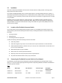
Copper:
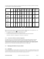
10Base-T
CAT3, 4 or 5
100m (328ft)
RJ45
10/20Mbps
100Base-TX
CAT5 or 5E
100m (328ft)
RJ45
100/200Mbps
Note: Since all switch ports are auto-sensing for both 10 and 100Mbps, it is recommended that high quality CAT5
cables or above (which work for both 10Mbps and 100Mbps) be used whenever possible in order to provide flexibility
in a mixed-speed network. Because the switch supports auto MDI/MDI-X detection, normal straight through cables
for both workstation connection and hub or switch connection can be used.
3.21
Connecting Copper Cables
The following procedure describes how to connect the 10/100Base-TX twisted pair segment to the RJ45 port. The
procedure is the same for both unshielded and shielded twisted pair cables.
1.
Using standard twisted pair media, insert either end of the cable with a RJ45 plug into the RJ45 connector of the
port. Note that, even though the connector is shielded, either unshielded or shielded cables and wiring may be
used.
2.
Connect the other end of the cable to the corresponding device.
3.
Use the LINK LED to ensure proper connectivity by noting that the LED will be illuminated when the unit is
powered and proper connection is established. If this does not help, ensure that the cable is connected properly
and that the device on the other end is powered and is not defective.
4.
For Port # 1 or 1SW, if the LINK LED is not illuminated, move the position of the switch which has a cross-over or
uplink for linking to another hub or switch.
3.22
Connecting Fiber ST Connectors
Use the following procedure for installations using ST (twist-lock) fiber connectors. This procedure applies to ports
using multimode ST fiber connectors.
1.
Before connecting the fiber optic cable, remove the protective dust caps from the tips of the fiber connectors.
Save these dust caps for future use.
2.
Wipe the ends of the dual connectors clean with a soft cloth or lint-free lens tissue dampened in alcohol. Make
certain the connectors are clean before connecting.
Note: One strand of the duplex fiber optic cable is coded using color bands at regular intervals; you must use the
color-coded strand on the associated ports at each end of the fiber optic segment.
3.
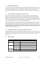
Connect the Transmit (TX) port (light colored post) on the CS fiber port to the Receive (RX) port of the remote
device. Begin with the color-coded strand of the cable for this first TX-to-RX connection.
4.
Connect the Receive (RX) port (dark colored post) to the Transmit (TX) port of the remote device. Use the noncolor coded fiber strand for this.
5.
The LINK LED on the front of the fiber connector will illuminate when a proper connection has been established
at both ends (and when power is ON). If LINK is not lit after cable connection, the normal cause is improper
cable polarity. Swap the fiber cables at the fiber connector to remedy this situation.
2
ProSwitch Converter Switch User’s Manual
Page 9